When you click on links to various merchants on this site and make a purchase, this can result in this site earning a commission. Affiliate programs and affiliations include, but are not limited to, the eBay Partner Network.
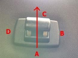
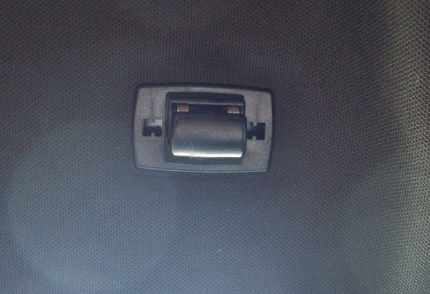
Wondering if anyone has had any luck pulling this piece down... It looks as if there is a trim/frame around the actual J-hook piece that holds the sun visor.
The arrow is pointing in the forward direction. And the letters are just in case you need some reference to describe where to pull/push/poke/squeeze...
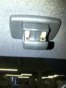
But if you prefer a picture without any distractions, then I've got one for you too (Hahaaa)
I've had my Radar detector for over a year now, and two tickets later ((1) forget to put it up and (2) was going on a short trip and didn't think I'd get tagged), I am yet to hard wire it. I've been wanting to tap into the visor clip as a power source since its right where I plan on mounting my Escort.
I've tried to pull down on that piece but obviously if there is any way to unclip it/not force it/not break it, that would be ideal.
Sorry for the delay, but here we go. Its actually pretty simple once you see the insides of it.
Disclaimer: As is always the case, you agree that you are doing this on your own, the events during which and the possible consequences including injuries to you and/or anyone else, and/or damages to your vehicle or any of its components are your own responsibility and no one else's, ..., blah blah, ... these steps are provided for entertainment purposes only...
Tools needed:
# A tool with a thin flat tip, a medium sized flat-head screwdriver would be ideal.
Step 1
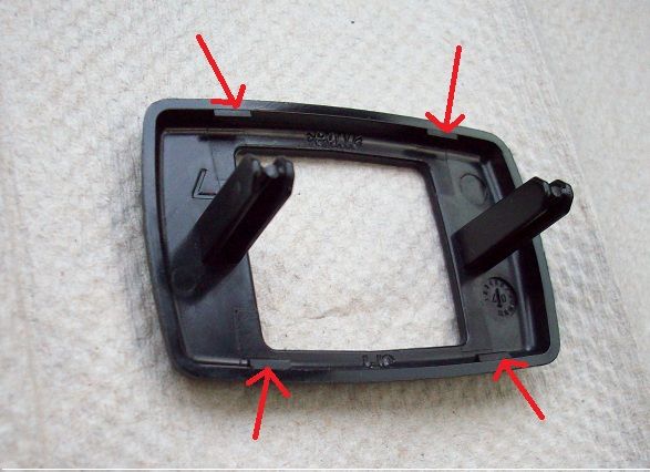
Insert the flat tip of the tool under the corner of the frame exactly as shown in the image below, and pull down on its handle until you hear a click.
Step 2
Repeat the same process for the remaining 3 corners while minding the location and direction of the tool.
The goal here is to unclip the frame off by snapping its 4 corners off at the locations indicated by the arrows.
The two rods that you see protruding upwards had so significance in the previous step but you will see in the next image how they play a role in holding the next part in its place.
Step 3
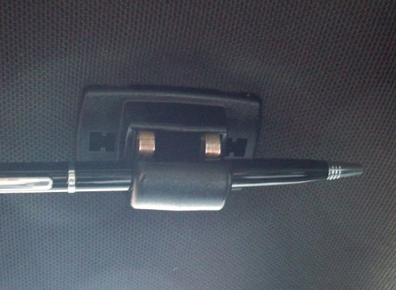
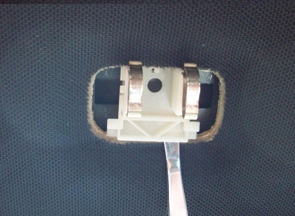
While it is clear that I am using a pen, this step is going to require more force than any pen can handle. (I only used the pen for illustration and instead, I used my thumbs but I could feel my right thumb was sore fort a few days later). You should use a screwdriver where you insert the shaft of the screwdriver onto the hook part of the clip and use that for leverage to pull down hard on the part to free it from the clip.
Ideally, if you can slightly push (slide the part) towards the front of the car and then pull down, it might get freed easily but either way, it will require some force to come off.
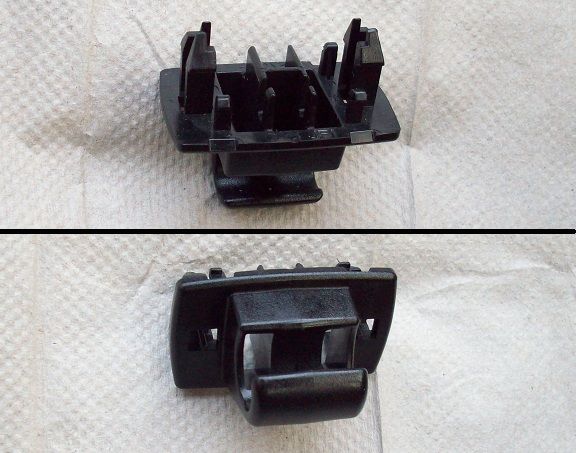
This is what it looks like above the part we can normally see.
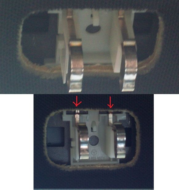
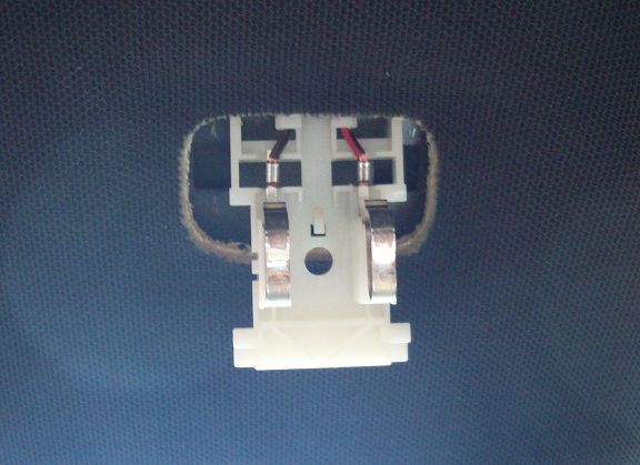
And this is what is left in that spot where the visor clip used to be:
The red arrows that you see are indicative of the direction where the two electric wires coming into the contacts come from. Whatever you do, don't pull down on that end.
Depending on what it is you are trying to do, you maybe able to finalize some sort of connection with this part as it is here; otherwise, go to the next step.
Step 4
You can see that there is some room for back and forth play on this part. But as previously cautioned, nothing can be gained by sliding it forward instead at this point in time, and if you need to get it out from under the headliner, then slide it back as far as it will go, and then use the same flat-head pry tool you used earlier to slip underneath this part, and leverage it out from front downward and out.
Once you've done that you can now slightly slide in forward to expose the rest of it an a bit more of the wires coming into it. Only slide it forward a little at a time until you can feel some resistance. This is as far as mine will come out:
For reassembly, and once you are done wiring and testing your connection, reverse the steps you followed to get to this point.
Important Note: Depending on what it is you are connecting to these terminals, you should keep in mind that while power is not continuous to this connection, it does in fact stay on for several minutes of you turning the ignition off and removing the key. This, and a weak battery may leave you without enough current to crank to a start.
While these instructions for removing the mirror visor clip are very helpful the wiring method described above is incorrect if you are going to tap power for your dash cam, radar detector, etc. from the mirror visor clip.
The negative (-) terminal on the mirror visor is not a proper ground. I encountered problems powering my radar detector wiring it this way. One clue that I did not have proper ground was that I would lose power to the radar detector when I switched on the visor mirror light.
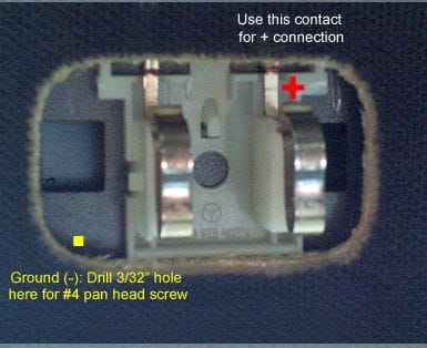
You can use the right terminal on the mirror visor clip to tap a positive (+) line for your dash cam or radar detector, but you will need to use the car body for your negative (-) (ground) connection as shown in the photo below.
To get a good ground (-) connection, drill a 3/32" hole (for a #4 pan head sheet metal screw) where the yellow square is in the photo. Then use a small cylindrical grinding wheel on a Dremel to grind off the paint around the hole so you will have a good bare-metal electrical contact. I soldered my ground wire to a small solder tab and then attached it to the body with a 1/4" long #4 pan head sheet metal screw in the 3/32" hole.
I encountered problems powering my radar detector wiring it this way.
I have had my radar detector connected to the +ve & -ve visor light terminal for over 2 years now and have not ever experienced any power loss to either the radar detector or the visor lights...
Originally Posted by Antique-Ace
The negative (-) terminal on the mirror visor is not a proper ground.
By definition, "Ground" can carry on different meanings and represent different settings depending on context and circuit elements. But that is not the issue here... The way I see it, the real issue is whether the negative terminal of the visor light is allowing sufficient current to run through the circuit to not only power the device that this circuit was designed for (that being a simple incandescent light bulb), but to also power up a radar detector that often contains a signal transmitter as well as a several signal receivers.
To further clarify this, I should simply use the same explanation that Mercedes Benz used to clarify the melting tail light connector for which MB issued a recall. In that explanation, MB offered that the type of material used for the ground connector was not allowing sufficient current through the circuit and as a result it would: (1) cause the tail light bulbs to be dimmed down (so much so that it even triggers a "light bulb out" warning on the dash), and (2) cause the actual connector to overheat and eventually show some sign of melting.
But this does not mean that the negative terminal of the tail light circuit isn't connected to the "chassis ground", and similarly, just because your radar detector is possibly drawing more current that this visor negative terminal would allow, does not mean that "the negative visor terminal is not proper ground"....
If for whatever reason this alternative circuit worked better for your amount of current draw, then I am glad you were able to figure it out, and we all appreciate the addendum.
I have had my radar detector connected to the +ve & -ve visor light terminal for over 2 years now and have not ever experienced any power loss to either the radar detector or the visor lights...
By definition, "Ground" can carry on different meanings and represent different settings depending on context and circuit elements. But that is not the issue here... The way I see it, the real issue is whether the negative terminal of the visor light is allowing sufficient current to run through the circuit to not only power the device that this circuit was designed for (that being a simple incandescent light bulb), but to also power up a radar detector that often contains a signal transmitter as well as a several signal receivers.
To further clarify this, I should simply use the same explanation that Mercedes Benz used to clarify the melting tail light connector for which MB issued a recall. In that explanation, MB offered that the type of material used for the ground connector was not allowing sufficient current through the circuit and as a result it would: (1) cause the tail light bulbs to be dimmed down (so much so that it even triggers a "light bulb out" warning on the dash), and (2) cause the actual connector to overheat and eventually show some sign of melting.
But this does not mean that the negative terminal of the tail light circuit isn't connected to the "chassis ground", and similarly, just because your radar detector is possibly drawing more current that this visor negative terminal would allow, does not mean that "the negative visor terminal is not proper ground"....
Sorry, I should have said, the negative visor terminal is not a proper chassis ground.
Nevertheless, I was experiencing problems running my Beltronics model Pro 600 radar detector (RD) wired to the +ve & -ve visor light terminals (see diagram below).
As I stated, the first problem I noted was a loss of power to the radar detector when I closed the switch (turned on) the visor mirror light. Looking at this wiring diagram, it is easy to see why this happens. (I am at a loss to explain why this does not occur with your radar detector if you have it wired like this)?
The next problem I experienced is that my RD would display a "low voltage" alert (that occurs when the voltage supply to the RD drops to 10.0 volts or less) at times when I had the display set to maximum brightness, especially when the RD was receiving a threat signal and sounding/displaying and alert message. I also noticed that the visor light bulb was actually glowing slightly when this occurred. This comes as no surprise considering the radar detector draws increased current when the display is set to maximum brightness, and draws even current more when it is sounding/displaying an alert (as indicated in the table below).
The visor light starts to glow because the radar detector is drawing voltage and current in series with a 3.5 ohm load (the visor light bulb).
I thought it was a good idea to alert readers of this thread that if their radar detector (or other load like a dash cam) draws enough current, they could experience similar problems to what I did. Using a chassis ground like I described avoids this potential (and in my case actual) problem with using +ve & -ve visor light terminals to power a load.
Last edited by Antique-Ace; 06-28-2015 at 04:04 PM.
Reason: Added table
Sorry, I should have said, the negative visor terminal is not a proper chassis ground.
OK...
And yet, I just used a continuity tester to check for a connection between the visor negative terminal in question and the "ground" you're suggesting resolved your problem.
Result: At least on my car, it showed that there is a connection between both points!
Moreover...
Originally Posted by Antique-Ace
(see diagram below).
^^This is YOUR diagram.. And it is not a true representation of the circuit you are attempting to draw.
For one, the voltage across the Radar detector terminal is ON at all times (as long as the ignition is on)... Whereas with the visor bulb, it is only ON when the switch is closed (i.e. the visor is drawn down and a connection is made between the contacts of the visor bar and the two terminals on the visor clip)!
In your drawing, and not only are BOTH, the Radar Detector AND the Visor Bulb on ALL the time (as long as the ignition key is on), but in addition, all the switch that you drew in there does is to short the Radar Detector terminals!
Here is how I would draw that circuit:
Furthermore, how do you figure that the visor bulb (a 5W5 bulb) is rated at 3.5 ohms?
In fact, at 3.5 ohms, and running a 12 volt potential through that bulb THIS Calculator is showing a power output of 41 watts! And yet those bulbs are rated at a nominal 5 Watts!
Needless to say, and as I stated above, my Escort 9500ix has worked like a charm for over 2 years. That said, the readers of this thread are free to use whichever method they see is appropriate for their needs. And thanks again for your input!
And yet, I just used a continuity tester to check for a connection between the visor negative terminal in question and the "ground" you're suggesting resolved your problem.
Result: At least on my car, it showed that there is a connection between both points!
Moreover...
^^This is YOUR diagram.. And it is not a true representation of the circuit you are attempting to draw.
For one, the voltage across the Radar detector terminal is ON at all times (as long as the ignition is on)... Whereas with the visor bulb, it is only ON when the switch is closed (i.e. the visor is drawn down and a connection is made between the contacts of the visor bar and the two terminals on the visor clip)!
In your drawing, and not only are BOTH, the Radar Detector AND the Visor Bulb on ALL the time (as long as the ignition key is on), but in addition, all the switch that you drew in there does is to short the Radar Detector terminals!
Here is how I would draw that circuit:
Furthermore, how do you figure that the visor bulb (a 5W5 bulb) is rated at 3.5 ohms?
In fact, at 3.5 ohms, and running a 12 volt potential through that bulb THIS Calculator is showing a power output of 41 watts! And yet those bulbs are rated at a nominal 5 Watts!
Needless to say, and as I stated above, my Escort 9500ix has worked like a charm for over 2 years. That said, the readers of this thread are free to use whichever method they see is appropriate for their needs. And thanks again for your input!
MY wiring diagram is a correct representation for my '13 C350 coupe and explains why I lost power to my radar detector every time I turned on the visor mirror light. Perhaps your need to consider that your MB may be wired differently?
The problems I experienced and previously described when my RD was wired using +ve & -ve visor light terminals are FACTS, and are fully accounted for by my wiring diagram. The FACT that I am no longer experiencing ANY of these problems using a chassis ground further validates my assertions.
I measured the filament resistance of a spare visor light bulb I had using my Fluke 179 Digital Multimeter. Perhaps I read the meter incorrectly? I will check it again when I have a chance, but the resistance of the visor light bulb is really not the significant issue here.
Thank you again for your excellent DIY of how to remove the visor clip. Once again, my goal was to alert readers of this thread of possible problems in using the +ve & -ve visor light terminals to power an electronic device and provide them with an alterative of using a chassis ground.
EDIT: I checked it again and the filament resistance of the visor mirror 194 type bulb measures 51.9 ohms.
Last edited by Antique-Ace; 06-30-2015 at 11:05 PM.
 07-11-2012, 05:53 PM