DIY C300 LED DRLs with Relay Diagram
 01-08-2014, 11:25 AM
#1
Junior Member
Thread Starter

Join Date: Nov 2012
Posts: 71
Likes: 0
Received 0 Likes
on
0 Posts
2008 Mercedes C300 4Matic Sport Sedan
DIY C300 LED DRLs with Relay Diagram
Allow me to start by saying that I wanted to start this thread more as a way to share electrical knowledge on the forums, and provide a reference for a different look than I’ve seen anywhere else. I was confident at the onset that when I finished this mod, it would not appear to be a rip off of a BMW, because of *how* I did the mod.
I have wanted LED DRLs since I got my 08 C300. It seemed that plenty of people had replaced their fog lights with newer style LEDs, but I actually use my fog lights in inclement weather like fog or snow, and didn’t want to sacrifice my safety at night for a look in the daytime. My factory xenons function as DRLs in the day via the system settings on the steering wheel, but I wanted a more updated look for it.
Next, I wanted it to look borderline OEM. I've had Hondas (and have used the avatar ever since) when I was a teenager, but I have higher standards for my Benz than just getting any old aftermarket solution and slapping it on. It had to stay distinctly Euro, and I really want to do things no one else has done (at least not that I’ve ever seen).
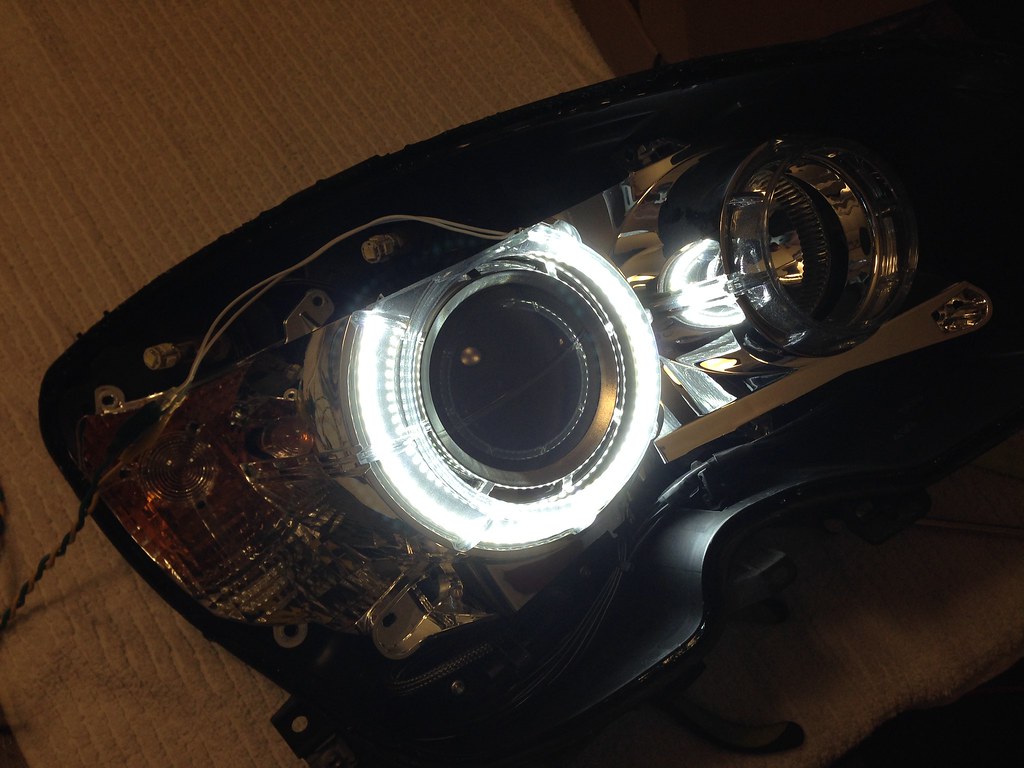
Here’s what I did. The Retrofit Source put their LED Halo DRLs on clearance for a retrofit replacement for the E46 BMW (I think that’s a 3-series). I had been looking at their straight light rods to install at the time, but these seemed like something worth taking a little chance on. . . If they fit well. I saw that they didn’t need a resistor or igniter to function, simplifying my wiring process too. I ordered them, and when they got here, I immediately powered them up to see what they looked like and how bright they were. If color or brightness wasn't good for the DRLs I would have scrapped them.
Here’s how they looked when hooked up directly to 14v:
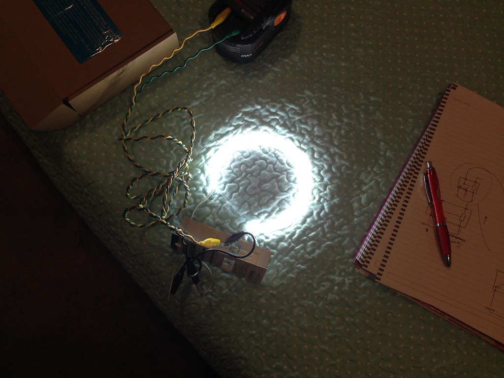
I had to use a dimmer and my multimeter to get the correct voltage/amperage for the dim mode that I wanted when the turn signal or park lights was on. When I settled on a non-distracting brightness I got the resistors that most closely matched the readings on the multimeter. The lights originally drew 4 mA at 14v, and the “dim mode” looked best at about 9-10v pulling 1.3mA. They have handy online calculators for resistors, and I used this one:
http://www.ngineering.com/led_calculators.htm
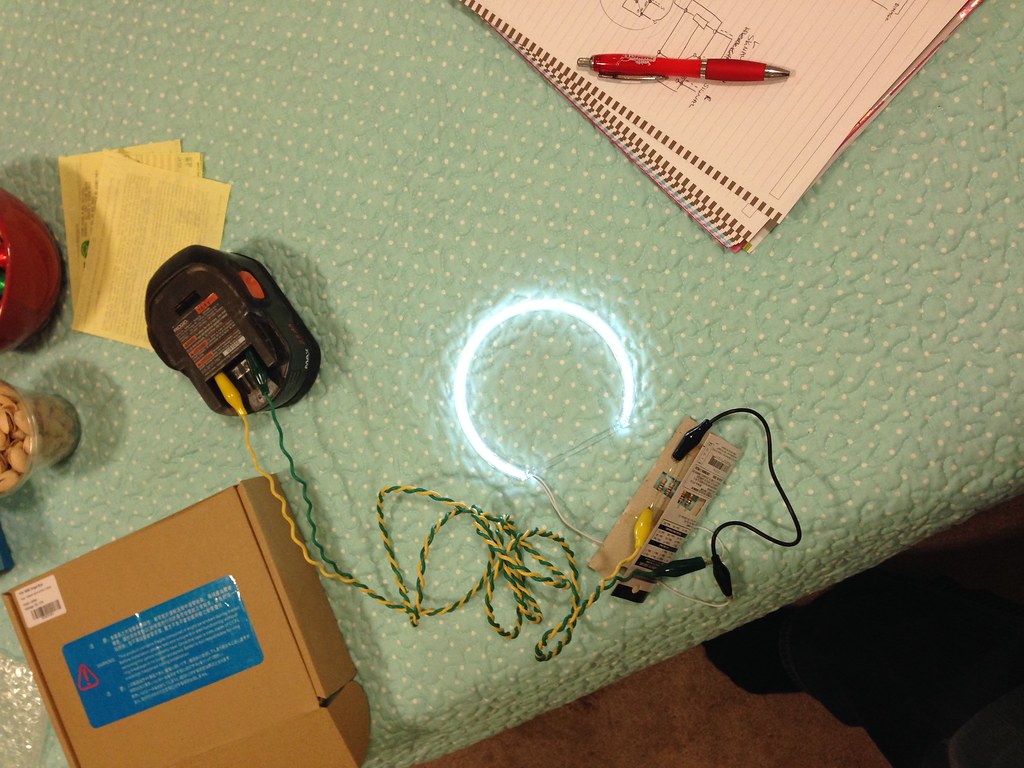
This is what the dimmed LED looked like.
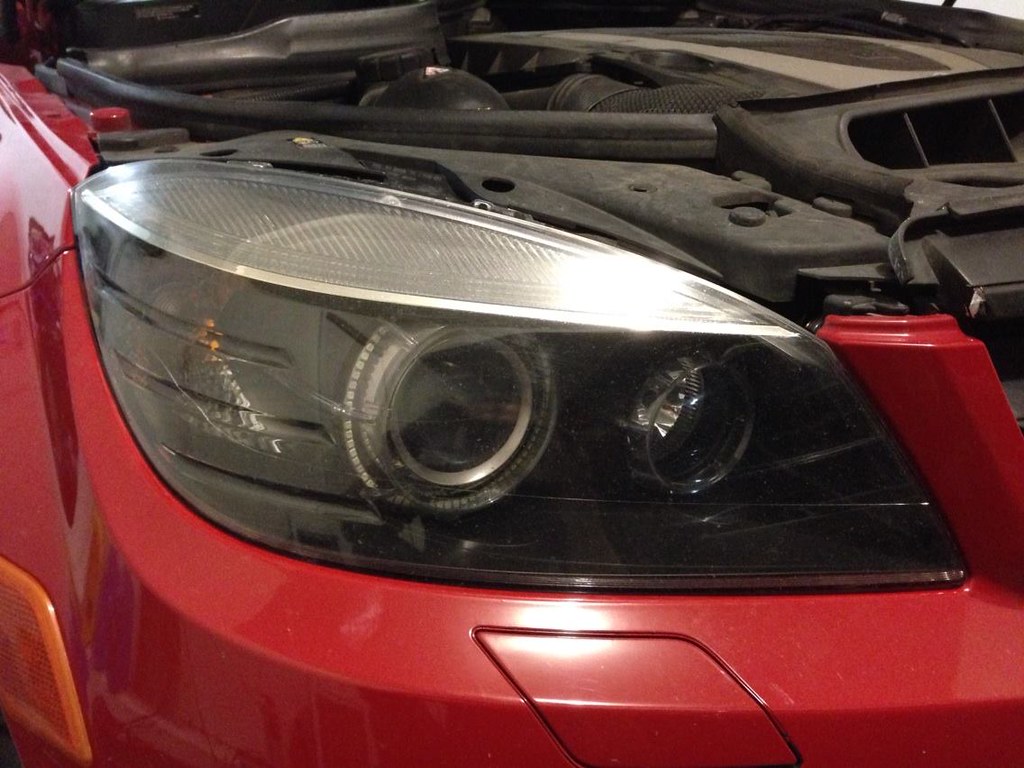
Next I took the headlights out of the car.

Again, I didn’t reinvent the wheel and I used this video from YouTube to make sure there weren’t any surprises waiting for me. The only difference in my headlights is that I had to disconnect and remove the headlight sprayers from the bottom of the housings.
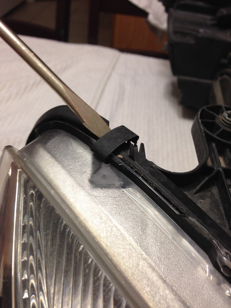
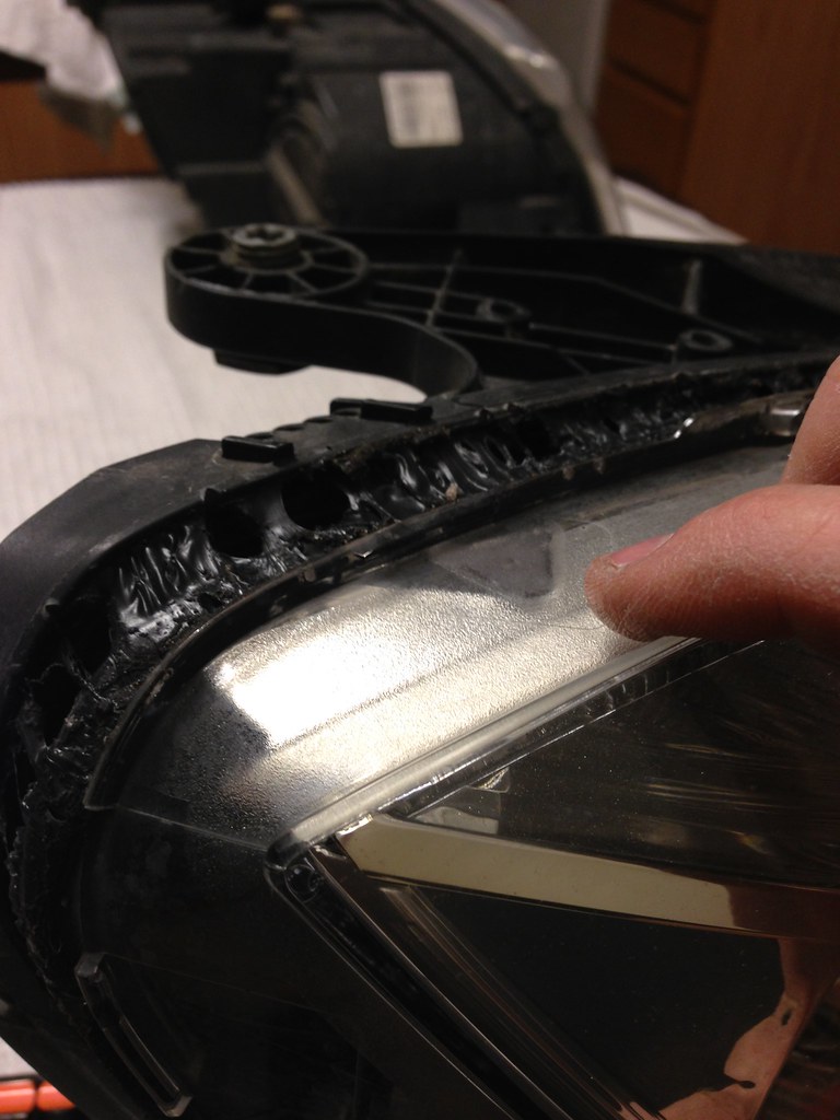
I use a heat gun to disassemble my lights instead of an oven, because I get better control over the heat, it’s faster, and I can still handle the light with my bare hands. There are four clips around each light that I popped off with a flat head screwdriver, and then it’s just heating up the bead of adhesive sealant around the light.
Clips:
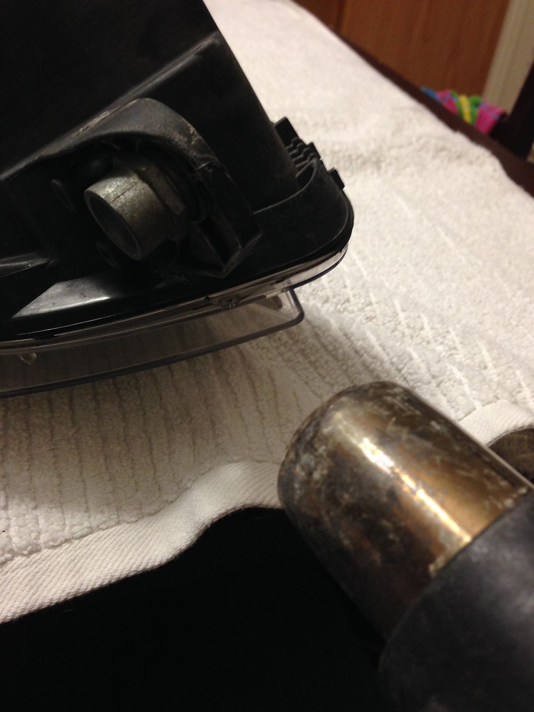
Disassembly:

Get the corners really well.
Start peeling them apart slowly:
When you get to this point, use the heat gun to separate all of these webs, and they'll neatly tuck to each side.
Viola!
And take off the chrome reflectors by removing all of the torx screws around it. All of them are visible.
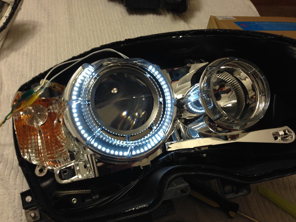
I now took the little clear plastic housing off the LED circuit board (for size and flexibility) and fit it on the inside of the clear plastic at the front of our projector shrouds. I thought it would look really cool shining from behind that. I think I thought right. There are 3 plastic tabs on the back side of the shroud that hold the clear plastic in place. I’m a fan of the black housings that C63s have, so I decided to paint the housings black on non-reflective surfaces. While I was taking all the plastic out to put in the LEDs, I painted the headlight housings black since it was all apart anyway.
In the middle you can see the clear shroud with the LEDs inside.

Here’s me test fitting the LEDs before painting the housing.
In "dim" mode:
And an up close view of my car's new palladium arc reactor a la Iron Man
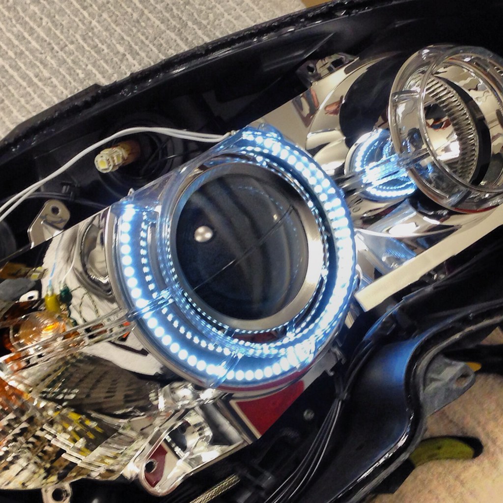
Luckily, the LEDs fit pretty snugly in the plastic housing, but I did accidentally pull the wires too far when installing them and had to redo the placement as I tugged it out of place on accident.
Notice how the right side is dimmer in the pic? It's because it's pulled back inside a little bit. Oops.
All in.
I drilled a small hole in the back of one of the eyelid caps and then used black RTV silicone to seal the hole up once the wire was through.
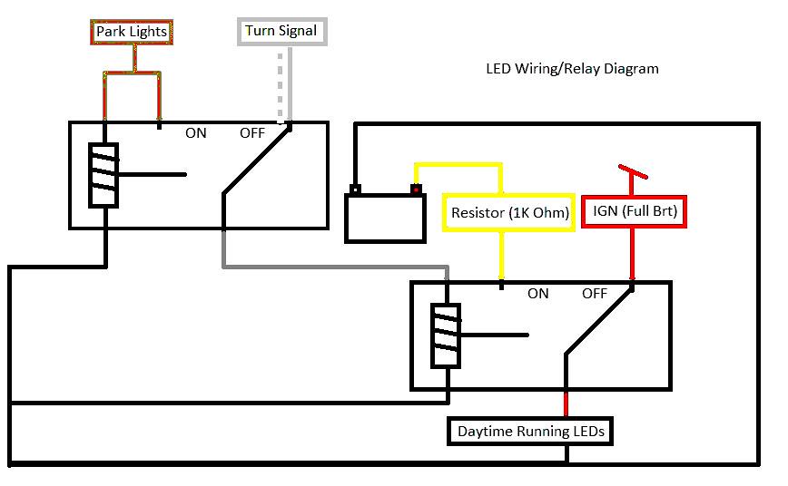
Almost as a completely separate project, I next tackled the wiring job. This took 2-5 pin relays on each side. If you haven’t used relays before, they make it possible to pull a trigger from a light source and use a completely separate power source. By doing this, I shouldn’t have any warning lights for bulbs out as I won’t be changing the power levels by very much at all. I’m not amazing with relays, so this part took forever and I really hope it benefits someone else more than just me. The idea is the following: When I turn on a signal, that will send a pulsing power through the first relay and down to the second one, triggering the switch inside to flip over to the “dim” wire with the resistor attached. If the park lights are on, then that triggers the first relay, sending the constant signal from the park light to the second relay, which also dims the DRL. This allowed me to accomplish similar-to-stock function for the lights. I can also now turn off my xenons from the steering wheel control. I’m still looking deeper into tapping into the factory DRL light going into the ballast, but I’d have to add additional relays, as this likely loses signal when turning on the headlights altogether. This would mean I would have to add diodes into the line too. I’m trying to keep it simple, and although I like the idea of being able to turn them off from the steering wheel, I think it will make for a larger mess than I’m willing to tackle right now.
Relay diagram I made for this project to make it work how I wanted:
I tapped constant power using an “add a circuit” fuse jumper in the fuse box, and kept the relays closer to the headlights for less wiring running back and forth. Overall, I needed to tap 4 wires, and by doing it the way I did, I also have them turn on when I unlock the car. The 4 wires to tap are:
Power from the battery or constant power from the fuse box. This is where I hooked the resistor inline (from the under hood fuse box).
Accessory turn on wire, which can be found in the fuse box too (actually I pulled from an engine control fuse).
Turn signal wire (one on each side)
Park light wire from the side marker light, because it's much easier to reach and tap into.
Ground is connected at the factory grounding location on each side of the car.
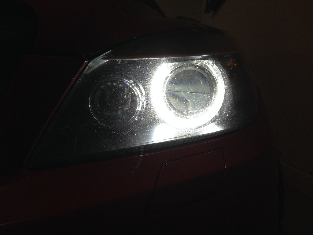
Here’s what it all looked like once it was wired up. (video to show the switching action)
I have wanted LED DRLs since I got my 08 C300. It seemed that plenty of people had replaced their fog lights with newer style LEDs, but I actually use my fog lights in inclement weather like fog or snow, and didn’t want to sacrifice my safety at night for a look in the daytime. My factory xenons function as DRLs in the day via the system settings on the steering wheel, but I wanted a more updated look for it.
Next, I wanted it to look borderline OEM. I've had Hondas (and have used the avatar ever since) when I was a teenager, but I have higher standards for my Benz than just getting any old aftermarket solution and slapping it on. It had to stay distinctly Euro, and I really want to do things no one else has done (at least not that I’ve ever seen).
Here’s what I did. The Retrofit Source put their LED Halo DRLs on clearance for a retrofit replacement for the E46 BMW (I think that’s a 3-series). I had been looking at their straight light rods to install at the time, but these seemed like something worth taking a little chance on. . . If they fit well. I saw that they didn’t need a resistor or igniter to function, simplifying my wiring process too. I ordered them, and when they got here, I immediately powered them up to see what they looked like and how bright they were. If color or brightness wasn't good for the DRLs I would have scrapped them.
Here’s how they looked when hooked up directly to 14v:
I had to use a dimmer and my multimeter to get the correct voltage/amperage for the dim mode that I wanted when the turn signal or park lights was on. When I settled on a non-distracting brightness I got the resistors that most closely matched the readings on the multimeter. The lights originally drew 4 mA at 14v, and the “dim mode” looked best at about 9-10v pulling 1.3mA. They have handy online calculators for resistors, and I used this one:
http://www.ngineering.com/led_calculators.htm
This is what the dimmed LED looked like.
Next I took the headlights out of the car.
Again, I didn’t reinvent the wheel and I used this video from YouTube to make sure there weren’t any surprises waiting for me. The only difference in my headlights is that I had to disconnect and remove the headlight sprayers from the bottom of the housings.
I use a heat gun to disassemble my lights instead of an oven, because I get better control over the heat, it’s faster, and I can still handle the light with my bare hands. There are four clips around each light that I popped off with a flat head screwdriver, and then it’s just heating up the bead of adhesive sealant around the light.
Clips:
Disassembly:
Get the corners really well.
Start peeling them apart slowly:
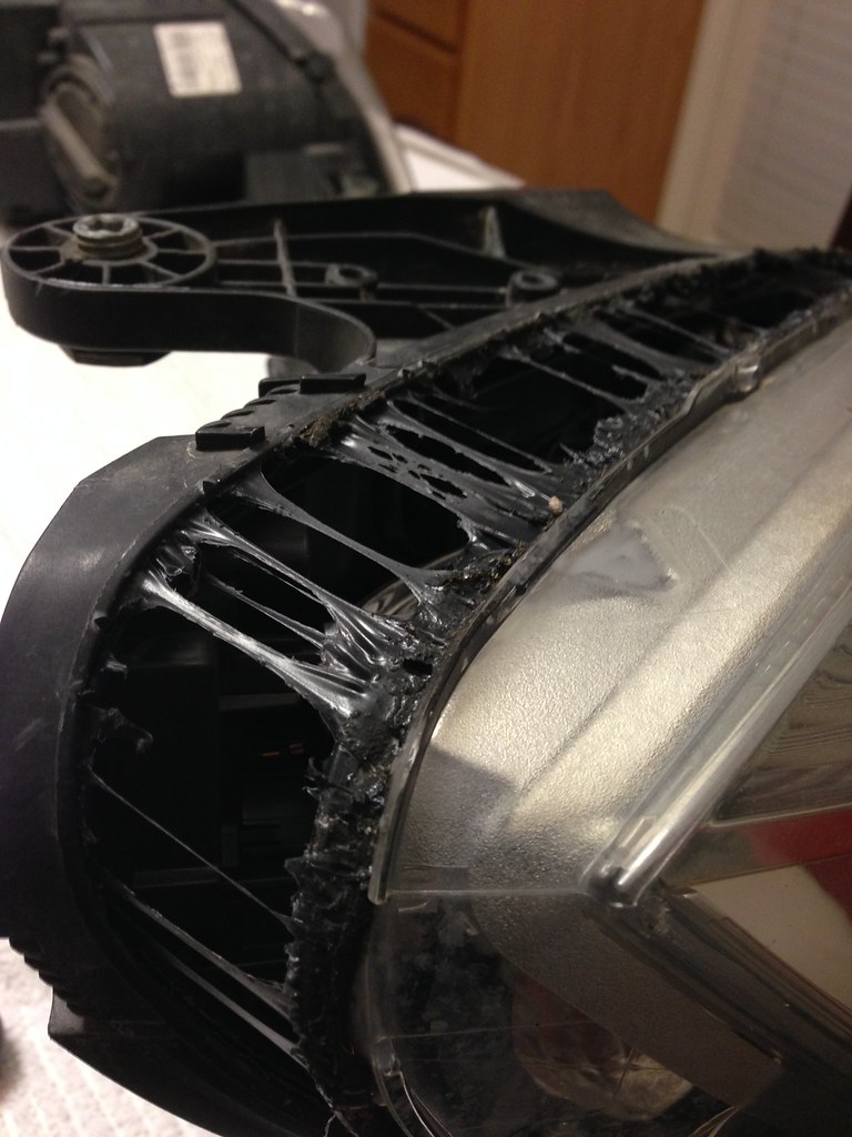
When you get to this point, use the heat gun to separate all of these webs, and they'll neatly tuck to each side.
Viola!
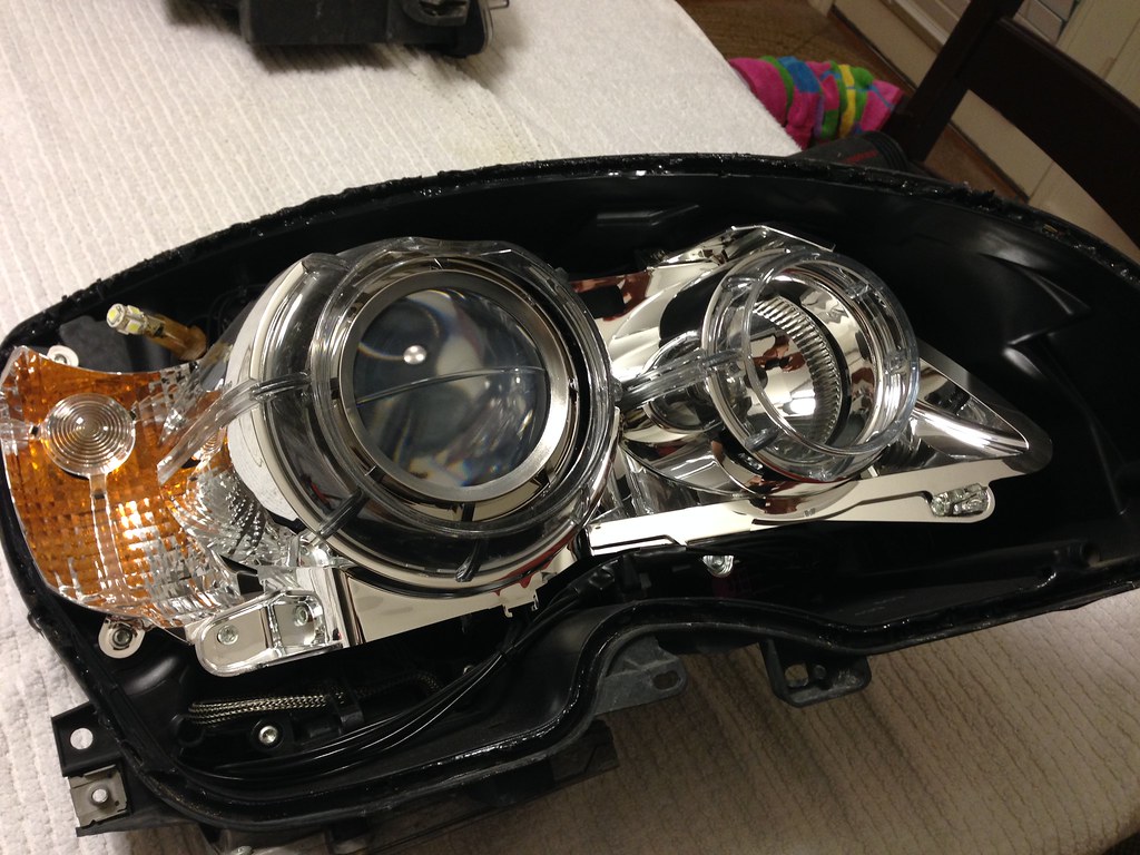
And take off the chrome reflectors by removing all of the torx screws around it. All of them are visible.
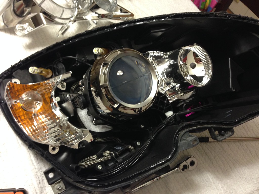
I now took the little clear plastic housing off the LED circuit board (for size and flexibility) and fit it on the inside of the clear plastic at the front of our projector shrouds. I thought it would look really cool shining from behind that. I think I thought right. There are 3 plastic tabs on the back side of the shroud that hold the clear plastic in place. I’m a fan of the black housings that C63s have, so I decided to paint the housings black on non-reflective surfaces. While I was taking all the plastic out to put in the LEDs, I painted the headlight housings black since it was all apart anyway.
In the middle you can see the clear shroud with the LEDs inside.
Here’s me test fitting the LEDs before painting the housing.
In "dim" mode:
And an up close view of my car's new palladium arc reactor a la Iron Man
Luckily, the LEDs fit pretty snugly in the plastic housing, but I did accidentally pull the wires too far when installing them and had to redo the placement as I tugged it out of place on accident.
Notice how the right side is dimmer in the pic? It's because it's pulled back inside a little bit. Oops.
All in.
I drilled a small hole in the back of one of the eyelid caps and then used black RTV silicone to seal the hole up once the wire was through.
Almost as a completely separate project, I next tackled the wiring job. This took 2-5 pin relays on each side. If you haven’t used relays before, they make it possible to pull a trigger from a light source and use a completely separate power source. By doing this, I shouldn’t have any warning lights for bulbs out as I won’t be changing the power levels by very much at all. I’m not amazing with relays, so this part took forever and I really hope it benefits someone else more than just me. The idea is the following: When I turn on a signal, that will send a pulsing power through the first relay and down to the second one, triggering the switch inside to flip over to the “dim” wire with the resistor attached. If the park lights are on, then that triggers the first relay, sending the constant signal from the park light to the second relay, which also dims the DRL. This allowed me to accomplish similar-to-stock function for the lights. I can also now turn off my xenons from the steering wheel control. I’m still looking deeper into tapping into the factory DRL light going into the ballast, but I’d have to add additional relays, as this likely loses signal when turning on the headlights altogether. This would mean I would have to add diodes into the line too. I’m trying to keep it simple, and although I like the idea of being able to turn them off from the steering wheel, I think it will make for a larger mess than I’m willing to tackle right now.
Relay diagram I made for this project to make it work how I wanted:
I tapped constant power using an “add a circuit” fuse jumper in the fuse box, and kept the relays closer to the headlights for less wiring running back and forth. Overall, I needed to tap 4 wires, and by doing it the way I did, I also have them turn on when I unlock the car. The 4 wires to tap are:
Power from the battery or constant power from the fuse box. This is where I hooked the resistor inline (from the under hood fuse box).
Accessory turn on wire, which can be found in the fuse box too (actually I pulled from an engine control fuse).
Turn signal wire (one on each side)
Park light wire from the side marker light, because it's much easier to reach and tap into.
Ground is connected at the factory grounding location on each side of the car.
Here’s what it all looked like once it was wired up. (video to show the switching action)
Last edited by hondafan; 01-08-2014 at 11:46 AM.
 01-26-2014, 11:23 PM
#4
Senior Member
Join Date: Aug 2010
Location: So Cal
Posts: 277
Likes: 0
Received 0 Likes
on
0 Posts
W204
Wow, that is a really nice job!
I'm thinking about doing some modifications to my head lights too, but I have a question. The shop that did repairs for a frontal collision I had did not align the housing right.
So the headlight spacing is a little bit off. The gaps between the fender and the bumper seems to be really tight. Would this possibly cause any issues if I were to go ahead with the removal of the housings?


