When you click on links to various merchants on this site and make a purchase, this can result in this site earning a commission. Affiliate programs and affiliations include, but are not limited to, the eBay Partner Network.
Does anyone have a diagram of the Aux Air Pump lines and what ports they should go in? I have a 1999 Vert that had a bad air pump. I replaced the pump and now can lock and unlock the gas door and trunk. The door locks move up and down, but still no locking there (haven't dug into that yet...). When I put the lines back on the new pump from where they were in the old pump, there was no movement from anything vacuum controlled. I put the lines in the location that it appeared the vehicle that used to have this air pump. This is how I got some items working. There was one port that was "leaking" vacuum that I put an old connector in with a vacuum cap. Any assistance would be great!!
I did find my vacuum leak for my AC...the main actuator for the modes has a bad leak...new one on order from my local MB dealership. Its nice having one right around the corner from me...and that I get a huge break on pricing, thanks to working in the Parts Department of a Buick GMC dealership.
I'm glad to hear you're sorting out your problems!
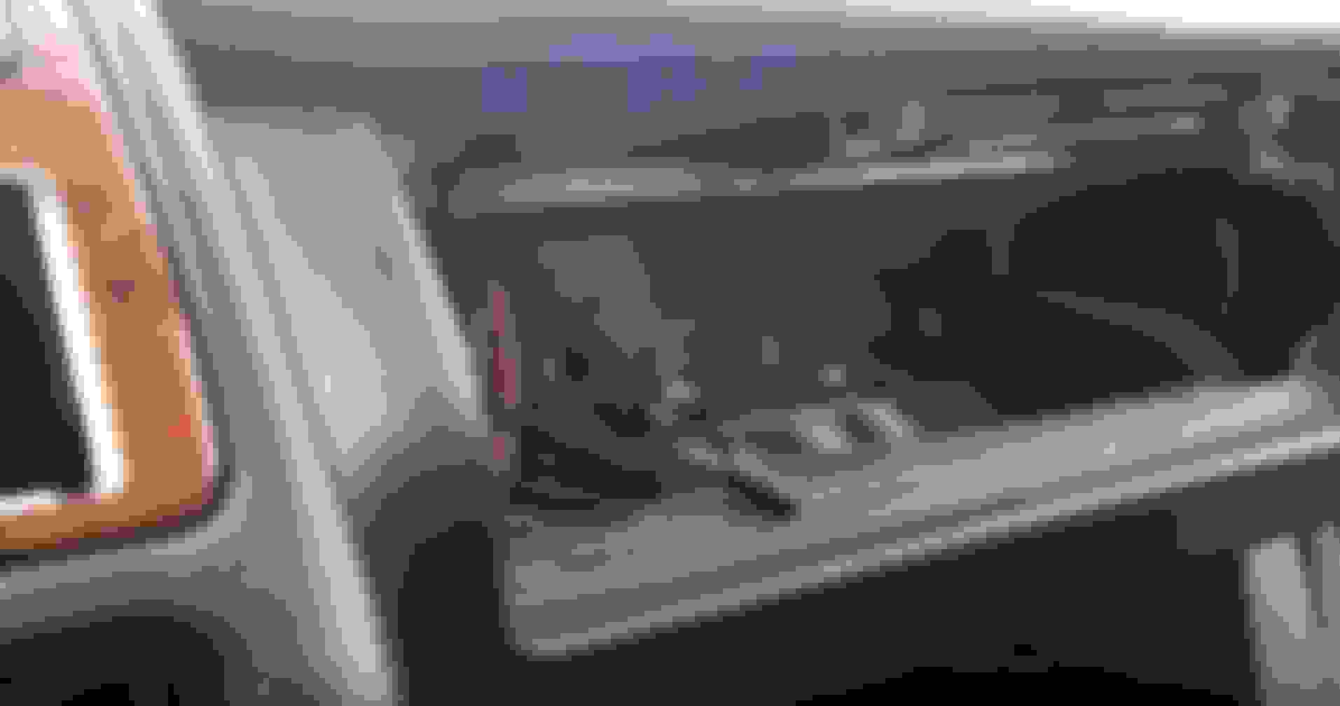
I think the vacuum lines travel through the passenger side of the car to the front, than separate once they reach the passenger side footwell. One goes into the door, another one goes left for the drivers side door and another one goes into the dash. There it enters the vacuum distributor which transforms it into 724 lines. This may be a problematic area. This bugger is held on by a metal bracket. On the top it just "slides in" in two places, while on the bottom it's held on to the blower motor housing by a single T20 (if I recall correctly) screw. If you do remove it and after reattachment it sags, you'll have to remove the glovebox to attach it properly. Here are some random pictures of it:
The bracket from the top with the glovebox removed.
The bracket from the bottom. You can just barely see a part of it in the right.
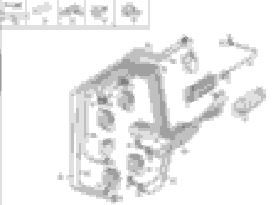
A diagram of AC vents vacuum lines coming out of the vacuum distributor bugger:
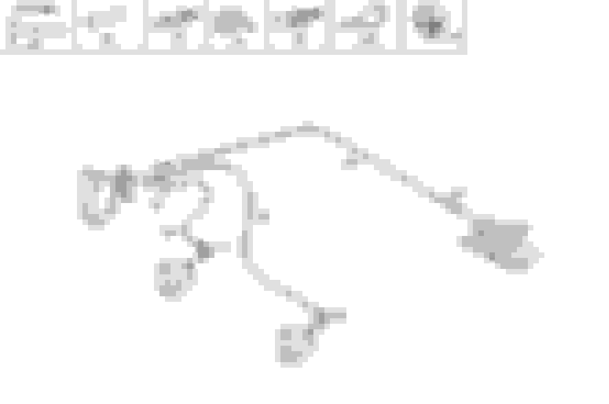
A diagram of rear headrests vacuum lines:
A diagram of the AC/Heat vacuum line (this would be The Master Flap, I guess):
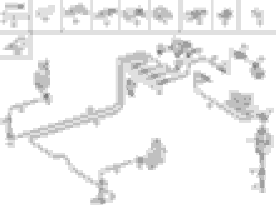
A diagram of the Central Locking vacuum lines:
Good luck and DO keep us posted on your progress :-)
Great information!! Thank you for posting!!!! Now to find a diagram of the Aux Vac Pump. I think the previous owner replaced the pump and messed up which lines go where on the pump.
 09-23-2016, 04:27 PM