DIY Front lower ball joints
 01-17-2014, 10:04 PM
#1
Super Member
Thread Starter

Join Date: Dec 2005
Location: Rochester, NY
Posts: 806
Likes: 0
Received 17 Likes
on
17 Posts
2009 S550 AMG sport pckg. 2014 Ford F-150 Lariat Supercrewcab
DIY Front lower ball joints
Hi Everyone,
If anyone is interested I'll be changing the front lower ball joints on my '07 ml350. I noticed the SUV drifts when driving on the expressway and I keep having to adjust. I did the prybar test and sure enough they are loose, but not too severe yet. I'll be getting the parts next week so stay tuned...
I'll posted tools and specs and pics
to be continued...
 01-22-2014, 11:44 PM
#3
Super Member
Thread Starter
Join Date: Dec 2005
Location: Rochester, NY
Posts: 806
Likes: 0
Received 17 Likes
on
17 Posts
2009 S550 AMG sport pckg. 2014 Ford F-150 Lariat Supercrewcab
Today the parts came in and I disassembled the passenger side. It was much easier than I thought it would be with the exception of the abs sensor and the snap ring. I ordered a pair of abs sensors from ebay for 50 bucks each which isnt too bad. I ended up getting the wrong bearing also and it looks like I may have to pay a visit to the dealer tomorrow. I got part # 510097 from timken and it ended up too big. There is a 98mm and a 90mm bearing it looks like but every parts store I've gone to lists 510097 as the part. The MB part # is A1649810406. As soon as I get the parts I will post pics and do a write up. The balljoints and the hub and bearing came right out with a little persuasion of the hammer  This was much easier than my e320
This was much easier than my e320
01-23-2014, 11:15 PM
#4
Super Member
Thread Starter
Join Date: Dec 2005
Location: Rochester, NY
Posts: 806
Likes: 0
Received 17 Likes
on
17 Posts
2009 S550 AMG sport pckg. 2014 Ford F-150 Lariat Supercrewcab
Hey everyone. I just got done changing the ball joints and bearings in my 07 ML350. I've done them on my 03 E320 before and overall I would say that the ML350 was easier but there are a few things to know and watch out for with the ML350. First and foremost make sure you have the right tools do this job. Air tools are not required but highly recommended. Here is a list of tools you MUST have before even attempting this:
17mm
21mm socket
22mm socket
36mm
13mm
t27 torx bit
t10 torx socket
extensions
2 jaw puller
1in socket
Ball joint separator
good pair of snap ring pliers
harbor freight tools bearing removal/installation set
torque wrench
breaker bar
spindle locking nut socket set from advanceauto
torch
assortment of screwdrivers
hammer
angle grinder or dremel tool.
work bench with vise
to make life easier these would also help but not absolutely necessary:
air tools
shop press
Parts:
Bearing: there was some confusion about the bearing. A1649810406 is the only part that fit and is available on ebay or at the dealer. I wouldn't bother with going to advanceauto parts. They and other parts stores have the part listed as 510097 which is too big.
Ball joint: I got a moog balljoint which has a limited lifetime warranty
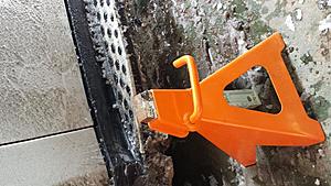
Ok so now begin with jacking up the car. The jackpoint is this black metal liftpoint behind the belly pan. I made my own modified jackstands by hacking off the ends to create a rectangular shape that will mate with the plastic lift points.
Next using a 17mm socket loosen the lug bolts. I used an air gun.

Next remove the brake caliper and collar nut on the drive axle. If you don't have airtools do the collar nut first and jam a screwdriver into the rotor to keep the axle still. If you have airtools order does not matter.
For the brakes I decided to take the entire caliper/bracket assembly off. Cut this ziptie to free the lines and harness. Using 22mm socket, loosen the bracket bolts. Remove assembly and suspend with a hanger or other device


Remove the collar nut using 36mm socket ( it's a ***** without airtools!!!)


Remove torx screw on rotor with t27 bit


Remove rotor
Use a 2 jawed puller to press the drive axle out of the hub. I would highly suggest not using a hammer so you don't run the risk of ruining the threads. This driveaxle is very expensive and very difficult to replace.

Loosen the upper ball joint nut using 21mm socket. Remove the nut completely then thread it back on just a few threads.
Loosen tie rod nut with 22mm socket. Remove completely and then thread it on a few threads.
Now here's the first Problem I ran into. You need to remove the abs sensor but mine were both frozen. I tried everything from heat to penetrating oil but no go and they broke so I cut them and ordered new ones on ebay for $50 a piece. I later ground down the plastic and drilled them out.


Using ball joint separator, separate the upper ball joint. It will drop a bit but the nut will catch it. unthread the nut and let it drop


Swing the steering knuckle out of the way enough to get the drive axle up and out of the way.

separate tie rod end then unthread nut


Now the steering knuckle is hanging by only the lower ball joint. When you loosen the nut it will pretty much just fall out and require no pressing out so be ready to hold the steering knuckle. Use the 1in socket to loosen the lower ball joint. If the joint spins with the nut, put the jack under the ball joint and add some weight on enough to stop the joint from spinning and the nut should come off. The 1inch is alittle too big for the nut but not enough to strip it and the reason why I used this is because there is a tight fit between the nut and the drive axle and it allowed the extension to wobble a bit.

Now your steering knuckle is out.

Remove the four brake dust pan screws with a 13mm six point socket

Next is time to hammer out the ball joint and hub. You don't need a balljoint press or shop press to get these out luckily, and it saves a lot of time. On my e320 this step took forever!!! But on the ML350 a few blows of the hammer knocked the ball joint right out.


After getting your old ball joint out next go to your harbpr freight or similar bearing extraction set and find a cup that just sits over the inner hub race and a suitable plate to cover it and strike like this:


time for the hammer again. Now your hub should fall out with the inner bearing race
Next comes the fun part. Getting the snap ring off. This is going to waste a lot of time. It is rusted and lodged into a groove and you have to get it out. There are two holes. What I did to get it loose was I used needle nose pliers and stuck them into each hole separately and pried around in every direction until I saw each side dislodge just a bit. Then try and pry on it again to create a small gap and put heat on it. The heat should slowly make each side open up slowly. you can also use a screw driver to pry on the groove (easier said than done!!!!) Now with the ring loosened use the snap ring pliers to remove the snap ring. A little tip is to take the snap ring and make a bevel around the edges with a grinding wheel and that way it will go right back into the groove afterwards.


Now find a plate that covers at least the inner race of the bearing. Place the plate in the back and whack away until the bearing comes out. Was a lot quicker that using press tools.


Next clean out the snap ring groove with a wire brush.
Next is time to install the ball joint. insert the ball joint into the bore and thread nut on. This is when airtools come in handy. I was able to find the special tool Mercedes uses at advanceauto. It is just a spindle locking nut socket. This is the kit you can rent and use and here is the socket.


Setup the steering knuckle in a vise and lube the ball joint then go to town tightening it. Make sure there is no gap between the ball joint flange and the steering knuckle. It will be a slow process so be patient. The ball joint is fine threaded so you are going to think it is going nowhere but it will slowly go on. The torque says 300nm on alldatadiy.com but
I just used the goodentite method. My air gun goes up to 500ftlbs so it was prolly tight enough.


Next lube the bearing to get it ready to go in. Now here's where you need to be VERY CAREFUL!!!!!!!!!!!!!!!!!!!!!!!!!!!!!!!!!!!!!!!!!!! !!! The bearing has to be installed in specific direction. One side has a dark ring that is magnetic and the other side has a shiny ring that is not. The magnetic end has to be facing the abs sensor and acts like a reluctor ring so make sure the dark ring faces into the carrier!!!!!! If you are not sure, I noticed if I put a screwdriver near the magnetic end I felt the magnetic force on the screwdriver whereas on the other side there was none
17mm
21mm socket
22mm socket
36mm
13mm
t27 torx bit
t10 torx socket
extensions
2 jaw puller
1in socket
Ball joint separator
good pair of snap ring pliers
harbor freight tools bearing removal/installation set
torque wrench
breaker bar
spindle locking nut socket set from advanceauto
torch
assortment of screwdrivers
hammer
angle grinder or dremel tool.
work bench with vise
to make life easier these would also help but not absolutely necessary:
air tools
shop press
Parts:
Bearing: there was some confusion about the bearing. A1649810406 is the only part that fit and is available on ebay or at the dealer. I wouldn't bother with going to advanceauto parts. They and other parts stores have the part listed as 510097 which is too big.
Ball joint: I got a moog balljoint which has a limited lifetime warranty
Ok so now begin with jacking up the car. The jackpoint is this black metal liftpoint behind the belly pan. I made my own modified jackstands by hacking off the ends to create a rectangular shape that will mate with the plastic lift points.

Next using a 17mm socket loosen the lug bolts. I used an air gun.
Next remove the brake caliper and collar nut on the drive axle. If you don't have airtools do the collar nut first and jam a screwdriver into the rotor to keep the axle still. If you have airtools order does not matter.
For the brakes I decided to take the entire caliper/bracket assembly off. Cut this ziptie to free the lines and harness. Using 22mm socket, loosen the bracket bolts. Remove assembly and suspend with a hanger or other device
Remove the collar nut using 36mm socket ( it's a ***** without airtools!!!)
Remove torx screw on rotor with t27 bit
Remove rotor
Use a 2 jawed puller to press the drive axle out of the hub. I would highly suggest not using a hammer so you don't run the risk of ruining the threads. This driveaxle is very expensive and very difficult to replace.
Loosen the upper ball joint nut using 21mm socket. Remove the nut completely then thread it back on just a few threads.
Loosen tie rod nut with 22mm socket. Remove completely and then thread it on a few threads.
Now here's the first Problem I ran into. You need to remove the abs sensor but mine were both frozen. I tried everything from heat to penetrating oil but no go and they broke so I cut them and ordered new ones on ebay for $50 a piece. I later ground down the plastic and drilled them out.
Using ball joint separator, separate the upper ball joint. It will drop a bit but the nut will catch it. unthread the nut and let it drop
Swing the steering knuckle out of the way enough to get the drive axle up and out of the way.
separate tie rod end then unthread nut
Now the steering knuckle is hanging by only the lower ball joint. When you loosen the nut it will pretty much just fall out and require no pressing out so be ready to hold the steering knuckle. Use the 1in socket to loosen the lower ball joint. If the joint spins with the nut, put the jack under the ball joint and add some weight on enough to stop the joint from spinning and the nut should come off. The 1inch is alittle too big for the nut but not enough to strip it and the reason why I used this is because there is a tight fit between the nut and the drive axle and it allowed the extension to wobble a bit.
Now your steering knuckle is out.
Remove the four brake dust pan screws with a 13mm six point socket
Next is time to hammer out the ball joint and hub. You don't need a balljoint press or shop press to get these out luckily, and it saves a lot of time. On my e320 this step took forever!!! But on the ML350 a few blows of the hammer knocked the ball joint right out.
After getting your old ball joint out next go to your harbpr freight or similar bearing extraction set and find a cup that just sits over the inner hub race and a suitable plate to cover it and strike like this:
time for the hammer again. Now your hub should fall out with the inner bearing race
Next comes the fun part. Getting the snap ring off. This is going to waste a lot of time. It is rusted and lodged into a groove and you have to get it out. There are two holes. What I did to get it loose was I used needle nose pliers and stuck them into each hole separately and pried around in every direction until I saw each side dislodge just a bit. Then try and pry on it again to create a small gap and put heat on it. The heat should slowly make each side open up slowly. you can also use a screw driver to pry on the groove (easier said than done!!!!) Now with the ring loosened use the snap ring pliers to remove the snap ring. A little tip is to take the snap ring and make a bevel around the edges with a grinding wheel and that way it will go right back into the groove afterwards.
Now find a plate that covers at least the inner race of the bearing. Place the plate in the back and whack away until the bearing comes out. Was a lot quicker that using press tools.
Next clean out the snap ring groove with a wire brush.
Next is time to install the ball joint. insert the ball joint into the bore and thread nut on. This is when airtools come in handy. I was able to find the special tool Mercedes uses at advanceauto. It is just a spindle locking nut socket. This is the kit you can rent and use and here is the socket.
Setup the steering knuckle in a vise and lube the ball joint then go to town tightening it. Make sure there is no gap between the ball joint flange and the steering knuckle. It will be a slow process so be patient. The ball joint is fine threaded so you are going to think it is going nowhere but it will slowly go on. The torque says 300nm on alldatadiy.com but
I just used the goodentite method. My air gun goes up to 500ftlbs so it was prolly tight enough.
Next lube the bearing to get it ready to go in. Now here's where you need to be VERY CAREFUL!!!!!!!!!!!!!!!!!!!!!!!!!!!!!!!!!!!!!!!!!!! !!! The bearing has to be installed in specific direction. One side has a dark ring that is magnetic and the other side has a shiny ring that is not. The magnetic end has to be facing the abs sensor and acts like a reluctor ring so make sure the dark ring faces into the carrier!!!!!! If you are not sure, I noticed if I put a screwdriver near the magnetic end I felt the magnetic force on the screwdriver whereas on the other side there was none
Last edited by Nickthegreek; 01-24-2014 at 10:32 PM.
01-24-2014, 10:33 PM
#5
Super Member
Thread Starter
Join Date: Dec 2005
Location: Rochester, NY
Posts: 806
Likes: 0
Received 17 Likes
on
17 Posts
2009 S550 AMG sport pckg. 2014 Ford F-150 Lariat Supercrewcab
So now that you have the correct orientation it is time to press the bearing in. This can be done with either the bearing kit from harbor freight which uses plates and a screw or a shop press. I did one side with the kit and the other with a shop press and found that the shop press was a PITA because everything has to be perfectly lined up whereas with the kit it stayed lined up. The shop press was quicker though once the bearing got seated. Your call which one you want to do


Make sure the bearing seats right up to the ridge by the ABS sensor.
Install snap ring back. If it does not quite fit try removing and stretching it out and tapping it with a screwdriver and hammer so it lodges into the groove.


Now using a dremel tool score a groove on the inner bearing race that is stuck on the hub. Go about halfway through the race and then set it up on a vice and take a cold chisel and hammer and hit it until the inner race cracks. after it cracks it should come right off. You might knick the hub alittle which is no big deal


After removing the inner race from the hub, its now time to press the hub back into the new bearing. lube the hub and use a plate that will cover the inner bearing race on the press side. This is the plate I used and it worked out perfectly.
I used the press on mine. Heres a little trick to make sure you don't overtighten the bearings. press the hub in and leave just a millimeter to go until it is fully on. I over-tightened bearings a while back with the press and they prematurely wore. When you tighen the collar nut later it will press the hub the rest of the way in and only whatever is specified by the factory and will have the right preload. Don't leave too much space though or the hub will be way out of alignment and the rotor will not fit. A millimeter is just enough.
Now it's time for installation.
Jack up from under the tie rod end
insert the steering knuckle into the tie rod and the lower ball joint holes. tighten each nut a few threads. You can now lower the jack. Now take the drive axle and insert it back into the hub.Part of the threaded will stick out. Take the collar nut and start threading it by hand to draw in the drive axle.
Jack up from under the lower ball joint and put some weight on the joint and tighten it with the 1in and the extension again. I just used the air gun but ill post the actual torque later ( good luck with a torque wrench it is pressed for space).
Lower the jack and jack up on the tie rod end just a bit to put some weight on it. Again I used the airgun 22mm.
Now jack up on the lower ball joint so the upper ball joint aligns. again airgun 21mm
Install Brake dust plate and bolts with 13mm sockets
Install Rotor. Align and tighten torx screw
Install brake caliper assembly back and tighten 22mm bolts with..... air gun
Now is when correct torque is critical. the torque for the collar nut is 250nm (185ftlbs) then go 45 degrees beyond. Because I left some extra space in the hub the rotor rubbed against the bracket until I tightened the collar nut. To tighten the collar nut, thread in a bolt into the hub and rotor. Jam a screw driver in between the brake bracket and rotor vane. Now tighten to the initial 185ftlbs then go 45 degrees beyond. Now the wheels spun freely.
reinstall the harness removed from the brakes and ziptie it back.
Reinstall wheels and torque.
Lower car
Take the car out for a ride and enjoy the ride and all the saved money!!!!
I'll be getting the new abs sensors Friday so in the meantime I wont have ABS and traction but it still drives fine in the snow. I'll keep you posted on installing the abs sensor. I will edit this and put the pics in also. Uploading them to flickr now
Make sure the bearing seats right up to the ridge by the ABS sensor.
Install snap ring back. If it does not quite fit try removing and stretching it out and tapping it with a screwdriver and hammer so it lodges into the groove.
Now using a dremel tool score a groove on the inner bearing race that is stuck on the hub. Go about halfway through the race and then set it up on a vice and take a cold chisel and hammer and hit it until the inner race cracks. after it cracks it should come right off. You might knick the hub alittle which is no big deal
After removing the inner race from the hub, its now time to press the hub back into the new bearing. lube the hub and use a plate that will cover the inner bearing race on the press side. This is the plate I used and it worked out perfectly.
I used the press on mine. Heres a little trick to make sure you don't overtighten the bearings. press the hub in and leave just a millimeter to go until it is fully on. I over-tightened bearings a while back with the press and they prematurely wore. When you tighen the collar nut later it will press the hub the rest of the way in and only whatever is specified by the factory and will have the right preload. Don't leave too much space though or the hub will be way out of alignment and the rotor will not fit. A millimeter is just enough.
Now it's time for installation.
Jack up from under the tie rod end
insert the steering knuckle into the tie rod and the lower ball joint holes. tighten each nut a few threads. You can now lower the jack. Now take the drive axle and insert it back into the hub.Part of the threaded will stick out. Take the collar nut and start threading it by hand to draw in the drive axle.
Jack up from under the lower ball joint and put some weight on the joint and tighten it with the 1in and the extension again. I just used the air gun but ill post the actual torque later ( good luck with a torque wrench it is pressed for space).
Lower the jack and jack up on the tie rod end just a bit to put some weight on it. Again I used the airgun 22mm.
Now jack up on the lower ball joint so the upper ball joint aligns. again airgun 21mm
Install Brake dust plate and bolts with 13mm sockets
Install Rotor. Align and tighten torx screw
Install brake caliper assembly back and tighten 22mm bolts with..... air gun
Now is when correct torque is critical. the torque for the collar nut is 250nm (185ftlbs) then go 45 degrees beyond. Because I left some extra space in the hub the rotor rubbed against the bracket until I tightened the collar nut. To tighten the collar nut, thread in a bolt into the hub and rotor. Jam a screw driver in between the brake bracket and rotor vane. Now tighten to the initial 185ftlbs then go 45 degrees beyond. Now the wheels spun freely.
reinstall the harness removed from the brakes and ziptie it back.
Reinstall wheels and torque.
Lower car
Take the car out for a ride and enjoy the ride and all the saved money!!!!
I'll be getting the new abs sensors Friday so in the meantime I wont have ABS and traction but it still drives fine in the snow. I'll keep you posted on installing the abs sensor. I will edit this and put the pics in also. Uploading them to flickr now
01-24-2014, 10:35 PM
#6
Super Member
Thread Starter
Join Date: Dec 2005
Location: Rochester, NY
Posts: 806
Likes: 0
Received 17 Likes
on
17 Posts
2009 S550 AMG sport pckg. 2014 Ford F-150 Lariat Supercrewcab
http://www.flickr.com/photos/12763681@N06/page1/
Here's a link to the pics until I figure out how to get it to work on the thread
Here's a link to the pics until I figure out how to get it to work on the thread
Last edited by Nickthegreek; 01-24-2014 at 10:37 PM.
The following users liked this post:
zenman63 (04-28-2018)
01-27-2014, 10:31 PM
#7
Super Member
Thread Starter
Join Date: Dec 2005
Location: Rochester, NY
Posts: 806
Likes: 0
Received 17 Likes
on
17 Posts
2009 S550 AMG sport pckg. 2014 Ford F-150 Lariat Supercrewcab
Wow the ride is now smoother and quieter!!! Just got the ABS sensors and ill post on installing them too. Im very tempted to do the rear bearings/ball joints now!!!!!
Last edited by Nickthegreek; 01-27-2014 at 10:39 PM.
Trending Topics
10-20-2014, 09:15 PM
#8
Newbie

Join Date: Apr 2012
Location: San Diego, CA
Posts: 3
Likes: 0
Received 0 Likes
on
0 Posts
2006 ML350
Nick,
Thanks so much for posting! I need to change out a front bearing on my '06 ML350 and have been looking all over the net for this.
I know it's been a while, but I have a couple questions for you.
1. Does the upper ball joint need a seperator to remove? It looks like the top part of the knuckle should just fall away if I remove the nut. Also, when putting it back together, did you use a press or just line it up and tighten?
2. Someone on a different forum mentioned you need to compress the spring before taking off the knuckle. Is this correct?
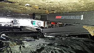
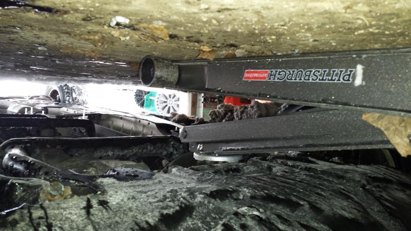
3. Was the bearing press you used the 21 piece set from Harbor Frieght (Pittsburgh Automotive - item#66829 )? I'm just trying to get the right tool before I start.
Thanks in advance!!
Thanks so much for posting! I need to change out a front bearing on my '06 ML350 and have been looking all over the net for this.
I know it's been a while, but I have a couple questions for you.
1. Does the upper ball joint need a seperator to remove? It looks like the top part of the knuckle should just fall away if I remove the nut. Also, when putting it back together, did you use a press or just line it up and tighten?
2. Someone on a different forum mentioned you need to compress the spring before taking off the knuckle. Is this correct?
3. Was the bearing press you used the 21 piece set from Harbor Frieght (Pittsburgh Automotive - item#66829 )? I'm just trying to get the right tool before I start.
Thanks in advance!!
12-13-2018, 08:53 PM
#9
Newbie

Join Date: Dec 2018
Posts: 2
Likes: 0
Received 0 Likes
on
0 Posts
ML 350
ANy chance you could describe just how "bad" the lower ball joints were on your ML? I've got a tiny bit of vertical movement, maybe 1/16 - 3/64" and I wanted to know if I can get away with this for a little while like 10k miles. I have good steering and no wandering on the highway drives straight. If you could reply to : david@duiutah.com Id appreciate it as I rarely check this site Im new to it.


