Mercedes-Benz C-Class and C-Class AMG: Why Does My Car Die Right After Startup?
An engine needs several things to crank and stay running. One of those is electrical energy supplied by the battery. Another is fuel supplied by the fuel pump. A constant supply of air must also be available. Determining what is missing will guide you to a repair in your Mercedes-Benz C-Class or C-Class AMG.
This article applies to the Mercedes-Benz C-Class and C-Class AMG (2007-2014).
When you turn your key to the crank position, your vehicle's starter is powered by the battery and begins to turn your engine at about 300 RPM. During this same time, the vehicle computer references data from sensors, such as the TPS (throttle position sensor) and MAF (mass air flow sensor), to determine the correct amount of fuel to inject into the combustion chamber. The computer also references the crank and cam position sensors. Doing this tells the computer where the piston is at in relation to TDC (top dead center). The computer then has the needed information to correctly time the firing of the spark plugs. If any one of these are missing, your engine may not start.
Materials Needed
- DVOM (digital volt-ohm meter)
- Basic set of hand tools (sockets, pliers, screwdrviers, ratchets)
- A scanner that can view trouble codes (preferably one that can view data)
- Torx screwdrivers or sockets
- MAF and throttle body cleaner
- Propane torch
- Back probes
- Jumper wires
Always check for trouble codes first using an OBDII scan tool. Once you have the code, you can research the number and will have a guide to follow while making the repair.
The testing below applies to both engines. The steps are listed in the format of easiest to hardest to complete.
Step 1 – Perform a visual inspection
Remove the engine cover. The M271 cover is one piece. It is simply pulled straight up and off the engine. The M272 is two piece, and is removed the same way. Remove the front piece first.
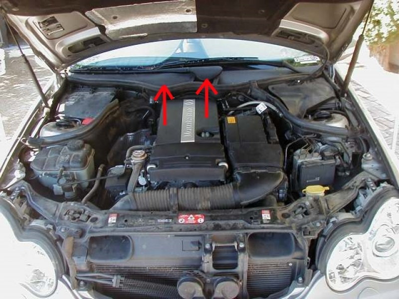
Figure 1. Pull the cover in the direction of the arrows (M271). 
Figure 2. Removing the M272 cover.
Identify the fuel injectors and coil packs on your engine, as they may need to be tested later on.
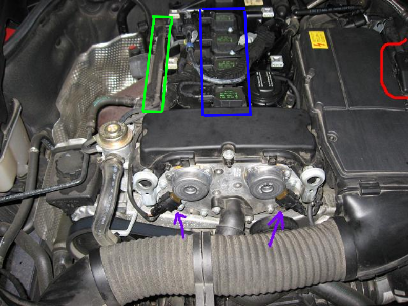
Figure 3. The green box identifies the location of the fuel injectors. The blue box identifies the coil packs (M271). 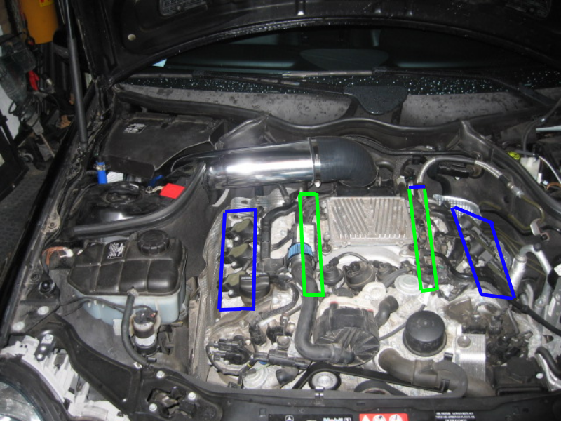
Figure 4. The blue boxes identify the coil packs. The green boxes identify the fuel injectors (M272).
Carefully look at electrical wiring and connectors around the vehicle. If any ground wire(s) connections appear dirty, clean them. Also look for any loose or broken vacuum lines and intake pipes. If there is a fluid leak, make sure your fluid levels are correct. Look to see where the fluid is going. For example, if there is engine oil leaking onto a coil pack, it may be causing a misfire.
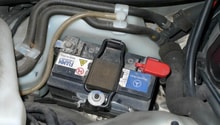
Step 2 – Verify the starting/charging system is operating correctly
A weak battery and/or a weak alternator may be causing your engine to shut off.
If your vehicle actually runs at idle momentarily, that is a good sign because it eliminates some components from the diagnostic process. It is possible for your battery to be at the point where it can no longer hold a high enough charge to keep the engine running. Unfortunately, unless you have a battery load tester, you're limited on testing options. Most automotive parts stores will load test your battery for free.
This process can be done without a DVOM on the W204. Simply use the display in the instrument cluster to watch the battery voltage. By pressing the button to the left on the cluster, battery voltage should appear.
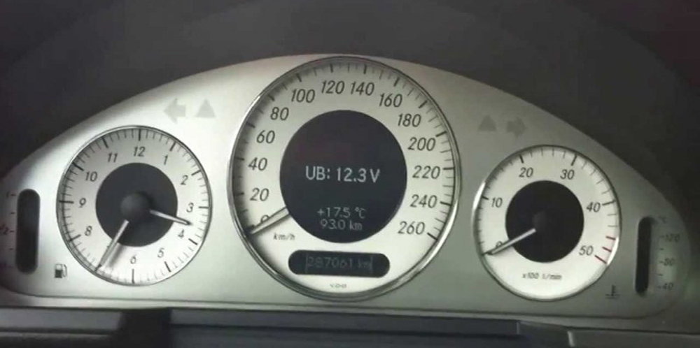
- Connect your DVOM to the battery with the vehicle off. Positive on positive, negative on negative. The reading should be between 12.2 volts to 12.6 volts. If it is lower, you will need to recharge your battery and try again.
- If a weak battery was your problem, be sure to test the alternator. Connect your DVOM in the same way, and raise the engine RPM to 1,500 with all lights/accessories on and running. This includes A/C, headlights, radio, etc.
- Battery voltage should remain between about 14.2 and 14.6 volts if your alternator is functioning correctly.
Be sure to look over the wiring running from your battery to your alternator for any bends, tears in insulation, and corrosion.

(Related Article: Why Does My Battery Keep Dying? - MBWorld.org)
Step 3 – Test the fuel/ignition system
This is a quick test to determine if your fuel system is supplying enough fuel to the engine, or if your spark plugs are firing.
- Spray propane into the air intake stream while cranking the engine. This can be done anywhere on the air intake pipe.
- If the engine now stays running or runs longer, you have a fuel supply issue. You will need to test the fuel pump and injectors.
- It is also possible for the gas in your fuel tank to be of low quality. Pouring in a couple more gallons of fresh gas may cure the problem.
If there is no change in the way the engine runs, then one or more of your spark plugs or coil packs may be faulty.
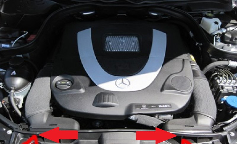
Figure 7. Spray propane into either of the intake openings indicated by red arrows. 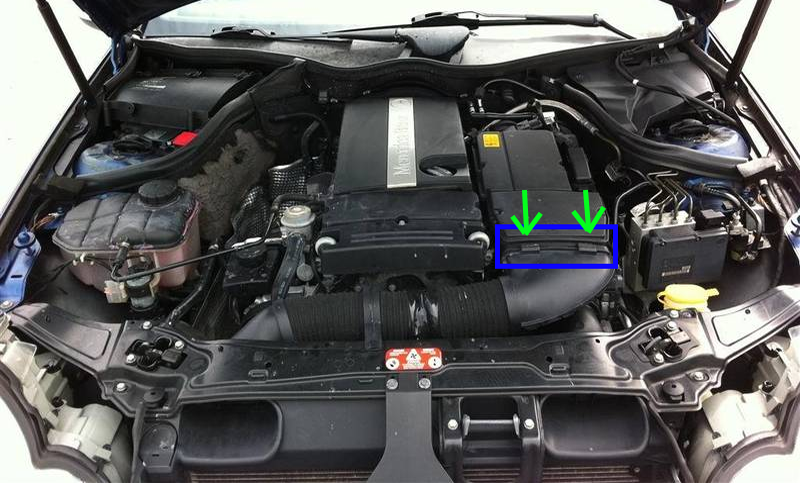
Figure 8. For the M271, first disconnect the intake hose by pushing the two clips (green arrows) and pulling the hose (blue box) off the air box.
Step 4 – Clean the MAF sensor and throttle body
Over time, dirt not captured by the air filter gets trapped in these two areas. This restricts air flow to the engine and distorts the sensor's readings, causing the engine to stall.
Cleaning your throttle body does not require much work once the MAF has been removed on the M272.
- Continue to remove the MAF sensor buy disconnecting the clips holding the intake pipe to the MAF sensor housing and throttle body. There may also be a hose attached to this pipe, but it does not need to be removed if you do not want to remove the intake pipe from the engine bay.
- Once removed, you can manually open the throttle plate with your hand by pushing on it. Use the throttle body cleaner and a rag to clean any dark residue.
On the M271, you will need to loosen the hose clamp (blue box in Figure 9) and pull the hose off of the throttle body (green arrow).
To access the MAF sensor, remove the air box lid. It is held in place by six Torx screws. Once it's lifted out of the way, you will see the MAF sensor at the rear of the air box.

Figure 9. Removing the intake elbow attached to the throttle body. 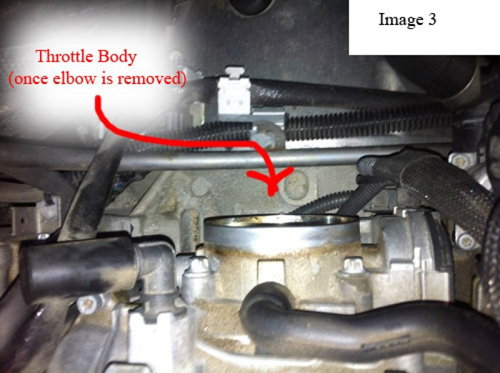
Figure 10. The throttle body. 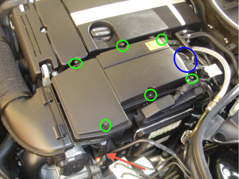
Figure 11. Removing the air lid on the M271. The MAF sensor is indicated by the blue circle. 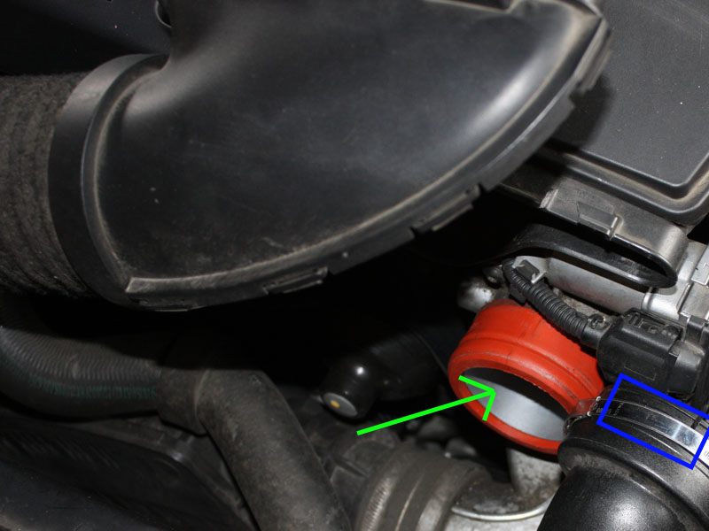
Figure 12. Removing the intake hose (M271).
(Related Article: How to Clean MAF Sensor and Throttle Body - Mbworld.org)
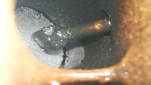
Step 5 – Test the cam and crank sensors
If the sensors are sending the wrong signals to the computer, the engine can stall.
To test the camshaft position sensor, begin by:
- Unplugging the electrical connector and identifying what each pin in the connector is doing.
- Pin 3 supplies 12 volts (battery voltage).
- Pin 2 supplies the hall sensor signal (5 volts).
- Pin 1 supplies ground (less than 0.1 volts).
- Connect your DVOM's positive lead to each pin. Connect the negative lead to battery negative. If the DVOM does show the correct readings, there is a problem with the wiring or the computer itself (short in the circuit).
Now, test the sensor. Attach the connector to the sensor and back probe pin 2.
- Turn the key to the 'on' position (not crank).
- Use a 27mm socket and turn the crank pulley clockwise.
- Watch as voltage rises and falls from close to 0 volts back up to 5 volts. If this does not occur, the sensor will need to be replaced.
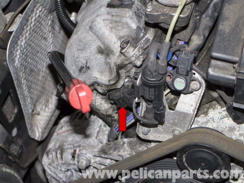
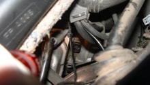
Figure 13. Camshaft position sensor location (M272). 
Figure 14. Testing the 5-volt signal while turning the crankshaft pulley (M272).
To test the crankshaft position sensor:
- Disconnect the connector at the sensor.
- You can use your DVOM to test the sensor directly or attach a set of jumper wires to make things easier. Connect each end of the DVOM to a sensor lead and turn your DVOM to read A/C volts.
- Crank the engine.
- Your DVOM should display 0.5 volts A/C while cranking or else you have a problem with the sensor, computer and/or wiring.
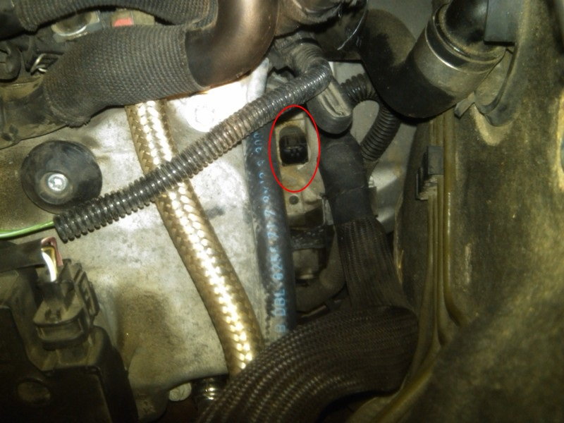
Figure 15. The red circle indicates the crankshaft position sensor (M272). 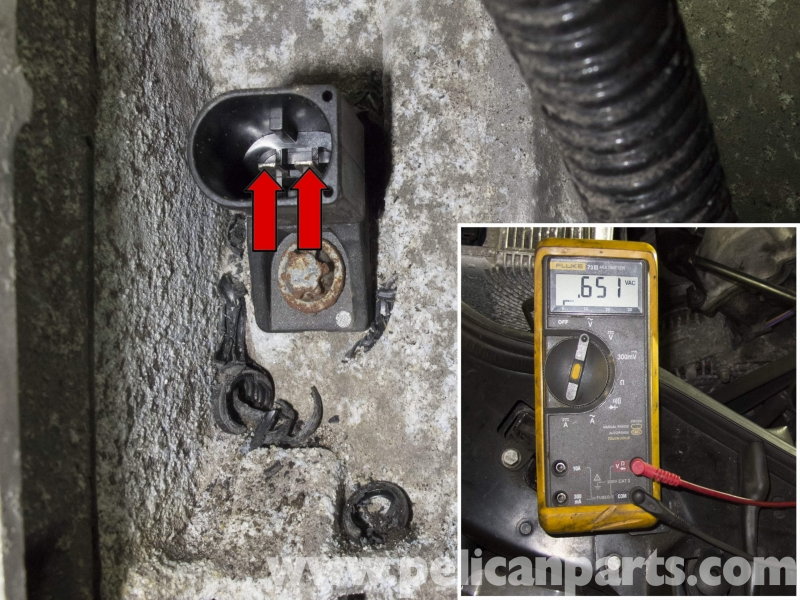
Figure 16. Testing the crankshaft position sensor while cranking the engine (M272).
If these test do not locate your issue, further testing will be required. Access to a lab scope is beneficial when testing for glitches in electrical components. If you decide to take it to a repair shop, let the technician know the testing you have already performed as this will save you time and money.
Related Discussions
- C300 Starts then Dies - MBWorld.org
- C63 Dying Upon Start-up - MBWorld.org
- Funny Engine Noises on Start-up - MBWorld.org
- MAF Replacement - MBWorld.org