Mercedes-Benz E-Class and E-Class AMG: Why is My Battery Not Charging?
The Mercedes-Benz E-Class has one main battery in the trunk and an auxiliary battery in the engine bay. With so many electronic components, things go wrong and could end up draining one of the batteries. Diagnose the problem here.
This article applies to the Mercedes-Benz E-Class and E-Class AMG (2002-2009).
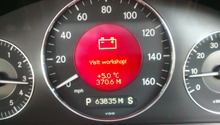
The Mercedes-Benz E-Class batteries do not require maintenance as they are sealed units. The charging system uses a battery control module to monitor the state of charge and turns on the auxiliary battery by powering the auxiliary battery relay when the system's voltage becomes too low. This is accompanied by a red warning screen in the center instrument cluster display that shows a battery accompanied by the phrase "visit workshop."
These codes will save diagnostic time by pointing you in the right direction. Check for OBD2 trouble codes by using the STAR diagnostic tool or an OBD2 scanner. The STAR diagnostic tool is also capable of performing a component level test, which will speed up the diagnostic process.
The following steps are listed from easiest to hardest to perform.
Materials Needed
- OBD2 code scanner
- DVOM
- Basic tool set (screwdrivers, pliers, sockets, and ratchets)
- Digital battery tester
Step 1 – Check the vehicle's voltage level
The w211 system voltage can be viewed from the display on the gauge cluster. Follow these steps to view it:
- Turn your key to position 1.
- Press the R button three times.
- The current voltage level will now be shown.
Once you start your vehicle, the voltage level should read between 13.8 volts and 14.8 volts. A reading in this range indicates your alternator is correctly charging your batteries, and your batteries are holding the charge.
You can also perform an alternator output test by turning on all of your accessories ( lights, radio, defrost, etc.) and revving the engine to 2,000 RPMs. The voltage reading should still be in range. If the voltage level remains below range, then you have a good indication of a faulty alternator. If the voltage rises above and/or drops below range, the voltage regulator may be at fault. The voltage regulator is described more closely in Step 4.
- If you want to monitor each battery's voltage level independently, you will need to test directly at the battery with a DVOM (digital volt ohm meter). Connect your red lead to the positive battery terminal, and connect your black to the negative. This will also be a good time to inspect the condition of the battery terminals for loose connections and corrosion.
- You will find the main battery next to the spare tire by lifting up the carpet in the trunk.
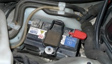
- The auxiliary battery can be found under the HVAC (heating and air conditioning) vent at the passenger side of the engine bay near the firewall.
- To remove the vent, disconnect the clips at the top of the vent. Then remove the nut next to the windshield washer fluid cap.
Now is also a good time to check for a parasitic drain when the vehicle is off. Follow these steps to complete this:
- Wait twenty minutes after the key has been removed from the ignition.
- Move your DVOM leads to the correct ports on your DVOM to read amps, and move the dial to the DC amps position.
- Disconnect either the positive or negative battery cable (you will do this for each battery) and place the positive lead of your DVOM on the battery post. Place the other lead on the battery cable.
- You are now reading current. If this reading is not zero, then there is a parasitic draw on your system. It must be repaired before replacing the batteries.
You will need to locate the multiple fuse boxes in the vehicle and test each fuse to find which circuit the draw is located on. With the help of a wiring diagram, you can narrow down the cause. Read through Step 7 for more information on fuses/relays.

Figure 1. The main battery located in the trunk. 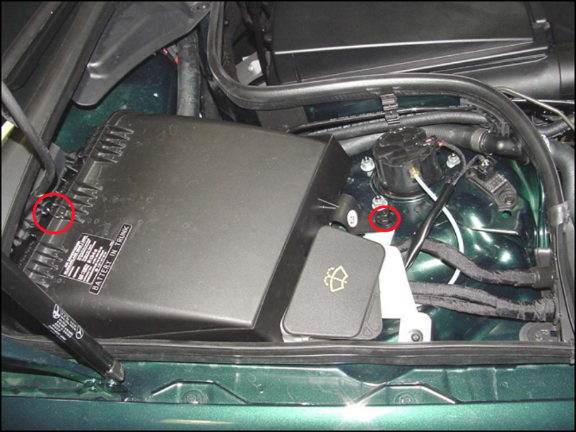
Figure 2. The red circles indicate the clip and nut holding the HVAC vent in place. 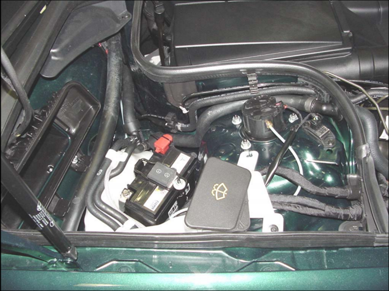
Figure 3. The auxiliary battery.
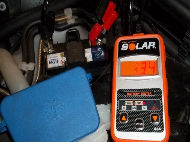
Step 2 – Test the batteries
Mercedes-Benz does not advise load testing the factory AGM (absorbed glass mat) batteries. Instead, they recommend the batteries be tested with a digital tester, such as the Midtronics MCR 717 or similar. This tester measures battery conductance by inducing a small A/C voltage into the battery and then reading how the battery's current responds.
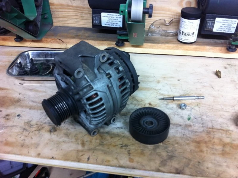
Step 3 – Check the condition of the alternator belt and pulley
A problem with the alternator belt or pulley may cause the belt to slip or the pulley to seize. This will result in a decrease of alternator output.
Visually check the condition of the belt. If the belt is easy to stretch or has cracks, replace it.
Start the vehicle, watch the alternator pulley for a wobbling motion, and listen for any unusual noises. The bearings inside of the pulley may be bad if these conditions are noticed.
Step 4 – Inspect the voltage regulator
The voltage regulator keeps the charging system's current flow at the proper levels. It is designed to read and convert the voltage supplied from the batteries, then read the output voltage to determine if the alternator's output is correct.
There are two electrical contacts on the voltage regulator that wear and become shorter over time. Once they get too small, continuity is no longer available and charging problems will result.
The voltage regulator is mounted to the backside of the alternator and is held in place by Phillip-head screws. Make sure the connector attached to the voltage regulator is fully snapped into place.
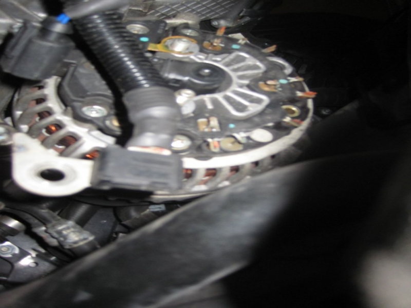
Figure 6. You can see the black voltage regulator on the back of the alternator. 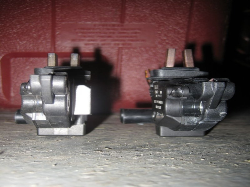
Figure 7. A comparison of old vs. new voltage regulator contacts.
Step 5 – Inspect the battery control module
The battery control module is located in the trunk next to the battery and spare tire. It monitors the voltage level of both batteries and the alternator and sets DTCs (diagnostic trouble codes) in the event of a failure. It also controls the auxiliary battery relay.
The battery control module communicates on a CAN (controller area network). A diagnostic scanner must be used to communicate with the control module to test it for errors.
If you have a wiring diagram available, you can locate the power and ground for the module and test that both are present.
You will see several connectors and large gauge wires connected to the module. Verify these are tight and secured into place. Wiggle the module to make sure it's securely fastened to the body.

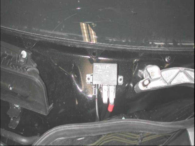
Step 6 – Inspect the auxiliary battery relay
The auxiliary battery relay is controlled by the battery control module. It is powered on when the auxiliary battery voltage level becomes low. It's located in the engine bay against the firewall. When facing the engine from the front, you will see the relay to the right of the HVAC vent. If you tested the auxiliary battery and it passed, you have an indication of a faulty auxiliary battery relay. The relay has three wires connected to it. These route to the battery control module and batteries. Make sure these wires are connected securely to the relay. The STAR diagnostic tool has a test designed to determine if the relay is correctly working.
Step 7 – Inspect the fuses/relays
There are three seperate fuse/relay boxes. They are named F32 ( front pre-fuse box), F33 (rear pre-fuse box), and the F34 (interior fuse box). The F32 is located in the interior on the passenger side footwell area. It is mounted against the firewall. The F33 is located directly behind the main battery in the trunk. The F34 is found to the left of the instrument cluster.
Hyperlinked in the discussions section at the bottom of the article is a list of fuses/relays showing their associated circuit and amperage rating. Use this to test for parasitic draw and to locate any blown fuses associated with the charging system. If you suspect a fuse is blown (you will see the metal strip inside of a blade type fuse burnt and broken) switch your DVOM to read continuity and connect each lead to the fuse blades. If there is no continuity, the fuse will need to be replaced.
There is also a fuse next to the auxiliary battery known as the polyswitch fuse. This fuse senses the voltage seen by the battery control module.
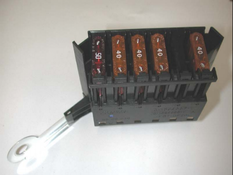
Figure 10. Blade fuses. 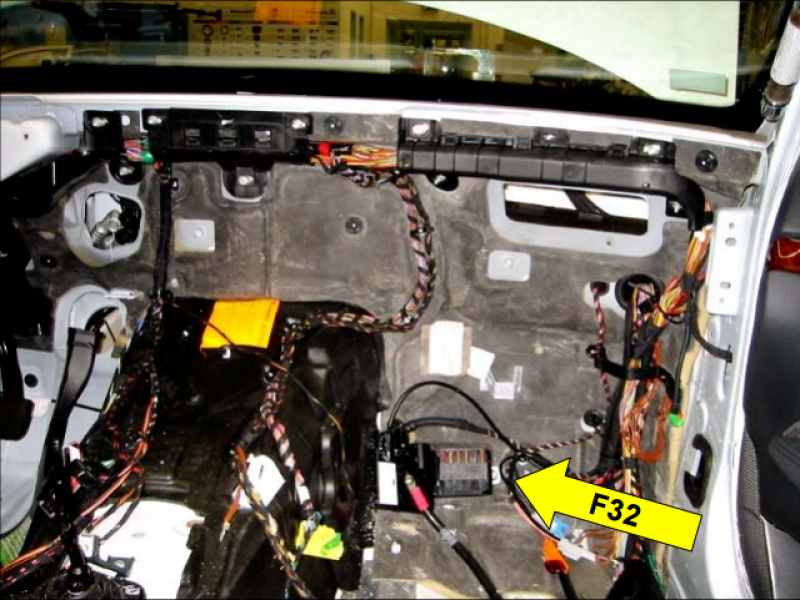
Figure 11. The F32 fuse box. 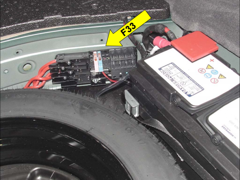
Figure 12. The F33 fuse box. 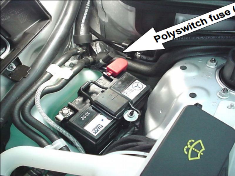
Figure 13. The polyswitch fuse.
Related Discussions
- Red Battery Message - MBWorld.org
- E320 Battery Drain Forum Discussion - MBWorld.org