Mercedes-Benz E-Class and E63 AMG: Why Does My Car Turn Over But Won't Start?
An engine requires four main ingredients to run: ignition, fuel, air, and compression. With the right equipment, finding out which is missing is not too difficult.
This article applies to the Mercedes E-Class and E63 AMG w211 (2002-2009).
Understanding how your vehicle's systems work to create a running engine will help you while diagnosing. This article will begin with a primer on the functionality of your engine.
Ignition
The engine must have a correctly timed spark. Spark is exactly what is sounds like, the firing of the spark plugs in the cylinder will create combustion. Here is what you need for an engine to spark:
- The cam and crank position sensors must be functioning correctly. If not, the computer will not know when to fire the spark plug.
- The computer itself must be able to send the signal to the ignition coils. The battery voltage is important here because if it becomes low, the computer may malfunction.
Fuel
You must have an adequate supply of fuel going to the engine. In a crank/no start this includes:
- A fuel pump capable of pumping the correct amount of fuel
- Power running to the fuel pump to energize it
Air
The correct amount of air must be available to the engine. A restriction in the intake can cause a crank/no start. Some causes are:
- A clogged air filter
- Debris trapped in the intake passage
Just as important as air entering the engine, is exhaust leaving the engine at the same rate. Examples of an exhaust restriction are:
- A kinked exhaust pipe
- A clogged catalytic converter
- A clogged muffler
Compression
Mechanically, your engine must be in good condition. Your engine will not start if you have low compression. In short, compression is the force in the cylinder provided by the crankshaft moving the rods and pistons. Causes of low compression are:
- Worn or broken piston rings
- A hole in the piston or valves
- Bent or burnt valves
- A broken or jumped timing belt or chain
This article will guide you through the testing process for each system, and more. The test will be listed in order of easiest to perform to the hardest. Checking for codes and performing a visual inspection will always be your first step. Once you have the code, you can research and will have a direction for your diagnosis.
Materials Needed
- A basic set of hand tools (ratchets, extension, sockets, screwdrivers, pliers)
- Spark tester
- Fuel pressure tester
- Compression tester
- Exhaust system backpressure gauge
- A digital volt-ohm meter (DVOM)
- 02 sensor socket
- Propane
Step 1 – Perform a visual inspection
- Remove the engine cover.
- Carefully look at electrical wiring and connectors around the vehicle. If any ground wire connections appear dirty, clean them. Also, look for any loose or broken vacuum lines and intake pipes.
- If there is a fluid leak, make sure your fluid levels are correct. Look to see where the fluid is going. For example, if oil is leaking onto the crankshaft position sensor, it may be disrupting its connection.
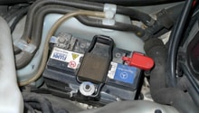
Step 2 – Verify your starting/charging system is operating correctly
A weak battery and/or a weak alternator may be causing your engine to not run. Be sure to re-check the condition of your battery if it is determined to be operating correctly, while you perform the test. Repeated engine cranking will drain the battery.
The battery may not be able to supply enough power to the starter. If the engine is not turning at the correct rpms (minimum about 400), it will not run. The two best options to test your battery's condition are checking the charge level and a battery load test. Most automotive parts stores will load test your battery for free.
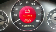
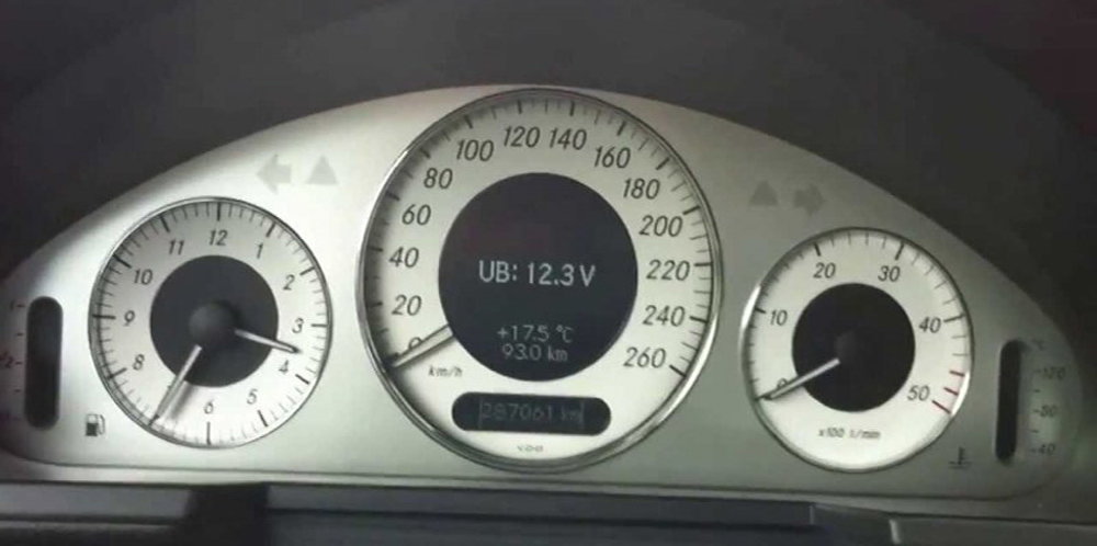
This process can be done without a DVOM on the w211. Simply use the display in the instrument cluster to watch the battery voltage. By pressing the button to the left on the cluster, battery voltage should appear.
Using a Digital Volt-Ohm Meter (DVOM)
- Connect your DVOM to the battery with the vehicle off. Positive on positive, negative on negative. The reading should be between 12.2 volts to 12.6 volts. If it is lower, you will need to recharge your battery and try again.
- If a weak battery was your problem, be sure to test the alternator. Connect your DVOM in the same way, and raise the engine rpm to 1,500 with all lights/accessories on and running. This includes A/C, headlights, radio, etc.
- Battery voltage should remain between about 14.2 and 14.6 volts if your alternator is functioning correctly.
Be sure to look over the wiring running from your battery to your alternator for any bends, tears in insulation, and corrosion.

Step 3 – Test the ignition system
The simplest method to test the ignition system, other than with a scan tool, is to use a spark tester. Performing a spark test will also confirm the integrity of the wiring between the ignition coils, and computer. A properly timed spark also confirms your cam and crank signals are functioning correctly.
- Simply remove a coil pack from the engine, and insert the spark tester into the coil pack. Make sure the clip of the spark tester is on a grounded section of the engine (a metal bracket attached to the block, for example).
- Attempt to start the engine, and see if spark is present.
- If no spark is present, swap coils from another cylinder. If there is still no spark on that cylinder, then there is a problem with the wiring, computer, or cam and crank sensors. Very rarely do multiple coils go bad at the same time.
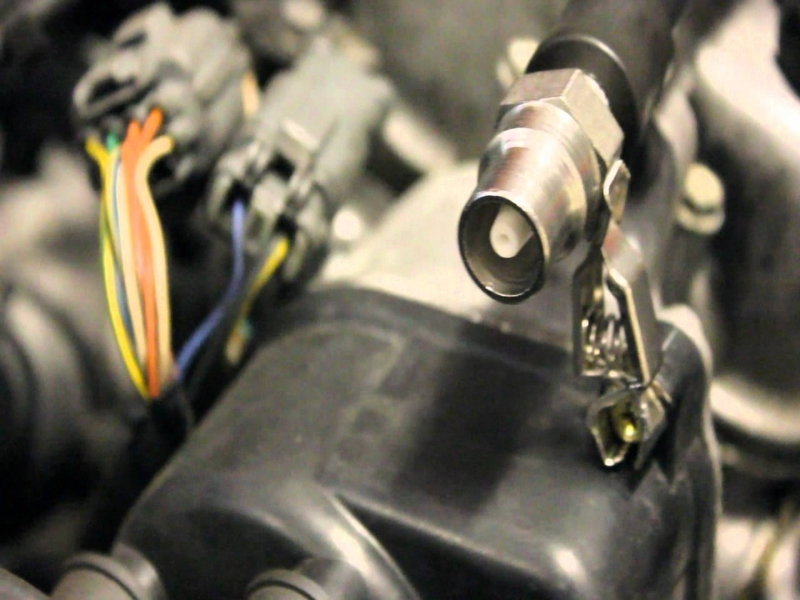
Figure 4. A spark plug tester has been installed into a plug wire. 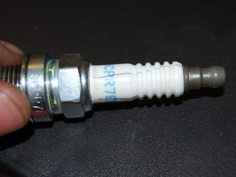
Figure 5. You can see the cracks on this spark plug.
Step 4 – Test the cam and crank sensors
If the sensors are sending the wrong signals to the computer, the engine will not start. To test the camshaft position sensor, begin by unplugging the electrical connector and identifying what each pin in the connector is doing:
- Pin-3 supplies 12 volts (battery voltage).
- Pin-2 supplies the hall sensor signal (5 volts).
- Pin-1 supplies ground ( less than 0.1 volts).
Connect your DVOM's positive lead to each pin. Connect the negative lead to battery negative. If the DVOM does show the correct readings, there is a problem with the wiring or the computer itself (short in the circuit).
Now, test the sensor. Attach the connector to the sensor and back probe pin-2.
- Turn the key to the 'ON' position (not crank).
- Use a 27mm socket, and turn the crank pulley clockwise.
- Watch as voltage rises and falls from close to 0 volts back up to 5 volts. If this does not occur, the sensor will need to be replaced.
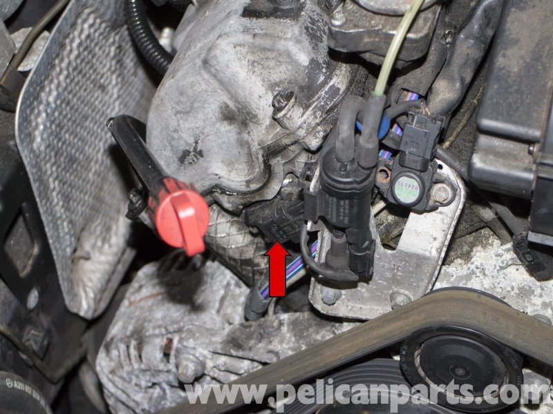
Figure 6. Camshaft position sensor location. 
Figure 7. Testing the 5-volt signal while turning the crankshaft pulley.
Step 5 – Test the fuel pump/system pressure
Pro Tip
Before testing fuel pressure, If the fuel filter has not been replaced recently, do so as it may be acting as a restriction.
This is a quick test to determine if your fuel system is supplying enough fuel to the engine, or if your spark plugs are firing.
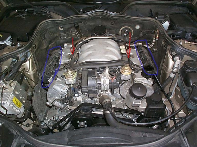
- Spray propane into the air intake stream while cranking the engine. This can be done anywhere on the air intake pipe.
- If the engine now starts, you have a fuel supply issue. You will need to test the fuel pump and injectors.
- It is also possible for the gas in your fuel tank to be of low quality. Pouring in a couple more gallons of fresh gas in may cure the problem.
If there is no change in the way the engine runs, then one or more of your spark plugs or coil packs may be faulty. However the case of a crank/no start condition, the computer and/or its associated wiring is more of a concern.
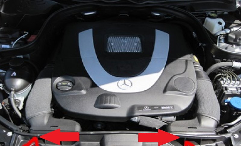
Figure 8. Spray propane into either of the intake openings indicated by red arrows. 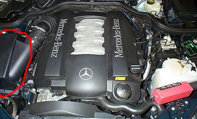
Figure 9. If your w211 has this engine, you can remove the air box lid and spray propane into the air intake hose.
Testing Fuel System Pressure
- First, release the pressure from the system.
- Remove the yellow fuel pump fuse. The fuse/relay box is located at the left side of the trunk next to the CD changer.
- Start the car and let it run until the engine dies.
- Now, locate the fuel system pressure test port and remove the plastic cap.
- Install your fuel system pressure tester.
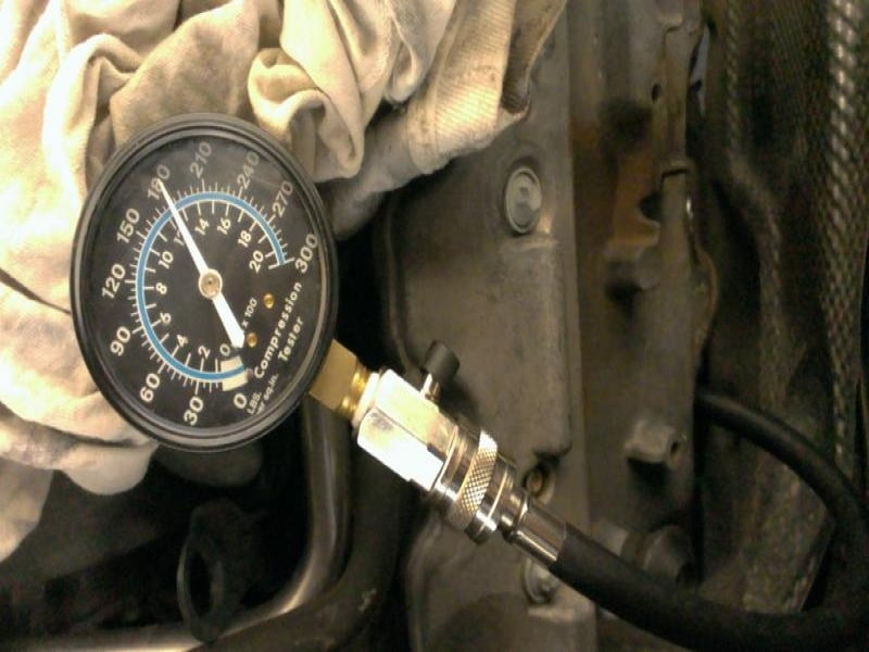
- Re-install the fuse and turn the key to the 'ON' position (not crank). Then, crank the engine and record the reading on the gauge. The pressure on the gauge should read between 35 psi and 45 psi. Turn the engine off, and watch the gauge over a period of 30 minutes to see if pressure is holding in the system. If pressure bleeds off lower than about 25 psi, then the fuel pump/regulator assembly is leaking and will need to be replaced.
If the system does not build any pressure, there may also be an electrical problem with the fuel pump circuit. Use your DVOM to test the fuel pump fuse and relay for 12 volts at the fuse/relay box. If power is available at both locations and the fuse as well as relay test okay, begin checking the connector near the fuel pump.
- Begin testing by removing the rear seats. There are plastic clips that you must push at the front of the seat to remove them. Then, remove the carpet below the seats by pulling up. You will hear a pop as the plastic clips at the corners of the carpet separate.
- You will see two covers held in place by six 8mm fasteners. Remove the fasteners to the cover on the driver's side and lift it up.
- You will now have access to the fuel pump connector.
- To test: set your DVOM to read DC Volts. Connect the red lead to the power wire (usually red, but a wiring diagram will be helpful). Connect the black lead to a known good ground (anything metal in the car connected to the chassis). If there are 12 volts present, you have power going to your fuel pump.
- Now test the ground circuit for the fuel pump. Keep the red lead on the power wire, and move the black lead to the brown wire. Once again, the ground wire may not be brown, so access to the wiring diagram if needed. If 12 volts are present, the ground circuit is functional. If not, there is a short somewhere inside the ground circuit.
- Replace the fuel pump if there is both power and ground available.
Click to enlarge the figures below:
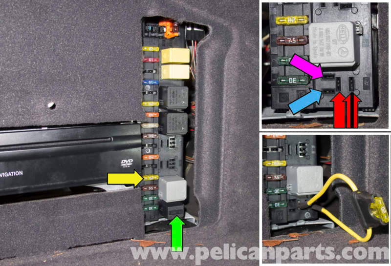
Figure 10. The fuel pump fuse/relay box. The relay is indicated by the green arrow, and the fuse by the yellow. 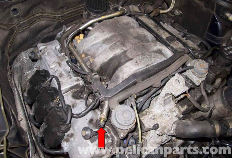
Figure 11. The fuel pressure test port. 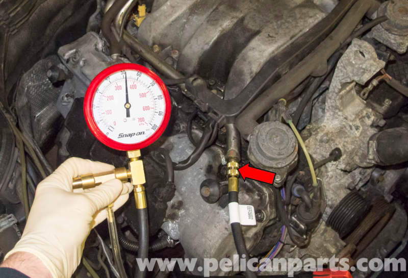
Figure 12. The fuel pressure gauge has been connected. 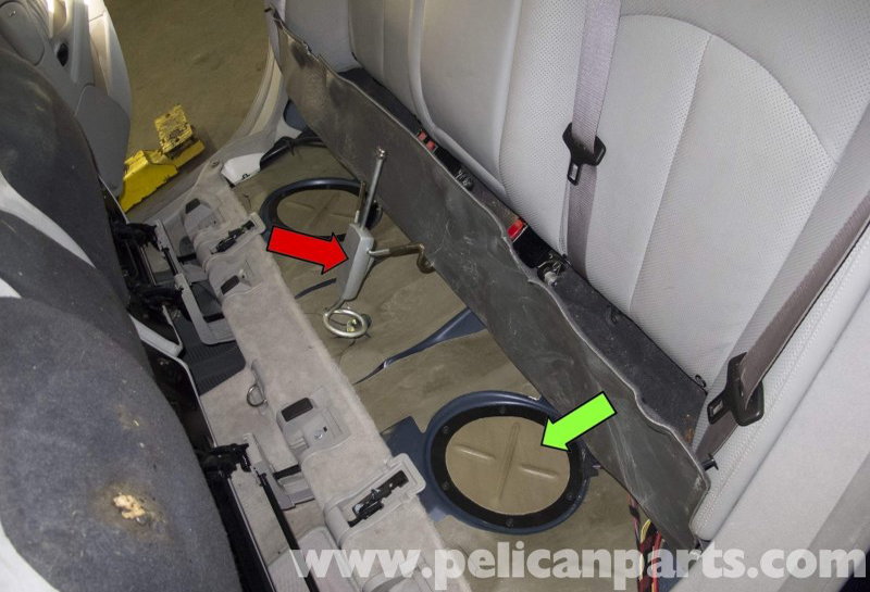
Figure 13. The green arrow indicates the cover that must be removed to gain access to the fuel pump connector. 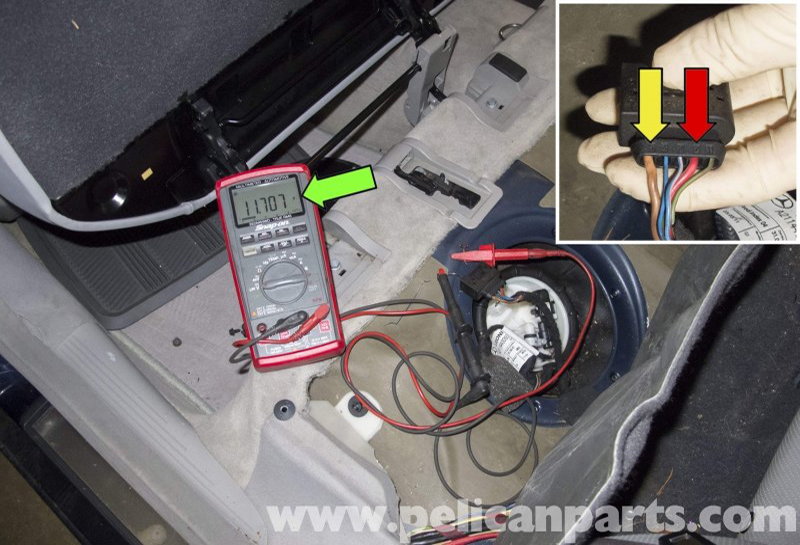
Figure 14. Using a DVOM to test for power and ground at the fuel pump connector.
Pro Tip
You should hear a humming noise coming from the fuel pump for about three seconds after the key is turned to the 'ON' position. Remove the rear seats, so the hum is easier to hear. If there is no humming sound, the fuel pump is not turning on.
Step 6 – Check for a restriction in the intake
Remove the air filter box and intake piping completely until you reach the throttle body.
There are two different ways your intake system may be routed depending on your engine. The first system has two filters. Both filters are directly beneath the engine cover. The other has an air box on the passenger's side of the engine bay. Remove the top cover of the air box by removing any fasteners/clips holding it in place, and loosening clamps holding it to the intake pipe. Clean or replace the air filter(s).
You will want to continue removing the rest of the intake piping until you reach the MAF sensor. If the piping is clear, your intake is unrestricted.
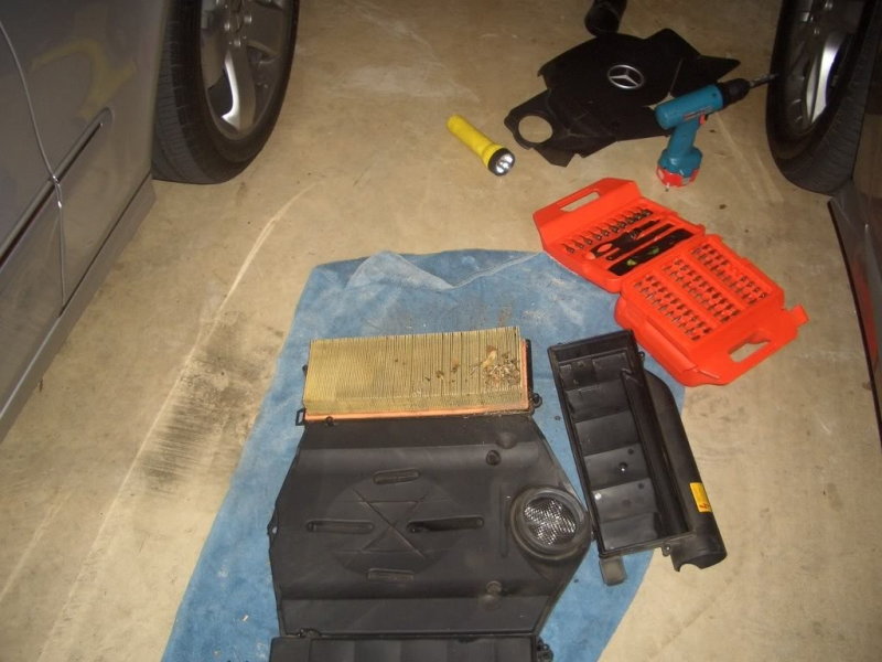
Figure 15. The air filter is being replaced. 
Figure 16. Continue removing the intake pipe once the air box and filter have been cleaned.
Step 7 – Perform a compression test
Low compression may cause a no start. To perform a compression test:
- Remove the fuel pump fuse, and bleed off the system pressure.
- Now, remove a spark plug and install the compression tester into the port.
- Crank the engine for four revolutions with the throttle held open. Record the reading on the compression tester.
- Do this for every cylinder, and compare the results. All cylinders should be within 20% of each other.
If you have a compression problem, you can determine if the piston rings are the cause by injecting a small amount of oil into the cylinder through the spark plug tube. If compression increases, you have a piston ring sealing problem on that cylinder.
Step 8 – Perform an exhaust system back pressure test
You will need to remove an upstream 02 sensor, and install your exhaust system back pressure gauge.
- Safely raise and support the vehicle. Refer to the Related Article.
- You will need to test both exhaust banks. Choose which upstream O2 sensor you want to remove first.
- Once an O2 sensor is removed and the gauge is installed, crank the engine while observing the reading on the gauge.
- If the gauge registers over 1.5 psi, you have excessive exhaust back pressure.
- You can perform the same test on the rear O2 sensors to determine if the catalytic converter is the cause of your back pressure. If the readings drop below 1.5 psi, you will need a new converter(s).
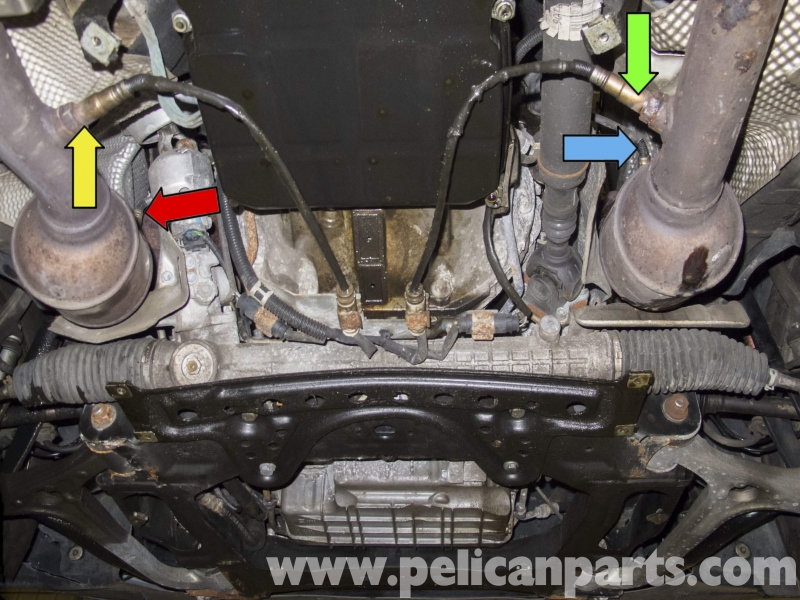
Figure 18. The red and blue arrows indicate the upstream 02 sensors. The yellow and green are the downstream. 
Figure 19. How to install the back pressure gauge.
If you decide to take your vehicle to a professional garage, keep a list of the testing you have performed and give it to the technician. This will save you both time and money.
Related Discussions, and Site
- Dirty Air Filter -MBWorld.org
- Cranks Won't Start - MBWorld.org
- Solving No-Start Problems - ErictheCarGuy