When you click on links to various merchants on this site and make a purchase, this can result in this site earning a commission. Affiliate programs and affiliations include, but are not limited to, the eBay Partner Network.
2012 C63 with P30, LSD, and EES Supercharger, 1959 Plymouth with Viper V10 and Tremec 6sp
ESS Supercharger DIY Installation
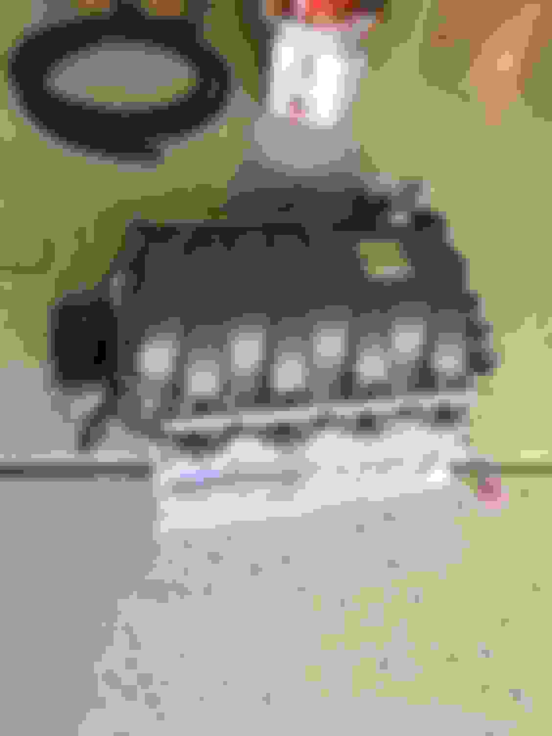
I received my ESS Supercharger last week and started the installation over the weekend. I will post my pictures and lessons learned for any of you who want to do the installation yourself. My car is completely stock including air filters and I did a Pre Installation dyno test of the car and I will have a Post installation dyno done on the same machine. I will post pictures with comments as I make progress. My first impress as I opened the box and inspected the parts is that this is a very high quality kit with all the hardware and hoses as good or better than OEM quality. Very different than my experience with a Paxton kit about 15 years ago! The first step is to remove the intake manifold and that is pretty straightforward.
Three dyno pulls. Stock motor and tune, P30
Remove air boxes and reach behind to undo the plastic tab on each side of the rear air intake. Make sure you vacuum out all the dirt around the 10 intake bolts before you remove anything. You can leave all the FI parts in place. Unplug all the vacuum hoses front and rear and the wiring pugs in the front, and the fuel line.
There you have it! Now you need to remove the throttle bodies
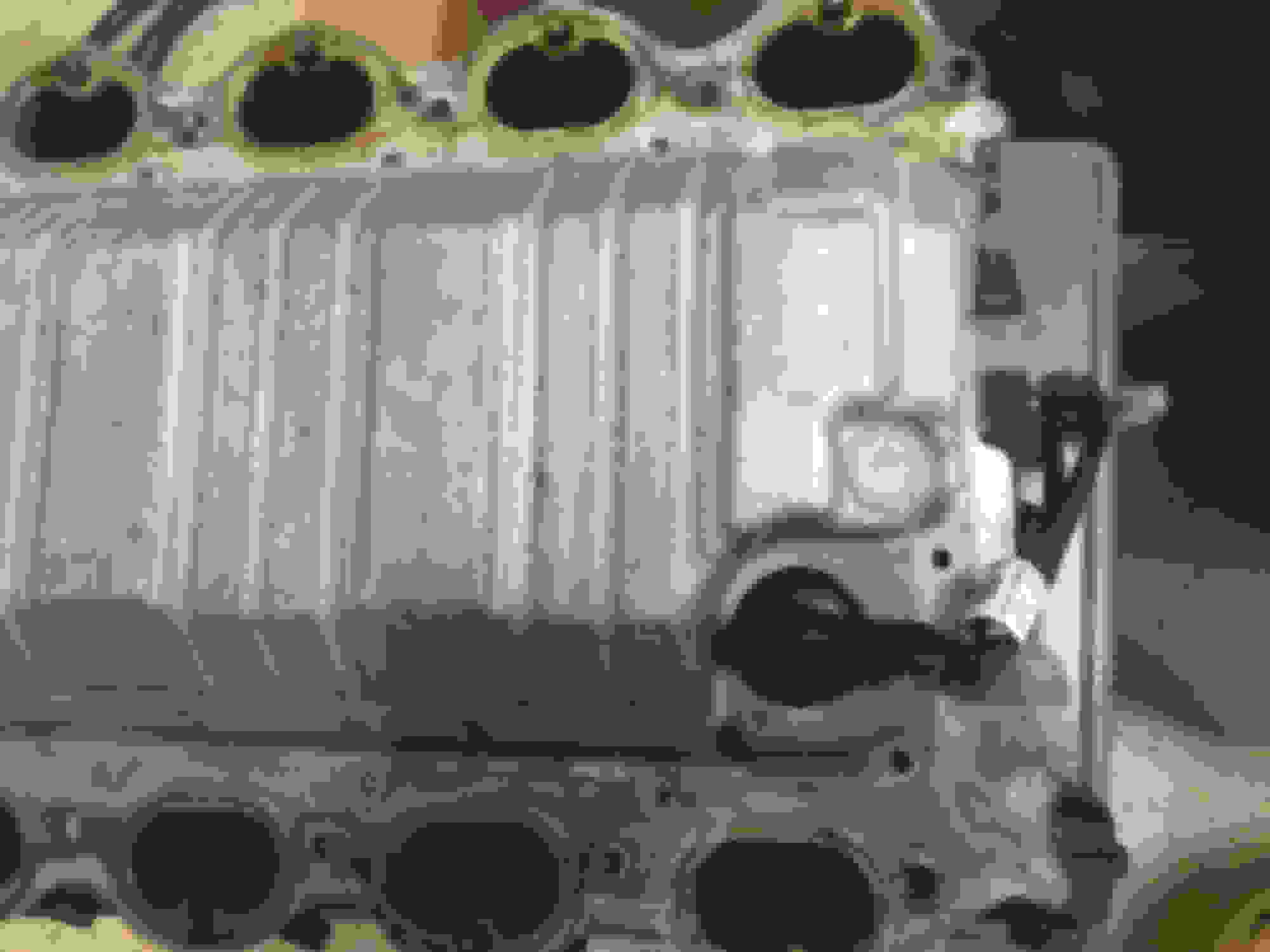
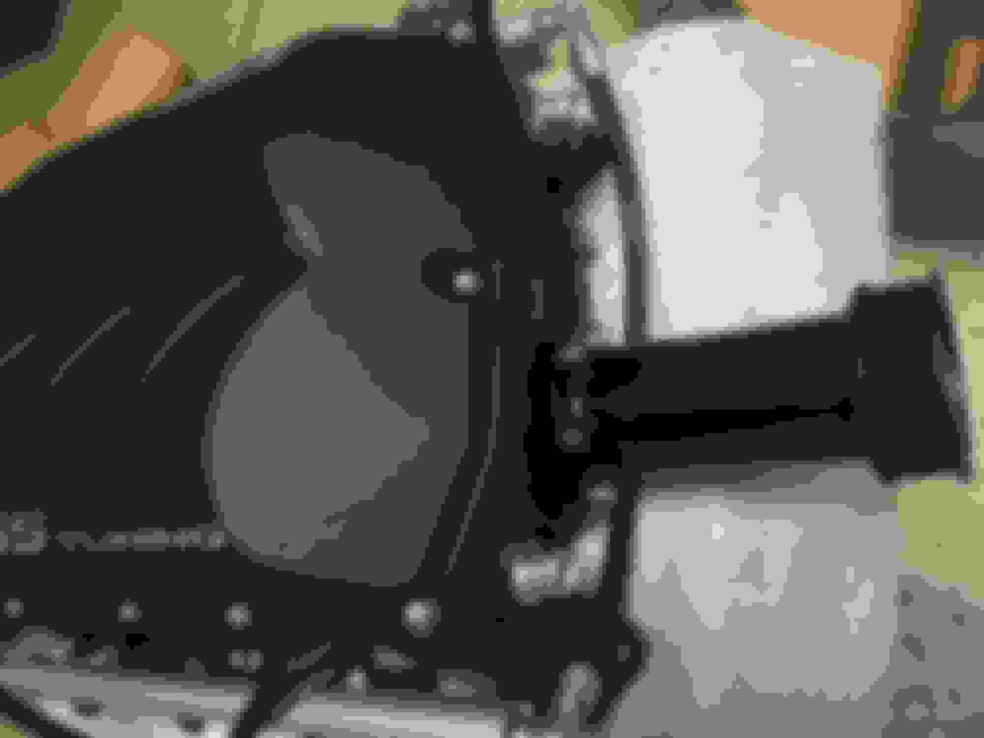
Remove the screws and the bottom comes off. You need to feed the rubber grommet through the pan
There are the two throttle bodies. You need to remove the plastic surround to get at the 4 bolts mounting each TB. The plastic rings are held on by two plastic clips you need to release with your fingers or a small screwdriver.
2012 C63 with P30, LSD, and EES Supercharger, 1959 Plymouth with Viper V10 and Tremec 6sp
More progress!
I have had other chores but have still made good progress. The supercharge unit is now ready to put on the engine after I finish installing the new power steering reservoir and the tank and pump for the intercooler. I thought the PS tank was plastic but it is TIG welded aluminum with the nice black coating. I have been very impressed with the quality of the kit and the hardware. Here are some updated pictures of my progress.
Throttle Bodies, new injectors and fuel rails installed
Drive snout installed with the 6# pulley. The 8# is also included in the kit
2012 C63 with P30, LSD, and EES Supercharger, 1959 Plymouth with Viper V10 and Tremec 6sp
Thanks. I installed the coolant and PS reservoir behind the front right headlight and both fit right in without problem. They look like factory parts. I will post more pictures later. I am going to install an ESC catch can before installing the SC and am trying to figure out where to mount it. I will take lots of pics as I think many are interested in a less costly can than Weistec. After I figure out the mounting I can drop in the SC!
2012 C63 with P30, LSD, and EES Supercharger, 1959 Plymouth with Viper V10 and Tremec 6sp
Ready to install SC Unit
When installing the drive snout line up the three drive dowels and gently tap the shaft and it slips right on
View from the rear. The brake vacuum plugs in green, the other hard vacuum line in orange, the right nipple fits hose to the adjacent bypass valve, left nipple takes hose to front of engine, and I have plugged the intake air temp sessor into its hole
2012 C63 with P30, LSD, and EES Supercharger, 1959 Plymouth with Viper V10 and Tremec 6sp
The factory PVC after removing the hose
ESC catch can
Inside filter and dip stick for can
PVC and hose before mounting SC
PVC hose on supercharger
I had to use my engine hoist to install the SC as my old back just wasn't strong enough
Finally settled in place! Now I can hook of the wiring and hoses and put things back together before I remove the front bumper to install the intercooler radiator
Made some good progress yesterday and got the unit on the engine! Took me some extra time to figure out where to put the catch can. Will place it on the right side next to the new coolant tank. I purchase an ESC can that appears to be very high quality and similar to the Weistec. I used 3/4 ID hose as that is the closest fit to our PCV valve fittings. I am working on it again today so will have more pictures.
!
Kick *** thread, always wanted to do a supercharger to my w204 but didn't. Will watch along with the rest of us, keep up the great post and information. Looking forward in seeing some awesome increases.
2012 C63 with P30, LSD, and EES Supercharger, 1959 Plymouth with Viper V10 and Tremec 6sp
Originally Posted by ritalin
Nice job!
Did you have a part number for the ecs catch can? Nothing seems to come up on their site.
It is from ESC Tuning and the catch can part number is 2816993. They also have a universal mounting kit 2918376. They seem to be very high quality parts and should be a nice addition to the supercharger.
Awesome thread!
Will subscribe to keep up with your progress. Really nice of you to share all these details.
Now waiting to see the outcome on the Dyno!
Congratulations
2012 C63 with P30, LSD, and EES Supercharger, 1959 Plymouth with Viper V10 and Tremec 6sp
Originally Posted by Jasonoff
If starting a weekend job 3 weeks ago is great progress, I wanna work for East Coast Euro.
No offence Jimbo, we all know this is a side project.
Yes, I am lucky to get one day a week to work on this project. And I do want to thank Ahmad at East Coast Euro for his great advice whenever I have had a question when the directions were not clear.
Yes, I am lucky to get one day a week to work on this project. And I do want to thank Ahmad at East Coast Euro for his great advice whenever I have had a question when the directions were not clear.
2012 C63 with P30, LSD, and EES Supercharger, 1959 Plymouth with Viper V10 and Tremec 6sp
Thanks for the FI harness tip. Ahmad from East Coast Euro suggested that when I ordered the kit so I made them while I was waiting for delivery. The lowest price I found was $8 per harness but $64 well spent. I soldered on the included pigtail and covered with marine grade heat shrink with the glue. I am using the stock air boxes and have to trim the inner edges to clear the supercharger. I will have time to work on it this weekend so will have more pictures. Will also mount the catch can and run the hoses and hopefully finish up in the engine compartment. I installed the serpentine belt which is always a lot of fun.
Based on the image in post #10, the IAT sensor appears to be reading the air temp directly after the throttle bodies. Is that the position ESS recommend?
If my interpretation of the image is correct, it would be wise to relocate the sensor to be after the charge air coolers - place it close to the head ports. If not, the ECU/tune is only going to recognise the IAT pre-boost which would be way less than ideal - the IAT's after the coolers is the relevant temperature... especially with a twin-screw (unless you are willing to melt engine internals).
 04-23-2018, 10:57 AM