When you click on links to various merchants on this site and make a purchase, this can result in this site earning a commission. Affiliate programs and affiliations include, but are not limited to, the eBay Partner Network.
Step-by-step DIY: 2017 GLS 63 Front Brake Rotors and Pads
DISCLAIMER This post is for information only. Your vehicle’s braking system is safety-critical, and therefore requires extra attention and diligence when any maintenance operations are performed upon it. Furthermore, this particular maintenance operation requires the vehicle to be jacked up. If you are not familiar with and comfortable with jacking and stabilizing your vehicle, and with the use of a torque wrench, please do not attempt this operation. You assume all risks associated with working on your own vehicle, and do not hold me liable for any damages. Having this work done by a qualified professional is recommended.
ACKNOWLEDGEMENTS This post benefits from the good efforts of several MBWorld list members. The format is loosely based on an unrelated post by @Keep ; I don’t know if @Keep is the originator of this format, but it is very useful. @cyclrder, @cm60k , @chassis , and @threeMBs have also provided helpful information that is incorporated into this post.
APPLICABLE M-B WORK INSTRUCTIONS (Attached Below)
Remove/install front axle brake caliper (AR42.10-P-0070GZ)
Remove/check/install front axle brake pads (AR42.10-P-1610CMG)
Remove/install brake disc (AR42.10-P-0220GZ)
PARTS
Brake Pads (qty: 1 set of 4 pads) A-008-420-20-20 (or EBC Redstuff DP31939C )
Rotor (qty: 2 ea) A-166-421-05-12 (or Brembo 09.B805.11 or Zimmermann Coat Z 400 3698 20)
Caliper to Caliper Support Bracket Mounting Bolts A-003-990-79-05
Caliper Support Bracket to Steering Knuckle Mounting Bolts A-019-990-56-01 (not needed if you use the A-003-990-79-05 bolts -- see discussion below)
Short bungee cord or wire hanger to hold brake caliper body
Safety glasses
Shop rags and floor protection
OPTIONAL TOOLS
˝” impact wrench for wheel lug bolt removal
1/4" impact driver
Angle grinder or drill with wire wheel
Auxiliary lighting
Figure 1: Tools used for this operation
PREPARE THE VEHICLE FOR SERVICE
0. Optional: Raise vehicle to maximum height (Airmatic) (Note: I need to do this in order to get my Unijack jackstands under the vehicle. Skip this step if you use a shop lift, etc.) a. With engine running, depress vehicle height button on center console. Multifunction display will show vehicle “raising”. b. Once “raising” indicator extinguishes, turn off engine.
1. Remove brake fluid to allow back-filling into brake fluid reservoir a. Raise hood. b. Remove plastic cover above left suspension shock tower. (Note: There are no clips or other features that require special actions. Just lift up on the cover. You may need to move the hood underside rubber seal a bit to allow the cover to come off.) c. Clean area around brake fluid reservoir cap with a shop rag. d. Remove cap to brake fluid reservoir and then remove filter ring inside the reservoir neck. e. Remove brake fluid down to the “MIN” line. Use brake fluid vacuum bulb or siphon line to remove brake fluid into a clean container that can be sealed to keep moisture and contaminants out. (Note: You will add some of this fluid back after the new pads have been installed.)
2. Lift or jack vehicle (Note: there have been many threads on MBWorld about the challenges of jacking M-B unibody vehicles. For those of us not blessed with a vehicle lift, the challenge is that M-B provides only one single jacking point for each corner, so there is no good way to jack the vehicle and then emplace a jack stand. I use Powerbuilt 620471 Unijack 6000 lb. combination bottle jack/jackstands to address this issue. They fit under the vehicle (barely) when the extensions are removed and the Airmatic suspension is set to its maximum height. Emplace them very carefully to straddle the plastic jacking point. SAFETY POINT: I do not recommend using a floor jack with no jackstand to support the vehicle while you are working on it. Don’t make this mistake — if your floor jack fails, the consequences to your vehicle and possibly your body are SEVERE!) a. If you don’t have an impact wrench, now is the time to slightly loosen the five wheel lug bolts before jacking. Make sure that you’re using a socket compatible with the 17mm “Mercedes flower head” style bolt heads. If you find that your wheel bolt heads have been marred by previous use of an improper socket, replace with new bolts. The wheel lug bolt part number is A-000-990-54-07. b. Lift or jack vehicle at left and right front jacking points until each front tire clears the floor by at least one inch. c. Install jackstands or other safety supports for raised vehicle.
3. Remove wheel (BOTH SIDES) (Note: it might seem like the alignment pin is optional, but the larger wheels on the GLS 63 are quite heavy and awkward to maneuver. Furthermore, the use of bolts (vs. studs) means that the wheel will tend to fall off when the final bolt is removed. I don’t think this job can be done solo without using the alignment pin.) a. At top bolt location, remove wheel lug bolt and screw in the M14x1.5 wheel alignment pin. b. Remove remaining four wheel lug bolts. c. Slide wheel off. d. Remove wheel alignment pin.
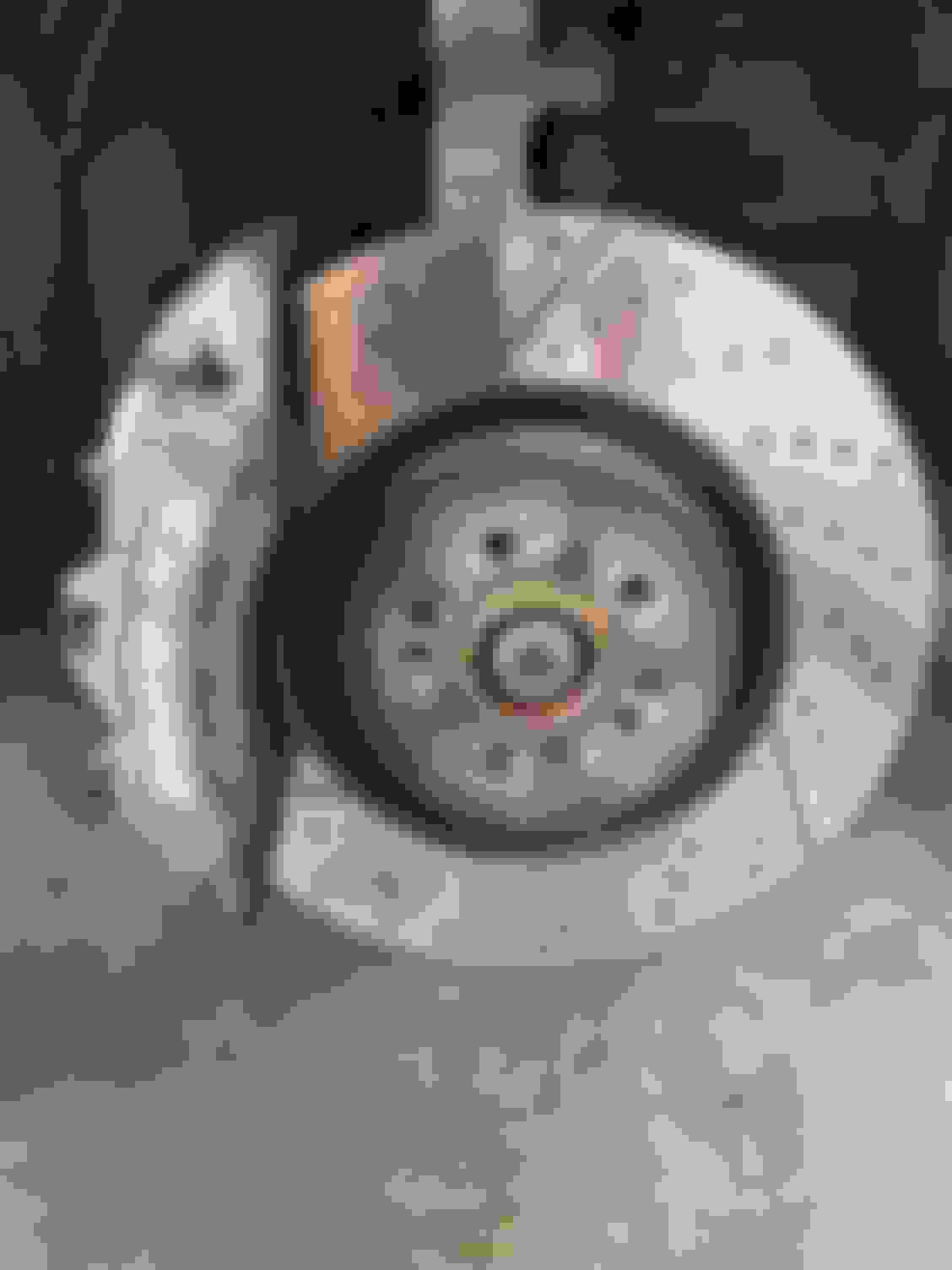
Figure 2: Right front hub, disc rotor, and caliper -- ready for service!
Figure 3: Better view of caliper assembly. Note anti-rattle spring, center bolt/support, retaining pins (2 places), and wear sensor covering brake pads
DISASSEMBLY INSTRUCTIONS
4. Remove brake pad wear sensor (RIGHT SIDE ONLY) a. Disconnect wear sensor connector body by pulling it outboard from the sensor receptacle. Use needle-nose pliers to grasp the connector body if your fingers don’t fit in the tight space.
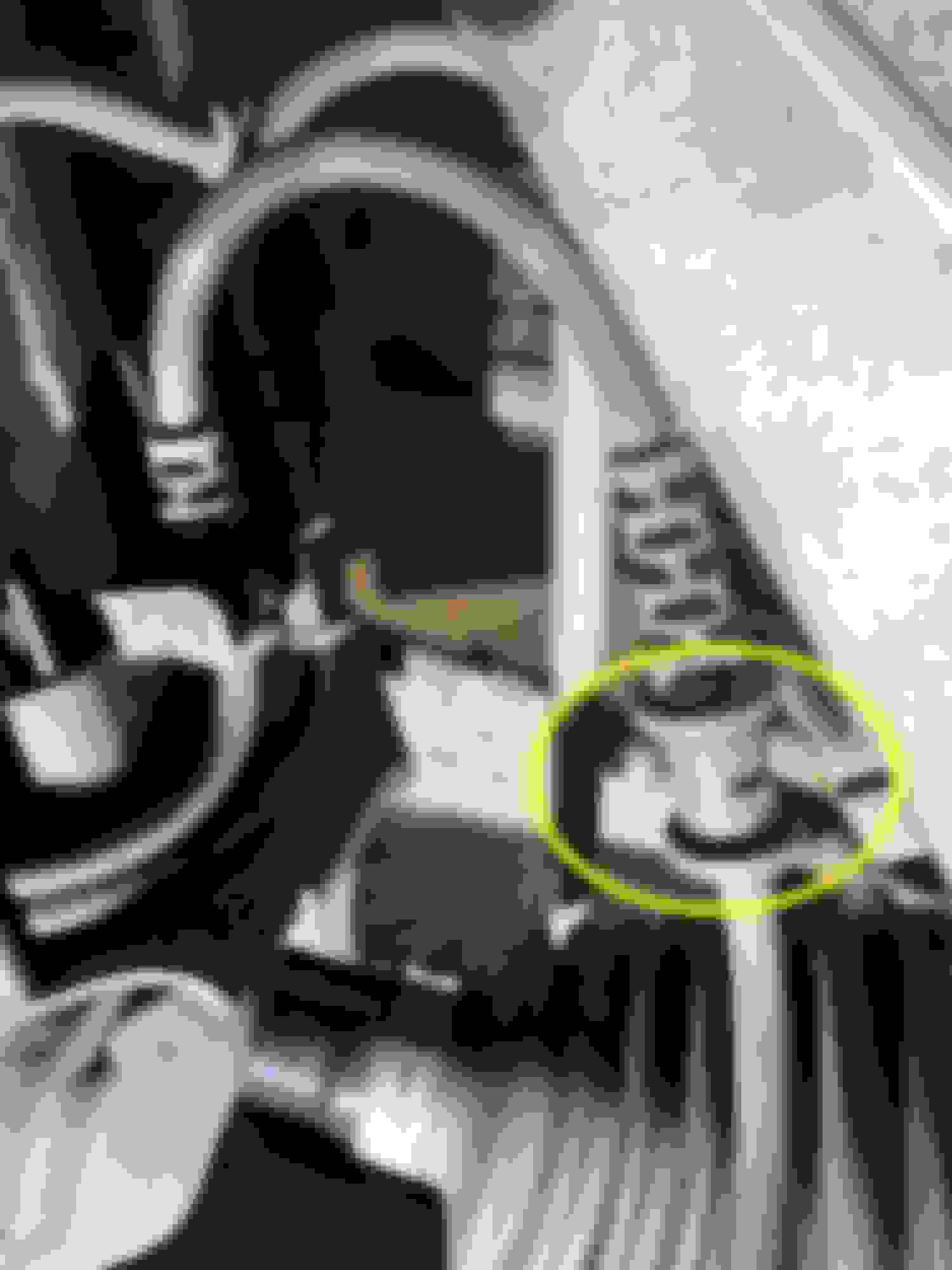
b. Unclip brake wear sensor wire from keeper tab on anti-rattle spring. c. Disconnect wear sensor receptacle wire from wire restraints on front suspension in two places (see photos below). Trace upstream from the connector body -- you'll see the two restraints for the wire that can be popped out with finger pressure only, no tools required. This provides more slack in the wire to allow the caliper body to be moved and bungeed out of the way. (You'll do something similar for the hydraulic brake line in another step below.)
Figure 4: Restraint #1 for brake wear sensor wire -- pops out of clip with finger pressure Figure 5: Restraint #2 for brake wear sensor wire -- pops out of clip with finger pressure
5. Remove brake pads (BOTH SIDES)
b. Using 13mm socket, loosen (but don't completely remove) bolt from center support under anti-rattle spring. Tap gently with metal-faced hammer on bolt head to drive center support out for removal.
c. Using drift pin punch, drive lower retaining pin inboard and then with pliers pull retaining pin out from anti-rattle spring and caliper body. Repeat for upper retaining pin.
Figure 6: Partially disassembled caliper assembly. Wear sensor disconnected, center bolt loosened, and retaining pins partially punched out.
d. Once the anti-rattle spring and associated hardware are removed, you'll have easy access to pull out the brake pads. A small screwdriver can help pry the pads out to get them started.
Figure 7: Brake caliper assembly after brake pads are removed. Note the three pistons that will be pressed back into caliper body in a later step.
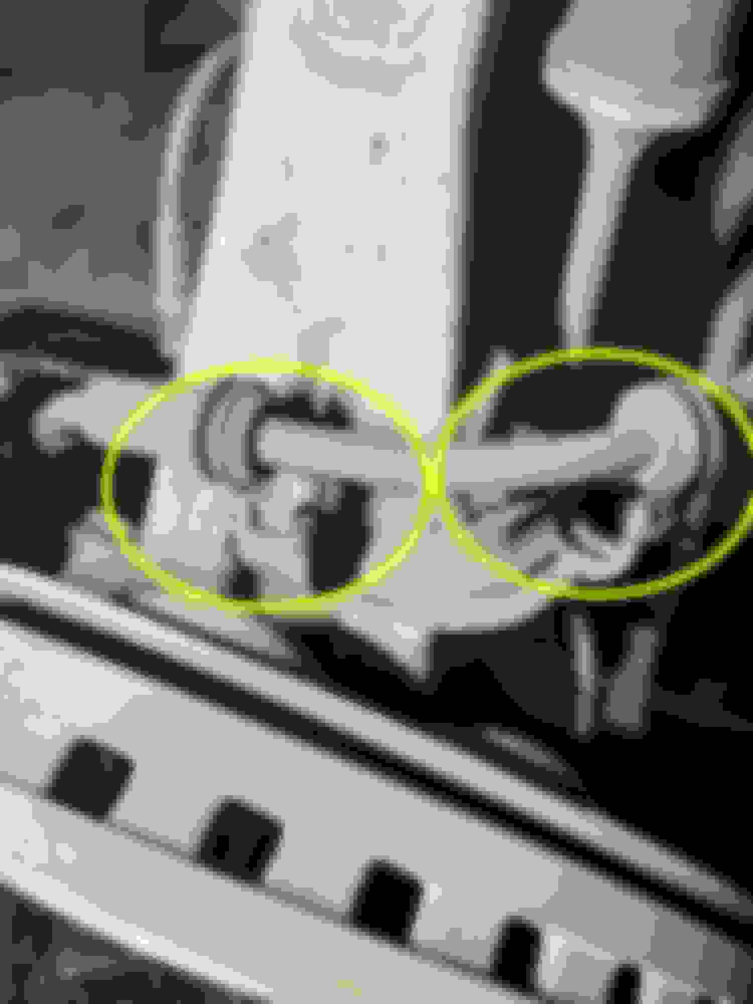
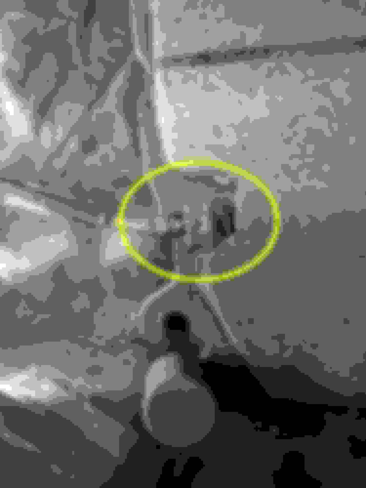
6. Remove brake caliper body (BOTH SIDES) a. Disconnect hydraulic brake line from restraints on front suspension in two places (see photo below). The two clips are a little bit finicky to open. Use a small screwdriver to push upward against the arrow-head tip of the clip, and that should drive the arrow-head back through the hole and allow the clip to open.
Figure 8: Restraints (two places) for hydraulic brake line -- use small screwdriver to push retaining clip open
b. Here I diverge from the M-B WIS instructions. The WIS instructions would have you remove the two 21mm hex M14 bolts that connect the caliper mounting bracket to the steering knuckle. Instead, I prefer to remove the 10mm socket head M12 cap screws that connect the caliper body to the caliper mounting bracket. In either case, loosen the upper bolt but don't remove it, then loosen and remove the lower bolt, then go back and remove the upper bolt while you support the caliper body in one hand. c. Using a short bungee cord or wire hanger, tie off the caliper body so that it doesn’t hang from the hydraulic brake line (and/or brake wear sensor receptacle wire on right side).
Figure 9: Caliper body bungeed out of the way. Note hydraulic brake line with nice amount of slack. The same is true for brake wear sensor wire (hidden).
d. Press brake pistons (three places) into caliper body using piston spreader tool. Pistons should retract almost flush with the caliper body.
7. Remove brake rotor (BOTH SIDES) a. Using a T30 bit, remove the brake rotor set screw. b. Remove the brake rotor from the wheel hub. (Note: It is likely that the rotor hat will be stuck on the wheel hub, requiring some serious hammering on the disc with the dead blow hammer in order to free the rotor from the hub. This problem will be worse in wet or cold environments if rust/salt is able to build up. I really hate hammering on the disc, as I think it cannot be good for the wheel bearings. If anyone knows of a gentler way to lever the rotor off of the wheel hub, please let me know.) c. Clean up any accumulated rust or salt buildup from the wheel hub using a stiff wire-bristle brush. A toothbrush-style brush works fine, but a brush mounted on a drill or angle grinder turns this chore into a fun task. Don’t forget eye protection.
REASSEMBLY INSTRUCTIONS
Note: Generally speaking, reassembly is the inverse of assembly, so I’ll not repeat those instructions in such high level of detail. I will call out torque values and any aspects that are unique to reassembly.
8. Install brake rotor (BOTH SIDES) a. Place the brake rotor (A-166-421-05-12 (or Brembo 09.B805.11 or Zimmermann Coat Z 400 3698 20)) on the wheel hub, being careful to align the set screw hole on the rotor with the threaded hole in the wheel hub. b. Install the brake rotor set screw (A-220-421-01-71 (or Febi-Bilstein 21663)) using a T30 bit, torque to 10 Nm. (Note: I don’t think this torque setting is important. All the set screw does is hold the rotor on the wheel hub until the wheel is installed. Instead, I use the famous TFAR (That Feels About Right) method to install this screw without bothering with a torque wrench. Be careful that you don’t cross-thread or strip the threads in the wheel hub.)
9. Install brake caliper body and brake pads (BOTH SIDES) a. Remove the brake caliper body from bungee cord or wire hangar support.
b. If you go with my recommended workflow, install the caliper body to the caliper support bracket using the A-003-990-79-05 caliper body socket head cap bolts (two places) using a 10mm hex driver. Note: the through-hole clearances in the caliper body are very tight, so install the upper bolt but don't tighten it, then install and tighten the lower bolt, then go back and tighten the upper bolt. Bolt torque is 110 N-m.
If, instead, you chose to go with the WIS-suggested workflow, install the caliper support bracket to the front suspension steering knuckle using the A-019-990-56-01 caliper support bracket bolts (two places) using a 21mm socket, torque to 80 N-m then 45° angular throw.
c. Reinstall the hydraulic brake line in its restraint clips on the front suspension (two places). d. Install new brake pads (A-008-420-20-20 (or EBC Redstuff DP31939C)). Note that the pad with the receptacle for the wear sensor goes on the outboard (I.e., non-caliper piston) side. Some wiggling may be required if the pads are thick or the caliper piston hasn’t been retracted all the way into the caliper body. (Note: I know that most brake pad installations recommend the use of anti-squeal paste on the pad ears and backing plate. The M-B work instructions AR42.10-P-1610CMG specifically say not to use brake paste or lubricants. Before I acquired the vehicle, several brake services had been performed at a M-B dealership, and I found no evidence of any paste or lubricant ever being used on these surfaces. Therefore, I don’t use any paste or lube in this procedure.)
10. Install brake pad retaining hardware (BOTH SIDES)
a. Install the center support and then screw in the 13mm hex center bolt. Torque the bolt to 30 N-m.
b. Lay the anti-rattle spring in place (clip for wear sensor goes toward top), and install the lower retaining pin. Drive the pin into place (gently) with a metal-faced hammer.
c. While holding appropriate pressure to align the anti-rattle spring, install the upper retaining pin. Drive the pin into place (gently) with a metal-faced hammer.
11. Install brake wear sensor (RIGHT SIDE ONLY) a. Reinstall the brake wear sensor wire in its restraints on the front suspension (two places).
b. Insert the brake wear sensor (A-171-540-06-17 (or Bowa A098023)) into the outboard brake pad. Ensure that the little "nub" on the sensor body is pointing inboard, toward the brake rotor. This is essential to proper operation of the wear sensor. See Figures 10 and 11 below.
Figure 10: The nub on the brake wear sensor must point inboard toward the brake rotor. Sensor gets installed on outboard brake pad, nub pointing inboard. Got it? Goooood.
c. Insert the brake wear sensor connector into the receptacle. It should bottom out with a slight click. Refer to Figure 11 to see how the installed connector looks when it’s bottomed out correctly.
Figure 11: Humpty Dumpty, all together again. Note installed positions of brake pads, center bolt/support, anti-rattle spring, retainer pins (two places), and brake wear sensor.
13. Reinstall brake fluid reservoir filter ring, refill brake fluid to MAX line on brake fluid reservoir, reinstall brake fluid reservoir cap, reinstall plastic cover over left suspension shock tower, close hood.
14. Retrieve key, enter driver’s seat while keeping foot off brake, close driver’s door, key to position 1, follow instructions on multifunction display to exit from brake pad assembly position.
15. Test drive the vehicle, and perform any pad bedding-in procedure per recommendation of the brake pad manufacturer.
16. Once the vehicle is parked, crack open a cold beverage -- secure in the knowledge that you’ve gained experience about how your vehicle works and you’ve also saved a bundle in labor charges and often-inflated parts prices!
I would greatly appreciate corrections or suggestions to improve this article. Regards, Joe
Nice write up. Super easy to do. The only issues I had was a stuck rotor and a stripped rotor screw that had to be drilled out. The rears are even easier. Just make sure you lubricate those sliding pins well for the rear rotors. Also, for the front and rear, make sure to liberally coat the back of the rotor where it mounts to the hub with anti-seize otherwise you can have a stuck rotor like I had.
Nice write up. Super easy to do. The only issues I had was a stuck rotor and a stripped rotor screw that had to be drilled out. The rears are even easier. Just make sure you lubricate those sliding pins well for the rear rotors. Also, for the front and rear, make sure to liberally coat the back of the rotor where it mounts to the hub with anti-seize otherwise you can have a stuck rotor like I had.
Thanks, @BlownV8 I can only imagine the frustration with your stuck rotor. What a nightmare! I've had a couple of sessions of hammering away repeatedly on the rotor and seeing no discernible progress. But then I come back a time or two later, and the rotor eventually pops off. It troubles me to abuse the wheel bearings in this way.
I always check the rear caliper pins for smooth action and am now at 80k miles without feeling the need to lubricate them. I'm in Southern California where it's usually very dry. I don't know if this is better or worse than a wet or humid environment.
The WIS (AR42.10-P-0220GZ) recommended lubricant for coating the back of the rotor hub is: A-000-989-76-51 Paste, hot lubrication 1kg. DBL 6879.20. US$65.00 for a tub!!!
A while back a friend who I kinda knew had beat the bloody hell out of the rotors on an E350...dented, cracked and on and on and on....he did not take out the set screw
That is why I plan that any time I replace pads, I am ready to replace rotors....thank god for FCP, eh!
A while back a friend who I kinda knew had beat the bloody hell out of the rotors on an E350...dented, cracked and on and on and on....he did not take out the set screw
That is why I plan that any time I replace pads, I am ready to replace rotors....thank god for FCP, eh!
@OldManAndHisCar , yes, I'm also a member of the forgot-to-take-out-the-set-screw club. When I finally noticed and removed the screw, the rotor fell right off! I'm amazed that the little T30 screw doesn't break off at the head or strip the threads in the rotor.
Re: replacing rotors -- I do it every time I replace pads. Once the vehicle is jacked up and prepared for pad service, it's a fairly small delta to replace the rotors at the same time. (Assuming you can get them to come off!) Some others do a rotor replacement every other time they replace pads. WIS allows only 2mm reduction in rotor thickness before replacement, which isn't very much.
BTW, pad replacement on the front Brembos is so easy -- they were designed for quick pad replacement. Less so on the rear TRW design. I read somewhere that the Brembos were designed so that the gentleman (or gentlewoman) racer could drive their vehicle to the track, pop in track-specific pads, race, then replace with street pads and drive home. Possibly an apocryphal story, but it does reinforce the simplicity of pad replacement on the Brembos.
@OldManAndHisCar ,
BTW, pad replacement on the front Brembos is so easy -- they were designed for quick pad replacement. Less so on the rear TRW design. I read somewhere that the Brembos were designed so that the gentleman (or gentlewoman) racer could drive their vehicle to the track, pop in track-specific pads, race, then replace with street pads and drive home. Possibly an apocryphal story, but it does reinforce the simplicity of pad replacement on the Brembos.
Have done that on Brembo's - track only pads. Slide in yellows at the track...and listen to them squeal........good for Road America and some other fun places.
Have done that on Brembo's - track only pads. Slide in yellows at the track...and listen to them squeal........good for Road America and some other fun places.
Speaking of yellows...I have a set of new-in-box EBC Yellowstuff pads for the rear (DP42137R) that I will likely never use. (I'm happy with the Redstuff DP32137C pads for my application.) If anyone is interested, please make me a reasonable offer and don't forget to account for shipping.
Last edited by joecparrish; 08-07-2024 at 01:18 PM.

 08-06-2024, 07:27 PM