
Understanding Intercooling, Charge-Coolers, Heat Exchangers and Circulation Pumps

 03-11-2013, 07:19 PM
#1
MBWorld Fanatic!
Thread Starter

Understanding Intercooling, Charge-Coolers, Heat Exchangers and Circulation Pumps
I’ve been thinking about intercoolers, done some research on specs, and noticed an interesting trend.
Heat exchangers in one form or another are a pretty mature technology, and car radiators, air-con condensers, oil coolers and heater rads have settled into an established pattern. Medium European cars tend to have horizontal-flow alloy rads with plastic end-tanks, and the cores measure around 600 x 400 x 26, 32 or 40mm thick, depending on engine size (ie: around 6 to 9 litres volume). Heater rads are about Ľ the size of the engine rads, and condensers are almost invariably 16mm thick these days.
However, intercoolers have evolved a lot over the last few years. Diesel turbos with air-air intercoolers are very common, and there’s a lot of information available from on-line sellers of after-market intercoolers. There’s not so much information for current models, or large engines, or charge coolers, but I was still able to do a useful survey of typical intercooler specifications. There’s a clear trend for IC’s to get bigger. They started off quite small, oil cooler size, but have now reached much the same size as the engine radiator.
Modern turbo-charged engines will typically have a 30mm thick intercooler and 30mm radiator, with a 16mm condenser sandwiched in between, and they will all have much the same width and height. Here’s a summary of some common stock coolers, with some truck & tuning units thrown for comparison. The core dimensions are in mm and the volume in cc, which I think gives a reasonable measure for comparison:
CXRacing HE 002: 24x8x2.5” = 610x203x64 = 7,863
Frozen Boost HE 101: 24x7x3.5” = 610x178x89 = 9,663
ZZ Performance Stealth HE: 660x349x44 = 10,215
THS Up-rated VAG 2.0 TFSI IC: 610x415x57 = 14,430
Silicone Intakes IC Type 2: 610x300x101 = 18,469
1991 VW Golf 1.9 TDi: 175x145x100 = 2,538
1995 VW Sharan 1.9TDi: 500x70x88 = 3,080
1998 Mercedes S320CDI: 530x115x65 = 3,962
2001 BMW E46 318d: 540x130x50 = 3,510
2002 Mercedes S600 TT: 580x265x21 = 3,228
2004 Mercedes S65 TT: 580x465x21 = 5,700 (estimate)
2004 Renault Laguna DCI: 530x390x32 = 6,614
2004 Toyota Avensis 2.0D: 642x418x26 = 6,977
2005 Nissan Pathfinder 2.5 TDI: 445x188x65 = 5,438
2005 Seat Alhambra 2.0 TDI: 633x412x25 = 6,520
2005 Opel/Saab All 2.0 turbo: 647x400x29 = 7,505
2008 VW/Seat All 2.0TDI: 617x404x32 = 8,687
2001 All Volvo Turbos: 688x421x30 = 8,689
1993 Volvo FH D12 Truck 340hp: 885x752x63 = 41,928
Granted, a water cooler is more efficient than an air cooler, as the water tubes can be much thinner than air tubes. I think there are two benefits – more cooling fin area for a given volume, plus more ambient air flow due to the reduced obstruction. Therefore I guess that a charge cooler HE needs to be about half the size of an air-air cooler for the same efficiency. That sounds about right, as the charge cooler and the heat exchanger are effectively “two halves” of the intercooler – the water circuit just providing the thermal interface between the two.
IIRC, the V12TT charge coolers have a combined volume of around 500 cu-in, or about 8 litres, which I think is quite reasonable. Having looked at a lot of after-market charge cooler kits (CXRacing etc) it seems that the charge cooler and HE volumes should ideally be similar. That seems to be consistent with the way air-air coolers are designed, with about the same volume dedicated to the internal and external cooling volumes.
Another very rough rule of thumb seems to be that the CC and HE volumes should each equal the engine capacity itself – and double it for high-boost engines (double-digit PSI – that sort of level). That’s not a rule that’s written down anywhere, it’s just my observation. I think its fair, given that the more recent examples above have typically four times the engine capacity – equivalent to twice the capacity for water cooling.
Whichever way you look at it, all this illustrates how relatively small the S600/CL600/SL600 heat exchanger is. It’s only 3.2 litres, and really ought to be twice that – similar to the charge coolers (and most cars engine radiators). And there’s an argument for saying it should be four times greater. The dimensions above came from radiator distributor web-sites, and they allow easy comparison of radiator and intercooler specs. For modern cars and trucks (which have used intercooled turbos for a long time, and are well-developed) it’s now normal for the intercooler to be the same size as the radiator – and even slightly bigger in some cases. The S600 radiator is 641x469x40mm or 12 litres, which sounds like a good target. The bottom line seems to be – the bigger the better.
Nick
 03-13-2013, 06:14 PM
#2
MBWorld Fanatic!
Thread Starter
I'm pulling together various posts and charts on pumps and heat exchangers into one thread, and here are a few posts copied from elsewhere. Don't worry if you already saw this, I've got somenthing useful coming up....
I suspect the benefit of a high flow pump is the reduced delay to START cooling the charge coolers - when the pump is first switched on due to high IAT, that is. There's quite a lot of hot water sitting in that system - especially thinking about the pipes that run past the turbos - and it must take time to get that round a full circuit.
The argument that high flow rates result in higher charge temps doesn't work on many different levels. Its probably best consider a cooling circuit interms of how it carries heat energy around, rather than how it behaves from a temperature perspective.
Firstly, if the water doesn't stay in the HE long enough to cool down, then the converse must also apply - the water won't stay in the charge coolers long enough to heat up.
Although the water will pick up less heat in each pass through the IC when it flows fast, it will complete more circuits in a given time, so it will complete more passes.
So the question is whether the faster flow is more than enough to offset the shorter heat transfer time. Heat exhanger behaviour is complex, there's nothing simple or linear about how they work. Heat transfer is governed by many variables, but the simplest one is that heat flow is proportional to temperature difference. Therefore if the coolant is cold, the heat transfer willbe fast.
If the coolant circulates slowly, so that it has time to absorb a lot of heat, its temperature will tend to approach that of the air its cooling. As it does so, the temp differential falls, and rate of heat flow also falls. Therefore the highest heat transfer happens when the coolant is coldest.
That's another way of saying that heat transfer increases as flow rate increases, which is one of the other guiding principles of heat exhangers. That's not linear though, as heat transfer depends on other factors - like the surfaces of the tubes. Rough sufaces and high flow speeds will encourage turbulent flow, which is more effective at heat transfer. There's more convection transfer when there's turbulence, so you don't just rely on the conduction of the coolant.
Turbulent flow is difficult to predict, and depends on the fluids, the surfaces and the Reynold's number. Although I did study aerodynamics and fluid mechanics when I was at British Aerospace, I don't pretend to fully understand it all. However, if there's one thing that DOES encourage turbulence, its high fluid speed. Maybe the Bosch pump is fast enough to cause turbulence, but a faster pump MAY encourage it more, and it certainly won't make it worse.
Water has a high heat capacity, and it could be that the stock pump is fast enough to ensure that the coolant temperature rise through the IC's is low enough during each pass to ensure that the capacity of the coolant itself isn't the bottleneck in the overall cooling system. The limitation may well lie elsewhere, such as with the thermal resistance of the HE to ambient air, or with the IC to the intake air. In that case, the cooing fins may be held at the coolant temperature quite effectively, but there might simply be not enough of them to conduct the heat to what is a fairly insulating medium. But I'm starting to speculate there.
The end result is generally that higher flow rates increase heat transfer, and the END RESULT is that the medium being cooled will be cooler.
Of course it could be that the real benefit is that cooling simply STARTS faster for the first reason I gave. Given that this is effectively a thermostatically-controlled system that only runs on demand, that could be the overriding advantage.
Nick
03-13-2013, 06:15 PM
#3
MBWorld Fanatic!
Thread Starter
This is quite an interesting pump - or rather an interesting pump controller.
http://www.daviescraig.com.au/Contro...0-details.aspx
When we talk about Bosch, Johnson and Meziere pumps, we talk in terms of swapping pumps out and using the same electrical interface.
I suspect that one of the biggest issues with the stock pump is the way its controlled - pump turns on at 47oC IAT; pump turns off at 35oC IAT. Maybe it works better than I give it credit for, but it does seem a rather crude algorithm.
Running at full speed all the time is probably too wasteful, but I think it needs better control, that allows the coolant to be kept cooler all the time. Some sort of variable speed control is probably what's needed, and that's what the Davies Craig controller appears to do. There's a variable duty cycle - 25% at low temperature, 50% at medium, and continuous at high temperature.
Since the controller is targetted at engine cooling systems, there isn't the flexibility to support low-temperature cooling systems like ours. The target temperatures can be set to 75, 80, 85, 90 or 95oC, which is too high for us. However, at the lowest setting, the pump would be run at least 10sec on/30sec off all the time, increasing to 10 on/10 off for any temp over 55oC, and continuous over 70oC.
That low duty cycle would probably be ideal to stop the coolant in the pipes heating up during cruising, when there's no boost. But I'm not sure its enough to keep the temp below 55oC when the engine IS on boost.
Perhaps there's a simple way to add a resistor in series with the thermistor, so the controller thinks the coolant temp is higher than it is.
And thinking out loud for a moment, I'm sure there must be a temp sensor somewhere that the stock system already uses. That should make the installation a bit easier. I guess its only an air sensor though.
I expect the Davies Craig controller is intended to be used with their own electric water pumps, but just to prove a theory, it would be interesting to try the controller with the stock Mercedes pump, and see what that does to IAT and subjective performance. I'd like to use one of their pumps as well, but I'd like to understand the individual contributions from the controller, pump, HE, etc.
03-13-2013, 06:15 PM
#4
MBWorld Fanatic!
Thread Starter
People are always drawing comparisons with water circuits when they try to explain elementary electronics, so a backwards comparison might work as well. The hydraulic pump is like the dynamo or battery, the pipes are the wires, and the IC & HE are the resistors. The pump generates a certain pressure, and this is analogous to voltage.
The whole circuit has an overall resistance to flow, which restricts the current, so to speak. If there was just one IC, the resistance would be higher, as all the flow has to go through one resistor, rather than being split between two parallel units, and so on.
Unless we make changes to the IC or HE, that resistance is fixed, so we can only change the pump. The pump will only achieve its maximum voltage/pressure when it’s delivering no current. That's like putting a voltmeter across a battery - you get the max voltage, but there's no load. As soon as current starts to flow, the voltage drops, and when you take it to the extreme with nothing connected to the pump, you will achieve the maximum flow, but there will no pressure. Similarly, when you crank an engine, the battery voltage plummets. These extreme conditions are just like open circuit and short circuit on a battery - you either get maximum pressure or maximum current, but not both at the same time.
I believe pumps typically operate in a middling condition, where both the pressure and flow are somewhere near half the respective max values. So if a pump can achieve 6 psi open circuit and 10 gpm open circuit, I'd expect it to achieve something like 4 psi at 5 gpm in a typical installation. That's what all those pressure/flow charts are all about - they show how much pressure loss you get when coolant starts to flow - or alternatively how much the flow drops when you add resistance to the circuit – it’s the same thing. Pressure times flow is power, and pumps deliver most power to the fluid when they work in the middle region. If the flow or the pressure is close to the maximum value, the pump is working against too little or too much resistance respectively, and the pump won't be doing as much useful work as it could.
The faster you push the coolant round, the more pressure you need (but its not linear, it’s more like a square function). So, if we fit a bigger pump with a higher flow rate, that MAY increase the flow around the system, but ONLY if the pump can generate a higher pressure at that higher flow rate. What we're looking for is not just a pump with a high max pressure, or with more max flow, but one where the pressure/flow curve moves up and to the right, in the area where the system actually works.
Alternatively, we could fit a larger HE, hopefully one with more pipes, and hence less flow restriction. That in itself will increase the overall flow rate slightly, because the total resistance of the cooling system is reduced. The resistance will reduce, the flow rate will increase, and the pressure will reduce. The operating condition of the pump will find a new equilibrium point, and will move to the right slightly. That's a good thing, because we gain from the reduced thermal resistance of the larger HE, plus the higher flow rate round the cooling circuit.
So we do need to consider both pressure and flow rate, but they are related.
Many electric pumps are designed for engine cooling, so they often have 1.25" outlets. The Meziere and Davies Craig pumps have the option of various diameter outlets, including 19mm, which should be ideal for our cars.
Last edited by Welwynnick; 03-15-2013 at 07:45 PM.
03-13-2013, 06:16 PM
#5
MBWorld Fanatic!
Thread Starter
I think there's no doubt the Davies Craig would be a good pump, but there's a few things that point me towards the Meziere WP136S or Johnson CM90.
Because this is a modification, I think its best to tread in someone else's steps - in other words, use a proven route to achieving what you want. Let other people find out the pitfalls for different potential solutions where you can. Meziere and Johnson aren't totally without their issues, but they're widely used and fairly well understood.
My impression is that the Davies Craig 80 and 115 pumps are intended as replacements for engine pumps. They have high-flow characteristics: shallow pressure/flow curves and large ports. I think the charge cooler circuit isn't like that - its higher resistance and lower flow. There are two, small heat exchangers, and the pipes are small. The EWP80/115 aren't auxilliary pumps, whereas Bosch, Meziere and Johnson are intended as aux pumps. They make other models for engine cooling.
Davies Craig do make a couple of specific auxilliary pumps, the EBP (EBP15) and EBP25 (which looks suspiciously familiar) but they doen't flow very much. However, they do have 3/4" connections
The EWP80 & 115 have large inlets and outlets, which are suited to engine cooling. All the auxilliary pumps have 3/4" connections, which makes life easier for us.
What's really interesting for me about Davies Craig is the pump controller, which gives a us a better option than the Mercedes ECU. I think that might be really worthwhile, and not necessarily with Davies Craig pumps. It could be considered as an independent option to the pump itself - something to add after upgrading the pump, or even to be used with the stock pump, as an effective alternative to changing the pump.
Davies Craig pumps seem to be well-distributed around the World, but I think I would go for a WP136S or CM90, there's no great problem with importing from the US. I've done that with lots of electronics and car parts with no issues.
Last edited by Welwynnick; 03-13-2013 at 07:48 PM.
03-13-2013, 06:16 PM
#6
MBWorld Fanatic!
Thread Starter
I've been trying to put together a comparison of all the popular circulation pumps, but the manufacturers don't use the same data for comparisons. Sometimes we just get a open outlet flow figure, and sometimes its flow against a particualr head of pressure, whcih is more meaningful (but its never the same pressure). Some pumps are designed for engine cooling, which has low restriction. Others are designed for auxilliary circulation like charge cooling, which has less flow, smaller heat exchangers and long, small pipes. These pumps will have high pressure, low flow charcteristics, but its difficult to figure which these are.
To add to the confusion, there are lots of different units in use. Flow can be given in litres/min, litres/hour, gallons/min or gallons/hour (and that's before US vs imperial gallons even gets in the way). Similarly, pressure can be given in PSI, kPa, bar, etc. As well as providing incomplete information, some manufacturers even post the wrong info in their data sheets (one of them can't convert kPA to PSI correctly). So how anyone possibly know whether a Johnson is better than a Bosch when there are so many variables?
I think its important to understand how these pumps are being used - what part of their operating envelope is used in our charge cooler systems? That needs some understanding of the flow resistance of the system, which tells us how much presure is required to achieve a certain flow rate. Unfortunately its not linear (like electrical resistance). Its probably best represented as a second-order polynomial function, which is typical of fluid drag. Car aerodynamic drag increases with the square of the speed, and I think coolant circuits are similar. Davies Craig published a resistance curve for a typical 6-cylinder engine in some of the EWP115 literature, so I've assumed its representative, and modelled it as a simple square-law function with appropriate scaling. I called this Engine Cooling Resistance.
Charge cooling probably has similar characteristics, but with higher resistance, for the reasons given above. I read some very useful posts on MBW that said some typical pumps achieve around 5-6gpm installed flow, and this gives a big clue as to where the flow/pressure curve sits for charge cooler systems. I modelled another square-law curve that fitted a sensible characteristic, and called this Charge Cooling Resistance. Where the pump curve crosses the resistance curve, that's how much flow you'll get in a particular installation. Of course its only a guess, but its based on the best information I can find, and there's not much of it. If anyone can help fill in the missing pieces with actual installed flow or installed pressure, I'd be really grateful.
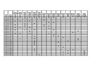
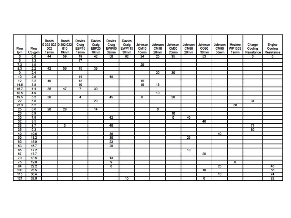
I've recorded all the information I can find on a spreadsheet, and plotted some charts, which I'll post tomorrow (takes lots of file conversions). I consolidated everything into kPa pressure vs litres/min flow (sorry Americans!), but I'll try to plot some dual scales. 1 bar = 14.7psi = 101kPa
The first conclusion from all this is that unrestricted flow data gives littel indication of installed performance. Charge coolers are relatively low flow/high pressure circuits, and a pump's ability to generate a high pressure into a completely blocked outlet is probably a better indication of installed performance (but we never actually get that information from anyone). Back soon
Nick
To add to the confusion, there are lots of different units in use. Flow can be given in litres/min, litres/hour, gallons/min or gallons/hour (and that's before US vs imperial gallons even gets in the way). Similarly, pressure can be given in PSI, kPa, bar, etc. As well as providing incomplete information, some manufacturers even post the wrong info in their data sheets (one of them can't convert kPA to PSI correctly). So how anyone possibly know whether a Johnson is better than a Bosch when there are so many variables?
I think its important to understand how these pumps are being used - what part of their operating envelope is used in our charge cooler systems? That needs some understanding of the flow resistance of the system, which tells us how much presure is required to achieve a certain flow rate. Unfortunately its not linear (like electrical resistance). Its probably best represented as a second-order polynomial function, which is typical of fluid drag. Car aerodynamic drag increases with the square of the speed, and I think coolant circuits are similar. Davies Craig published a resistance curve for a typical 6-cylinder engine in some of the EWP115 literature, so I've assumed its representative, and modelled it as a simple square-law function with appropriate scaling. I called this Engine Cooling Resistance.
Charge cooling probably has similar characteristics, but with higher resistance, for the reasons given above. I read some very useful posts on MBW that said some typical pumps achieve around 5-6gpm installed flow, and this gives a big clue as to where the flow/pressure curve sits for charge cooler systems. I modelled another square-law curve that fitted a sensible characteristic, and called this Charge Cooling Resistance. Where the pump curve crosses the resistance curve, that's how much flow you'll get in a particular installation. Of course its only a guess, but its based on the best information I can find, and there's not much of it. If anyone can help fill in the missing pieces with actual installed flow or installed pressure, I'd be really grateful.
I've recorded all the information I can find on a spreadsheet, and plotted some charts, which I'll post tomorrow (takes lots of file conversions). I consolidated everything into kPa pressure vs litres/min flow (sorry Americans!), but I'll try to plot some dual scales. 1 bar = 14.7psi = 101kPa
The first conclusion from all this is that unrestricted flow data gives littel indication of installed performance. Charge coolers are relatively low flow/high pressure circuits, and a pump's ability to generate a high pressure into a completely blocked outlet is probably a better indication of installed performance (but we never actually get that information from anyone). Back soon
Nick
Last edited by Welwynnick; 03-13-2013 at 07:51 PM.
The following users liked this post:
Jeffrey Miller (12-30-2019)
03-13-2013, 06:17 PM
#7
MBWorld Fanatic!
Thread Starter
My goodness this was hard work.....
The pdf below is MUCH easier to read.
The pdf below is MUCH easier to read.
Last edited by Welwynnick; 03-14-2013 at 06:51 PM.
The following users liked this post:
AMG-Driver (07-12-2016)
Trending Topics
03-14-2013, 07:43 PM
#9
MBWorld Fanatic!
Thread Starter
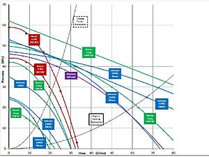
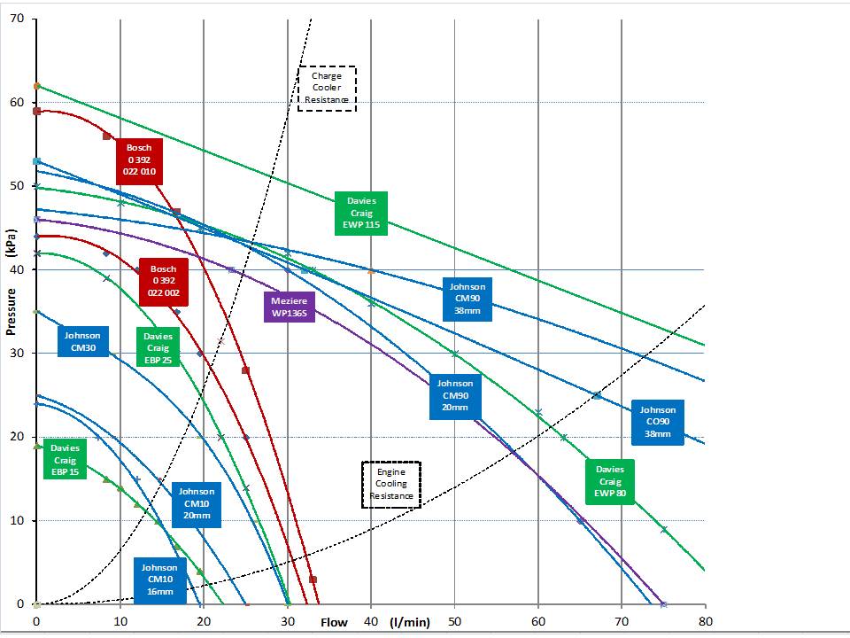
What I've done in the chart is to plot all the data points on the spreadsheet. The data comes from manufacturer websites and data sheets, and very little of it is directly comparable. Fortunately, circulation pumps tend to have simple characteristics, so I plotted what points I had available and ran polynomial interpolations to give a good fit. Most curves were simply second-order, but a few are slightly better with third-order. The graph shows the pumps' data points, but the curves are all interpolations
I also plotted two square-law cooling circuit resistance curves. These are characteristics of the load that the pump sees, and the point where the pump and resistance curves cross gives you the installed flow. The engine cooling resistance comes from Davies Craig data sheets, and is probably reasonable. The charge cooler resistance is based on what installed flow and pressure data I could find on-line, mostly on MBWorld. Its a guess, but I think its representative.
Of course, the charge cooler resistance is much higher than the engine, so an electric pump that's suitable for engine cooling is unlikely to be good for charge cooling, and vice-versa. I think the M275 charge cooler operates in the 20lpm / 30kPa region, so that's the installed pressure and flow that candidate pumps have to meet simultaneously. Its no good being able to dump 20l/min into a bucket, for example....
Most pumps have good data of some sort, but I have to admit I've come up short on Meziere WP136S data. The manufacturer only gives the open outlet flow, so I've guessed that its performance will be similar to the Johnson CM90 with the 20mm outlet. So there's a big health warning there, and if anyone knows any better, please say so.
Aside from that, I think we now have a good way to make fair comparisons between different pumps, and understand what's likely to work in a charge cooler circuit. Some of teh conclusions are:
1) Since a few of the pumps have optional porit sizes (CM10, CM90, EWP80) its interesting to see how that affects performance. Obviously the larger outlets flow more into low resistance, but once they're in a charge cooler system, outlet size makes little difference.
2) The difference between the old and new Bosch pumps is clear, they're both good with high-resistance loads, and you can see how much better the 0 392 022 010 is.
3) Davies Craig have the widest range, from the tiny EBP15 (actually a Bosch pump) up to the EWP115, which is top dog. Although that's designed for engine cooling, it still seems to have the highest static pressure of all, and it's still not that big or expensive.
4) I think the most interesting result though, is where the CM30 fits in. Although its small, cheap, light, and has low power consumption, there really aren't any performance reasons to chose it over even the old Bosch 0 392 022 002, let alone the Meziere.
5) The other thing that occurs to me is that the resistance curve is rather steep, so a bigger pump will only give a small improvement in flow over stock.
We may get more flow improvement from reduced cooling system resistance, than from a bigger pump. Its difficult to do anything about the charge coolers themselves (though they're a good size) so the scope for improvement lies with the heat exchanger. I'm thinking in terms of using a largerHE, or a second HE in parallel with the stock one. As well as the reduced thermal resistance, that would almost certainly improve the total system flow as well.
Indeed, the current drawn by each pump over their operating flow range (where given by the manufacturer) often increases with reducing resistance, indicating that the pump is drawing and delivering more power. If you imagine the resistance curve moving slightly to the right, towards the engine resistance curve, the crossing point will move down to a point with lower pressure and higher flow. High pressure in itself isn't what we need for cooling - its the mass flow rate, and a low resistance circuit gives us more flow for free.
There, that's what I've been meaning to get to the bottom of for a long time. Hope you find it useful.
Nick
Last edited by Welwynnick; 03-15-2013 at 12:03 PM.
The following users liked this post:
2007 SL600 (01-10-2020)
 03-15-2013, 05:20 PM
#11
MBWorld Fanatic!
Thread Starter
There are two other things I wanted to understand, and I'm not really there yet.
The first is just how much the water circuit itself restricts the performance of the charge cooling system. It could be that charge coolers are like water cooled PCs. The gaming boys really want to keep their over-clocked CPU temps down, just we want to keep our over-boosted IATs down. Water has such high heat-carrying capacity, that a bigger pump or large bore pipes make very little difference to the processor temperature. The PC cooling bottleneck remains at the interface to the air - the heat exchanger.
Well, we know that water has high heat capacity - more than 4 times higher than air, by mass. It also has high heat conductivity - about 20 times higher. But those figures don't take into account that water has higher density - nearly 1000 times higher. Combine them together, and water's cooling capacity, volume for volume, is nearly 100,000 times greater than air.
When you look inside radiators and heat exchangers, the water passages naturally have much smaller x-sectional area than the air passages. I couldn't find much information about this, but I guess the water passages are about ten times smaller than the air. Even when you consider the extra area of the cooling fins on the air side, I'm sure that water has far more capacity. So could it be that a bigger pump on the V12TT makes little difference, aside from getting the coolant circulating faster, once it's switched on.
I think its clear that a better pump will circulate the water faster - though perhaps not very much faster. But I don't know whether it already goes fast enough?
Nick
03-15-2013, 07:04 PM
#12
MBWorld Fanatic!
Thread Starter
The second thing I'd like to understand is the heat exchanger's influence on the cooling circuit resistance. I think typical charge cooler circuits are relatively low-flow/high resistance circuits, but I'm not sure where the resistance comes from. My guess is its the heat exchanger, and this is why. From air-air intercooler design, it seems that the optimum design is where the compressed air and ambient air channels have similar total volume within the intercooler. This suggests to me that an HE should have a similar volume to the charge cooler (the IC and the HE being two halves of a virtual intercooler - just separated by a circulating water interface).
In the case of the V12TT, the HE is rather smaller. Its also a different shape. If you consider the water flow through those narrow-section tubes, its a pretty slim HE, with relatively few tubes, and rather long ones at that. I think water flow through the charge coolers is rather easier; they're short, fat and deep by comparison,and they're connected in parallel. So conceptually, I imagine the two IC's as being stacked one on top of the other, air flowing one way, and water flowing orthogonally to that. If you stack them together their combined shape is close to being a cube.
When I think of the resistance to water flow, I think of the parallel with electricity. If you want to make a high resistance wire, you make it long and thin. If you want to make it low resistance, you reduce the length, and increase the width and height. In less hand-waving terms, resistance = (resistivity x length) / (cross-section area). Does that analogy hold true with water flowing through a heat exchanger?
Well, when you look inside the IC's, they seem have much the same configuration as a radiator. The water channels still have around 10% of the size of the air channels, and I think that's a bit like saying the IC and the HE have similar "water resistivity". There you might be able to get a measure of the relative water flow resistance by comparing the dimensions, which from memory are as follows:
IC: LxWxH = 20x20x17.5cm (height is two units stacked)
HE: LxWxH = 58x2.1x26.5cm
So what is the relative water resistance (arbitrarily assuming for comparison purposes that "water resistivity" for both is unity)?
IC: L/(WxH) = 20/(20x17.5) = 0.057 water resistance units
HE: L/(WxH) = 58/(2.1x26.5) = 1.04 water resistance units
Total cooling resistance = 1.10 water resistance units
So just going by their shape and dimensions, the HE would have around 18 times as much water flow resistance as the charge coolers, with much of that simply being down to the smaller number of water tubes running across the exchanger. Of course it won't be as simple as that, as some of the total resistance will come from the inlets and outlets to the tubes, but even its half that difference in reality, the HE may still have an order of magnitude more flow resistance than the IC's. And I guess that would probably dominate the behaviour of the cooling circuit - if we want to increase flow, reducing resistance is probably a good way to do it, and the HE is probably the best place to start.
Remember I said in the first post that the HE ought to be at least as large as the IC? Well, consider the big CX Racing HE, which has similar volme to the IC's. What would the water resistance of that be?
CXRacing HE 002: 24x8x2.5” = 61x20.3x6.4cm = 7,863cc
Water resistance = 61/(6.4x20.3) = 0.469 water resistance units
Total cooling resistance = 0.526 water resistance units
The CX HE has more than twice the core volume, and less than half the resistance, of the stock cooler. And the combined IC + HE resistance is also more than halved. It stands to reason, as larger HE's usually gain volume from height and width (their cross-section area, in fact). In other words, since the length is usually fixed around 24 inches, the core colume and the flow resistance will both improve in direct proportion to the cross-sectional area. To take an extreme example, if we used an S600 engine radiator (12 litres) as the HE, that would might have four times the volume and one quarter the resistance of the stock HE (and still not as low as the IC's).
I think that illustrates that the HE is the major bottle-neck in charge-cooling flow (as well as in the overall heat capacity) so there are double gains to be had in improving the HE. Flow would be significantly greater even with the stock pump, and with the IC resistance curve moving right towards to the engine resistance curve, there's a lot of scope for a bigger pump.
Nick
03-16-2013, 07:49 PM
#13
MBWorld Fanatic!
Thread Starter
I think CXR make three types, the largest being 24 x 8 x 2.5" core. Similar size to the Frozen Boost cooler. I'd like to know if they fit, but I'm not sure. I did have my front bumper off a couple of months ago, but I was takling ABC problems, and didn't heve time to experiment with HE's. I'm not sure if the best place is under the bumper bar or behind it. Mounting beneath it, there seems little room to fit in the engine oil cooler. Going behind, its squeezed by the air con condenser. Whever you go, you gotta consider physical interference with inlet & outlet, headlamps, and don't forget the bonnet catch!
The thing that I really shouldn't be dreaming about is fitting a second radiator in there somewhere. Why mess around with small HE's when there are so many proper ones about? I like the idea of a full height HE, so ALL the air goes through the HE, AC and rad. That's how most modern turbos are configured. They don't have to be thick to have a large core volume, and don't forget that many rads have tranny coolers built-in. Why not run the ABC coolant through that? The steering oil goes through the AC. That would all make for a tidy front end. Of course I'm having difficulty finding a decent size rad that would fit in there.....
Nick
Last edited by Welwynnick; 03-16-2013 at 07:51 PM.
03-16-2013, 08:51 PM
#14
Junior Member
Join Date: Jan 2013
Posts: 60
Likes: 0
Received 1 Like
on
1 Post
'06 S65 AMG W220 12.31@119_MPH (Stock)
Thanks. What did you have in mind? Are you looking to keep the stock cooler and add another? Have you tried fitting anything, or just taken some dimensions? Have you taken the bumper off? That's not difficult once you've got the wheel arch liners off (and first disconnected the parking sensors loom!) For a big car, there's not a lot of space in there. Is your car the W220 or W221?
I think CXR make three types, the largest being 24 x 8 x 2.5" core. Similar size to the Frozen Boost cooler. I'd like to know if they fit, but I'm not sure. I did have my front bumper off a couple of months ago, but I was takling ABC problems, and didn't heve time to experiment with HE's. I'm not sure if the best place is under the bumper bar or behind it. Mounting beneath it, there seems little room to fit in the engine oil cooler. Going behind, its squeezed by the air con condenser. Whever you go, you gotta consider physical interference with inlet & outlet, headlamps, and don't forget the bonnet catch!
The thing that I really shouldn't be dreaming about is fitting a second radiator in there somewhere. Why mess around with small HE's when there are so many proper ones about? I like the idea of a full height HE, so ALL the air goes through the HE, AC and rad. That's how most modern turbos are configured. They don't have to be thick to have a large core volume, and don't forget that many rads have tranny coolers built-in. Why not run the ABC coolant through that? The steering oil goes through the AC. That would all make for a tidy front end. Of course I'm having difficulty finding a decent size rad that would fit in there.....
Nick
Cheers
03-23-2013, 02:11 PM
#16
MBWorld Fanatic!
Thread Starter
However, intercoolers have evolved a lot over the last few years. Diesel turbos with air-air intercoolers are very common, and there’s a lot of information available from on-line sellers of after-market intercoolers. There’s not so much information for current models, or large engines, or charge coolers, but I was still able to do a useful survey of typical intercooler specifications. There’s a clear trend for IC’s to get bigger. They started off quite small, oil cooler size, but have now reached much the same size as the engine radiator.
Modern turbo-charged engines will typically have a 30mm thick intercooler and 30mm radiator, with a 16mm condenser sandwiched in between, and they will all have much the same width and height.
Modern turbo-charged engines will typically have a 30mm thick intercooler and 30mm radiator, with a 16mm condenser sandwiched in between, and they will all have much the same width and height.
Recent cars that were designed around turbo engines almost invariably have the condensor at the front, and the intercooler sandwiched in between. I guess the condenser doesn't like the heat from the intake cooler. Heat exchangers are usually arranged hot-to-hot and cold-to-cold, so if the rad runs hotter than the HE runs hotter than the AC, then that's the logical sequence. It seems to have become the rule these days, apart from some Fords, BMWs and Mercs that still have deep, low-profile HE's mounted low down and at the front, where they don't obscure the condenser.
Which opens up some interesting options... If its possible to move the S600 condenser forwards a few cm (might not be feasible) then there are some advantages in sandwiching a large HE in the middle. Although the condenser sits snuggly between the rad's end tanks, there are four AC & PAS pipes that are squeezed in front of the rad, and they make it difficult to put a large HE at the front. If the condenser can go at the front, that helps fitting the HE.
All the current units - Rad, AC & HE - are all cross-flow, but a down-flow HE with tanks at top & bottom, with the AC nested in-between, might be a good packaging solution. I'm not sure what that solution might be; packaging is definitely a problem. The HE outlets must still be able to get past the condenser, and that rules out several options, including all the purpose designed HE's that I've ever seen. Its not a problem that new cars have.
Nick
03-24-2013, 11:24 AM
#17
MBWorld Fanatic!
Thread Starter
I think CXR make three types, the largest being 24 x 8 x 2.5" core. Similar size to the Frozen Boost cooler. I'd like to know if they fit, but I'm not sure. I did have my front bumper off a couple of months ago, but I was takling ABC problems, and didn't heve time to experiment with HE's. I'm not sure if the best place is under the bumper bar or behind it. Mounting beneath it, there seems little room to fit in the engine oil cooler. Going behind, its squeezed by the air con condenser.
Realistically, there probably wouldn't be room beneath the bumper and above the engine oil cooler anyway.
I think it would have to behind the bumper beam, and if it does't fit there, I'm not sure what would - it would have to be something smaller.
CXR do a smaller HE that measures 21 x 6 x 2", and that doesn't have a filler, so it might fit under the bumper. It is rather smaller though - 4130cc vs 7866 cc, and its a dual pass HE with inlet and outlet at the same end (not what we want).
Nick
03-24-2013, 05:32 PM
#18
MBWorld Fanatic!
Thread Starter
<FONT style="BACKGROUND-COLOR: #f5f5ff">
<SPAN style="FONT-FAMILY: Arial; COLOR: black; FONT-SIZE: 9pt">Late Model Racecraft 2012+ ZL1 Camaro Upgraded Heat Exchanger
Core: 616 x 413 x 50mm = 12,720 cc
Overall: 667 x 420 x 57mm
Cross-flow, Large HE, but length & thickness may be too high
<SPAN style="FONT-FAMILY: Arial; COLOR: black; FONT-SIZE: 9pt">Late Model Racecraft 2012+ ZL1 Camaro Upgraded Heat Exchanger
Core: 616 x 413 x 50mm = 12,720 cc
Overall: 667 x 420 x 57mm
Cross-flow, Large HE, but length & thickness may be too high
Last edited by Welwynnick; 03-26-2013 at 05:55 PM.
03-29-2013, 11:56 AM
#19
MBWorld Fanatic!
Thread Starter
Sorry about that last post, I tried to update it several times but couldn't edit it for some reason.
Here's a quick list of various heat exchangers with comments, plus comparisons with the stock S600 units:
Here's a quick list of various heat exchangers with comments, plus comparisons with the stock S600 units:
Late Model Racecraft 2012+ ZL1 Camaro Upgraded Heat Exchanger
Core: 616 x 413 = 2544 cm2 x 50mm = 12,720 cc
Overall: 667 x 420 x 57mm
Cross-flow, Large HE, but length & thickness may be too high
ZZP Stealth Heat Exchanger
Core26x13.75x1.75" = 660 x 349 = 2303 cm2 x 44 mm = 10,252 cc
Overall 26.5x17x2"= 673 x 432 x 51 mm
Bottom inlet& outlet; large capacity, but pipes need mod
Frozen Boost HE Type 101
Core: 610 x 178 = 1085 cm2 x 89 mm = 9,636 cc
Overall: 660 x 178 x 89 mm
Cross-flow, Dual Pass,˝” NPT connections
CX Racing HE002 Universal Air - Water heat exchanger
Core: 610 x 203 = 1238 cm2 x 63.5mm = 7,866 cc
Overall: 800 x 241 x 89 mm
Cross-flow, Filler cap needs clearance - makes a lot of sense if it fits
MercRacing M1 Heat Exchanger Air to Water Intercooler
Core: 559 x 267 =1492 cm2 x 44.5mm = 6,634 cc
3/4" Tubes; Core dimensions: 22 x 10.5 x 1.75"
Cross-flow, Nice looking dual pass HE, similar size to stock, but double thickness
CX Racing HE001 Universal Air - Water heat exchanger
Core: 533 x 152 = 810 cm2 x 63.5 mm = 5,145 cc
Overall: 597 x 171 x 70mm
Cross-flow, dual-pass, May fit underbumper; low capacity – use in front of stock cooler?
Mercedes W220 Radiator 99-05
Core:641 x 469 = 3006 cm2 x 40mm = 12,025 cc
Cross-flow
Mercedes W220 Condenser 99-05
Core: 580 x 478 = 2772 cm2 x 16mm = 4,436 cc
Cross-flow
Mercedes S600 Heat Exchanger 02-05
580x 265 = 1537 cm2 x 21mm = 3228 cc
Cross-flow
Mercedes S65 Heat Exchanger 04-05
580x 465(?) = 2697 cm2 x 21mm = 5664 cc
Cross-flow
Last edited by Welwynnick; 03-29-2013 at 01:39 PM.
03-29-2013, 12:24 PM
#20
MBWorld Fanatic!
Thread Starter
Many of the obvious heat exchanger options are either relatively small or expensive or both. Since many modern turbo-charged cars have larger intercoolers than radiators, I thought I'd aim a bit higher with the V12TT and see if there are any engine rads that might work as an HE.
I'm looking for something with similar L x W x D as the S600 rad, but there aren't very many of those. There are plenty of smaller rads, but I wouldn't want the HE tanks to block the flow through to the AC condenser, so I want to fill the space as much as possible. The inlet and outlet have to clear the bumper, headlights, oil cooler, AC & oil pipes, distronic radar and bonnet catch, and the header tanks can't take up too much room.
On the wish list is a transmission oil cooler, for cooling the ABC oil. That way, I'd have the tranny oil running through the engine rad, the steering oil running through the AC condenser, and the ABC oil running through the HE. I really like the sound of that.
The other "ideal" solution is for the HE to be sandwiched between the radiator and the condenser, just like they do on most new turbo cars. That difficult because the HE would have to be "nested" within the radiator tanks, just like the stock condenser is. The HE hoses would also have to come forwards past the condensor, but it would give a very integrated, stock, appearance.
So here's my short-list, and I'm afraid there aren't any ideal solutions. There's advantages and disadvantages with each of them. I think the idea is worth pursuing though, as a radiator could make a very large and very cheap HE.
RANGEROVER 2.5TD Diesel 1994-2002 AUTO/MANUAL RADIATOR
CORE SIZE : 562 x 485 = 2726 cm2 x 58mm = 15,809 cc
Overall: 595 x 590 x 70mm
Down-flow, Rad may fit between HE tanks, HE may fit between Rad end tanks; condenser may fit between HE end tanks
Inlet & outlet on top tank; probably too tall; may foul bonnet catch; possible sandwich candidate
UNIVERSAL KIT TRACK PROJECT CAR OR 4X4 ALLOY RADIATOR
Core size: 500 x 456 =2280 cm2 x 56mm = 12,768 cc
Overall: 593 x 476 x 60mm plus filler
Cross-flow, Nissan 300ZX upgrade, no oil cooler, but very good candidate
NISSAN SKYLINE R32 1989-1993 50mm HIGH CAPACITY ALLOY RACE RADIATOR
Core size 645 x 380 =2451 cm2 x 50mm = 12,255 cc
Overall size 665 x 490 x 70mm
Down-flow, Hope this will fit somehow; Filler cap may foul bonnet latch
JEEP GRAND CHEROKEE 4.0 1993-1997 RADIATOR
Core: 565 x 498 =2814 cm2 x 42mm = 11,817 cc
Overall: 680 x 520 x 60 plus filler
Cross-flow, Automatic oil cooler. Good capacity, but large end tanks may be toobig
MITSUBISHI L200 2.5 TURBO DIESEL 1996-2006 RADIATOR
Approx core size - 603 x 425 = 2563 cm2 x 40mm = 10,251 cc
Tanks: 630 x 495 x 60mm plus filler cap
Down-flow, Manual, Good option, but outlet may foul oil cooler, filler may foulbonnet catch
OPEL VAUXHALL FRONTERA A, MONTERAY MK1 RADIATOR
PETROL MANUAL CORE: 595 x 425 = 2529 cm2 x 32mm = 8,092 cc
Overall: 625 x 500 x 50mm
Down-flow, Inlet & outlet on top tank; fair capacity, good fallback,sandwich candidate
FORD RANGER 2.5D / 2.5TD 1999>2006 AUTOMATIC RADIATOR
CORE SIZE: 635 x 450 =2857 cm2 x 26 mm = 7,429 cc
Tanks: 665 x 500 x 40mm
Down-flow, large area, good possible compromise, available with oil cooler
NISSAN 300ZX TURBO V6 RADIATOR 3.0 1990 - 1996
CORE : 500 x 460 = 2300 cm2 x 24mm = 5,520 cc
Overall: 580 x 490 x 60 = plus filler
Cross-flow, oil cooler; relatively small, but should fit OK
Last edited by Welwynnick; 03-29-2013 at 01:43 PM.
03-29-2013, 12:49 PM
#21
MBWorld Fanatic!
Thread Starter
I found this AMAZING website by a fellow Brit called Elliot Mansfield, who has been doing remarkable things to his Land-Rover based Dakar racer. Its not so much the performance he's achieved, or how he's presented the website that struck me, but how he went about everything. He's an IT consultant with a soft spot for off-roaders, and has an unmatched mix of mechanical and software skills and enthusiasm. He restored the car, replaced the engine and turbo-charged it, fabricating all his own mounts and manifolds. He then built his own fuel injection system, and developed instrumentation systems to monitor what everything was doing.
The interesting thing for us is that he decided to develop his own intake cooling, and built several systems. He found out the hard way what works, what doesn't, and why. So he looked at different IC's, HE's and pumps, and measured the performance of each. He instrumented water and air temperatures and pressures at every point, and used those to diagnose what was going on & what needed to be changed. Basically, he found out what made charge cooling tick. I won't steal his thunder by trying to summarise the output of years of work, but will just strongly recommend that everyone here read this web-site.
http://www.mez.co.uk Home - Twin Turbo - Intercooling - Discussion
It'll take some time to read, but not as long as it took to do, and its an absolute gold-mine.
Nick
Last edited by Welwynnick; 03-29-2013 at 01:41 PM.
04-02-2013, 05:31 AM
#22
MBWorld Fanatic!
Thread Starter
Up, Down or Cross-Flow? And where should the ports be?
I never paid much attention to where the coolant should go in and where it should go out.
Radiators used to have top and bottom tanks, and the coolant flow is usually downwards. This fits in with the thermostat outlet being situated above the water pump inlet, so it simplifies the plumbing. These days, most radiators are cross-flow (though most Japanese cars are still down-flow). Does it matter which direction the water flows? I wouldn't have thought so. Since the heat capacity of water is high, its temperature doesn't vary that much around the system. Its a low-flow / low temperature system, and other considerations may be more important. The V12TT engine bay is tight, so packaging matters.
Circulation pumps are usually connected to the outlet of the heat exchanger, which makes sense as this is the point of lowest dynamic pressure and temperature. Sure enough, the CL/S600 HE (above) is connected to the pump inlet, which means coolant flows from right to left. This is an upside-down drawing, the only one I could find. The inlet (right) is at the bottom, and the outlet (left) is 3/4 of the way up. This means that cooling water flows upwards, unlike cross-flow engine radiators, but I doubt this matters much, as the real temperature gradient is horizontal, across the matrix, not vertical.
How the system copes with air is probably more important. Water cooling systems are often arranged with the outlet of each component at the top, which helps to avoid air-locks. Engine radiators don't do this, but they usually have small bleed pipes to the expansion tank. The V12TT doesn't have an expansion tank, so it's difficult to get rid of all the air in the system. Since the HE outlet isn't at the top, I'd say it was impossible, and this may expalin why bleeding is so difficult.
I believe the HE is only filled and bled in situ, both at the factory and in the workshop, when the anti-freeze has to be changed. This makes me think that most HE's out there are part-filled with water - perhaps three-quarters full, up to the level of the outlet, with air filling the top part. That means its effective area is just 580x200mm, not 580x265mm (and the bottom of that area is kind-of-shielded by the engine oil cooler).
Upgrading the HE may be an opportunity to improve the air bleeding, either by putting the outlet at the top, or by using a filler cap, or by incorporating a bleed pipe and/or an expansion tank.
Does anyone know where the outlet is on the S/SL/CL65? If its in the same place as the 600, that means even more of the HE will be filled with air, so I hope the outlet is high up.
Nick
Radiators used to have top and bottom tanks, and the coolant flow is usually downwards. This fits in with the thermostat outlet being situated above the water pump inlet, so it simplifies the plumbing. These days, most radiators are cross-flow (though most Japanese cars are still down-flow). Does it matter which direction the water flows? I wouldn't have thought so. Since the heat capacity of water is high, its temperature doesn't vary that much around the system. Its a low-flow / low temperature system, and other considerations may be more important. The V12TT engine bay is tight, so packaging matters.

Circulation pumps are usually connected to the outlet of the heat exchanger, which makes sense as this is the point of lowest dynamic pressure and temperature. Sure enough, the CL/S600 HE (above) is connected to the pump inlet, which means coolant flows from right to left. This is an upside-down drawing, the only one I could find. The inlet (right) is at the bottom, and the outlet (left) is 3/4 of the way up. This means that cooling water flows upwards, unlike cross-flow engine radiators, but I doubt this matters much, as the real temperature gradient is horizontal, across the matrix, not vertical.
How the system copes with air is probably more important. Water cooling systems are often arranged with the outlet of each component at the top, which helps to avoid air-locks. Engine radiators don't do this, but they usually have small bleed pipes to the expansion tank. The V12TT doesn't have an expansion tank, so it's difficult to get rid of all the air in the system. Since the HE outlet isn't at the top, I'd say it was impossible, and this may expalin why bleeding is so difficult.
I believe the HE is only filled and bled in situ, both at the factory and in the workshop, when the anti-freeze has to be changed. This makes me think that most HE's out there are part-filled with water - perhaps three-quarters full, up to the level of the outlet, with air filling the top part. That means its effective area is just 580x200mm, not 580x265mm (and the bottom of that area is kind-of-shielded by the engine oil cooler).
Upgrading the HE may be an opportunity to improve the air bleeding, either by putting the outlet at the top, or by using a filler cap, or by incorporating a bleed pipe and/or an expansion tank.
Does anyone know where the outlet is on the S/SL/CL65? If its in the same place as the 600, that means even more of the HE will be filled with air, so I hope the outlet is high up.
Nick
Last edited by Welwynnick; 04-03-2013 at 03:45 PM.
04-15-2013, 02:47 PM
#23
MBWorld Fanatic!
Thread Starter
In another thread elsewhere, someone asked if a particular electric cooling pump would be suitable for the IC system, and I replied that its best to tread in someone else footsteps – someone who’s actually done what you’re thinking of, and let them make the mistakes first. Using a radiator for the HE comes into that category, and I don’t think anyone’s actually done it before. I’m convinced there must be a radiator out there that’s suitable, but I’ve been struggling to find something that will actually fit, but is also a worthwhile upgrade. I’ve done lots of research based on what I think is important, but since I haven’t actually tried it yet, I don’t know if I’ve thought of everything.
A gap in my reasoning just occurred to me. Finding space in the final, installed, position is one thing, but getting it in there is another. How would I actually fit it - from above or below, in front or behind? The inlet & outlet stick out a couple of inches, and one of them will probably have to pass the bumper bar, but there’s not much space. For this to be a good solution, I want to avoid removing the bumper or the radiator/headlamp support, but the engine rad may have to come out. So that’s two fills of anti-freeze, then – not the end of the World.
Knowing how long it takes me to do anything, the “do nothing” approach had a lot of appeal, but the better weather has encouraged me, and I’ve decided to buy a few candidate rads and try to fit them to my V12TT. So which ones go on the short-list? The ideal best candidates tend to be cross-flow rads from large cars, medium 4x4s or small vans and trucks, made in Europe during the ‘90s. Turbo-diesels with both auto gearbox and air conditioning are best. So which of the above candidates should I experiment with? Any of them? Nope – none. All have drawbacks of some sort or another, and by extending my search I came up with some better candidates. This is a very diverse list, and includes a couple of “home grown” solutions:
LAND ROVER Defender TD4 Radiator
Core: 554 x 438 = 2426 cm2 x 44 = 10,670 cc Overall: 655 x 456 x 66
Cross flow, manual, inlet close to bumper – 16cm up – may sit low
http://www.ebay.co.uk/itm/281071674398?ssPageName=STRK:MEWAX:IT&_trksid=p398 4.m1423.l2649
LONDON TAXI Radiator
Core: 537 x 432 = 2320 cm2 x 46 = 10,670 cc Overall: 570 x 520 x 60? + 30mm filler
Down flow, oil cooler, centre filler cap, small area, foul oil cooler? Too tall?
http://www.ebay.co.uk/itm/271097745803?ssPageName=STRK:MEWAX:IT&_trksid=p398 4.m1423.l2649
Radiator for MERCEDES 200D-300D (W124) - 62698A 1990 –
Core: 532 x 488 = 2596 cm2 x 40 = 10,390 cc Overall: 625 x 513 x 55
Cross-flow, oil cooler, narrow core, fits between Rad headers – sandwich candidate
http://www.ebay.co.uk/itm/310454376395?ssPageName=STRK:MEWAX:IT&_trksid=p398 4.m1423.l2649
RADIATOR - MERCEDES 190 (W201) 1990-1993 62721A
Core: 574 x 449 = 2577 cm2 x 40 = 10,310 cc Overall: 680 x 476 x 60
Cross-flow, oil cooler, too wide
http://www.ebay.co.uk/itm/310439288336?ssPageName=STRK:MEWAX:IT&_trksid=p398 4.m1423.l2649
Radiator for BMW X3 2.5-3.0-2.0D- 60803A
Core: 580 x 499mm = 2894 cm2 x 32 = 9,260 cc Overall: 652 x 521 x 58
Cross-flow, huge area, outlet may foul bumper, upside-down? No oil cooler
http://www.ebay.co.uk/itm/171018613226?ssPageName=STRK:MEWAX:IT&_trksid=p398 4.m1423.l2649
BMW E36 3-SERIES Manual Radiator
Core: 580 x 450 = 2610 cm2 x 32 = 8352 cc Overall: 652 x 470 x 51
Alloy: 580 x 450 = 2610 cm2 x 50 = 13,050 cc
Cross-flow, outlet may foul bumper, ideal width, fit upside-down?
http://www.ebay.co.uk/itm/230958208606?ssPageName=STRK:MEWAX:IT&_trksid=p398 4.m1423.l2649
So I’ve started buy a few trial rads – Land Rover, BMW X3 and Mercedes W124 250D, and see which will fit. Fingers crossed.
The W124 rad is even a candidate for the sandwich configuration, where the HE is sandwiched between the condenser and the rad. The oil cooler connections are tricky, as they foul the steering cooler and AC condenser connections, but if the rad goes upside-down, they all clear, and there's even room for the HE inlet above the top of the condenser. That would leave the AC condenser right at the front, very close indeed to both the bumper and the Distronic radar, but with nothing at all in front of it. Most current production cars with turbo engines have a configuration just like this.
Nick
Last edited by Welwynnick; 04-15-2013 at 02:59 PM.
04-20-2013, 07:53 PM
#24
MBWorld Fanatic!
Thread Starter
I know this isn't capturing everyone's attention, but it will later, bear with me a little longer.
The first thing is to add the Pierburg electric water pumps to the discussion. These are probably best know as "The BMW pump", but its actually a range of pumps for different applications. They range from the 15W WCP circulation pump (for heating and cooling when the engine is off) to a 1100W monster to replace the biggest mechanical pumps. An electric pump is still a bit of a novelty, but following BMW's lead, I think they're likely to become commonplace. There are probably four of interest:
CWA 50 . Circulation pump, 50W , 6000 rpm, 24 lpm @ 0.60 bar
CWA 100 Circulation pump, 100W, 7200 rpm, 30 lpm @ 0.85 bar
CWA 200 Coolant pump, 200W, 4500 rpm, 120 lpm @ 0.45 bar
CWA 400 Coolant pump, 400W, 10000 rpm, 150 lpm @ 0.80 bar
The CWA 50 is used as a charge cooler pump on the recent BMW V8TT engine, and the CWA 200 is used as the coolant pump on a wide range of recent BM's. The circulation pumps have relatively low flow and high pressure, while the coolant pumps are obviously high flow. Like all good pumps, they're specified by their flow rate under pressure, so we know what their installed performance is going to be. Contrast that with the Meziere WP136S, which simply claims 20 gpm / 76 lpm open pipe. Like the Meziere, the big Johnson and Davies Craig pumps also claim high open pipe flow, but when I put the Pierburgs onto my Flow Characteristics chart, an interesting picture emerges.
For the purposes of charge cooling, these pumps rock. If you look at the Charge Cooler Resistance curve, which gives an indication of the pressure/flow characteristics for a typically constricted charge cooler system, you can see which pumps will give good installed performance. The CWA 50 beats all-comers so far, and the 100 is better still, even achieving one bar pressure differential at low flow rates. For charge cooler systems, these are two meaty pumps. I believe the CWA 100 is what Renntech use for their new IC pump, and it seems to be exactly what's needed. Shame about the silly price.
The CWA 200 & 400 coolant pumps are off the chart, flowing over 100 lpm, and I didn't even try to plot them. They're huge, but you can see they meet different requirements. Where the 50 & 100 (like the Bosch pumps) fit the Charge Cooler Resistance curve pretty well, the 200 & 400 are closer to the Engine Resistance characteristic. In fact, the Pierburg stats tend to back up what I've supposed are the installed characteristics for IC and engine cooling, with a big difference in the pressure/flow curves. If anything, I think the differences should be even greater, with an even steeper IC curve and a shallow coolant curve.
The other thing that's interesting about the Pierburg pumps is that they facilitate electronic variable speed control. They can be slowed down almost to a stop, for fast warm-up and to save electrical power. In theory, they can control water flow well enough to avoid the need for a thermostat. That might not avoid hot spots in the engine during warm-up, so I don't believe anybody has actually implemented that yet, but it sounds ideal for a charge cooler.
There's lots of interesting discussion, brochures and information about the Pierburg pumps here:
http://north.america.kspg-ag.com/ind...id=2195&lang=2
http://www.pierburgspa.it/pdfdoc/ksp...olant_pump.pdf
http://www.kspg.com/fileadmin/media/...lmittelp_e.pdf
https://mbworld.org/forums/w211-amg/...now-about.html
https://mbworld.org/forums/w211-amg/...-bmw-pump.html
https://picasaweb.google.com/renntec...50086765057074
And here's my updated spreadsheet - note that the scales have been expanded since last time, and I've added imperial flow and pressure scales. I've been meaning to do that for weeks; its frustrating when manufactuers quote specs in so many different units; its difficult to make fair comparisons otherwise, so here they are.
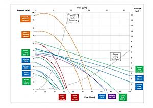
Nick
The first thing is to add the Pierburg electric water pumps to the discussion. These are probably best know as "The BMW pump", but its actually a range of pumps for different applications. They range from the 15W WCP circulation pump (for heating and cooling when the engine is off) to a 1100W monster to replace the biggest mechanical pumps. An electric pump is still a bit of a novelty, but following BMW's lead, I think they're likely to become commonplace. There are probably four of interest:
CWA 50 . Circulation pump, 50W , 6000 rpm, 24 lpm @ 0.60 bar
CWA 100 Circulation pump, 100W, 7200 rpm, 30 lpm @ 0.85 bar
CWA 200 Coolant pump, 200W, 4500 rpm, 120 lpm @ 0.45 bar
CWA 400 Coolant pump, 400W, 10000 rpm, 150 lpm @ 0.80 bar
The CWA 50 is used as a charge cooler pump on the recent BMW V8TT engine, and the CWA 200 is used as the coolant pump on a wide range of recent BM's. The circulation pumps have relatively low flow and high pressure, while the coolant pumps are obviously high flow. Like all good pumps, they're specified by their flow rate under pressure, so we know what their installed performance is going to be. Contrast that with the Meziere WP136S, which simply claims 20 gpm / 76 lpm open pipe. Like the Meziere, the big Johnson and Davies Craig pumps also claim high open pipe flow, but when I put the Pierburgs onto my Flow Characteristics chart, an interesting picture emerges.
For the purposes of charge cooling, these pumps rock. If you look at the Charge Cooler Resistance curve, which gives an indication of the pressure/flow characteristics for a typically constricted charge cooler system, you can see which pumps will give good installed performance. The CWA 50 beats all-comers so far, and the 100 is better still, even achieving one bar pressure differential at low flow rates. For charge cooler systems, these are two meaty pumps. I believe the CWA 100 is what Renntech use for their new IC pump, and it seems to be exactly what's needed. Shame about the silly price.
The CWA 200 & 400 coolant pumps are off the chart, flowing over 100 lpm, and I didn't even try to plot them. They're huge, but you can see they meet different requirements. Where the 50 & 100 (like the Bosch pumps) fit the Charge Cooler Resistance curve pretty well, the 200 & 400 are closer to the Engine Resistance characteristic. In fact, the Pierburg stats tend to back up what I've supposed are the installed characteristics for IC and engine cooling, with a big difference in the pressure/flow curves. If anything, I think the differences should be even greater, with an even steeper IC curve and a shallow coolant curve.
The other thing that's interesting about the Pierburg pumps is that they facilitate electronic variable speed control. They can be slowed down almost to a stop, for fast warm-up and to save electrical power. In theory, they can control water flow well enough to avoid the need for a thermostat. That might not avoid hot spots in the engine during warm-up, so I don't believe anybody has actually implemented that yet, but it sounds ideal for a charge cooler.
There's lots of interesting discussion, brochures and information about the Pierburg pumps here:
http://north.america.kspg-ag.com/ind...id=2195&lang=2
http://www.pierburgspa.it/pdfdoc/ksp...olant_pump.pdf
http://www.kspg.com/fileadmin/media/...lmittelp_e.pdf
https://mbworld.org/forums/w211-amg/...now-about.html
https://mbworld.org/forums/w211-amg/...-bmw-pump.html
https://picasaweb.google.com/renntec...50086765057074
And here's my updated spreadsheet - note that the scales have been expanded since last time, and I've added imperial flow and pressure scales. I've been meaning to do that for weeks; its frustrating when manufactuers quote specs in so many different units; its difficult to make fair comparisons otherwise, so here they are.
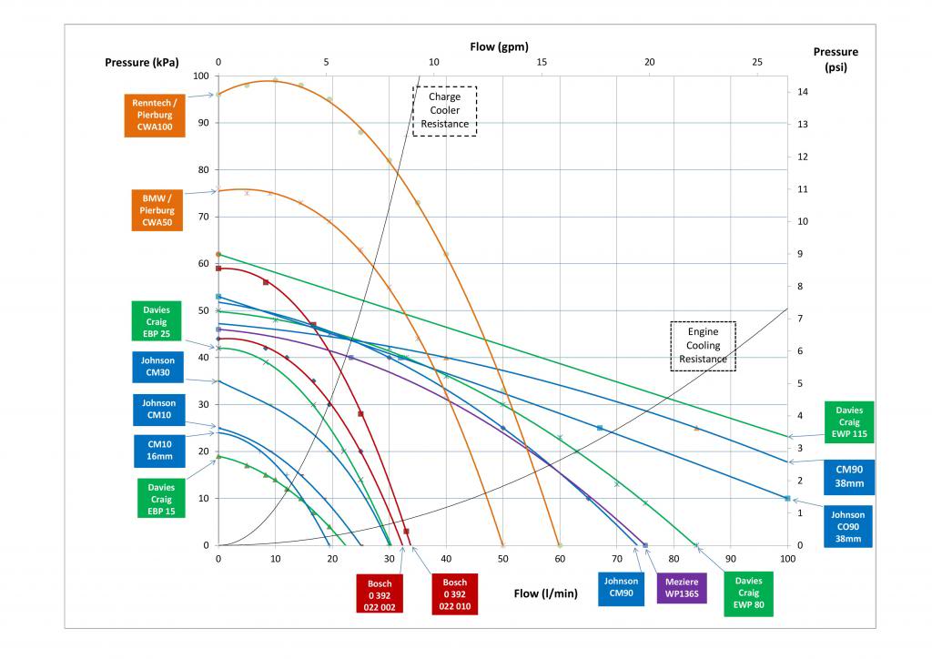
Nick
Last edited by Welwynnick; 04-21-2013 at 05:39 AM. Reason: Added jpeg
04-21-2013, 09:22 AM
#25
Super Member
Join Date: Nov 2012
Location: Germany
Posts: 698
Received 16 Likes
on
13 Posts
C215 CL55 AMG, W124 500E, W210 E430, W124 300E
Nice Nick,
what do you think about this report?
https://mbworld.org/forums/w211-amg/...-vs-wp136.html
what do you think about this report?
https://mbworld.org/forums/w211-amg/...-vs-wp136.html


