When you click on links to various merchants on this site and make a purchase, this can result in this site earning a commission. Affiliate programs and affiliations include, but are not limited to, the eBay Partner Network.
OK, so you start off by removing the right side air cleaner and the Y-shaped air duct that leads to the turbo. MB calls the “right side” of the engine the USA Passenger side of the engine so keep that in mind. In order to remove this, you start by removing the cross brace, and the access panel on the cowl. The cross brace is held by 4 large Torx screws, and the cowl access panel by a single 10mm bolt. I also pulled the rubber gasket from the cowl to get it out of the way.
The Y-shaped air duct is removed by loosening the three hose clamps with either a flat blade screwdriver or a 7mm socket wrench. Don’t try to pull the duct loose until you have loosened the air filter box on the right side first. You do this by unscrewing the two Torx screws that hold it in place. If you try to pull the air duct loose without doing this, you can damage it. The front screw is just below the oil fill cap and the other (a special bolt about 3” long) is a bit hidden, toward the fire wall. I pulled both bolts, then moved the assembly toward the right shock tower and lifted it out. There is a duct that connects to the filter housing that you should pull as well that leads to the grill. Set these aside. Now that you have the air cleaner assembly out, you can safely remove the Y-shaped duct and the associated gaskets. There are several electrical connectors on this duct, I mark them with blue painters tape and write a code on them to help me remember where they go during reassembly.
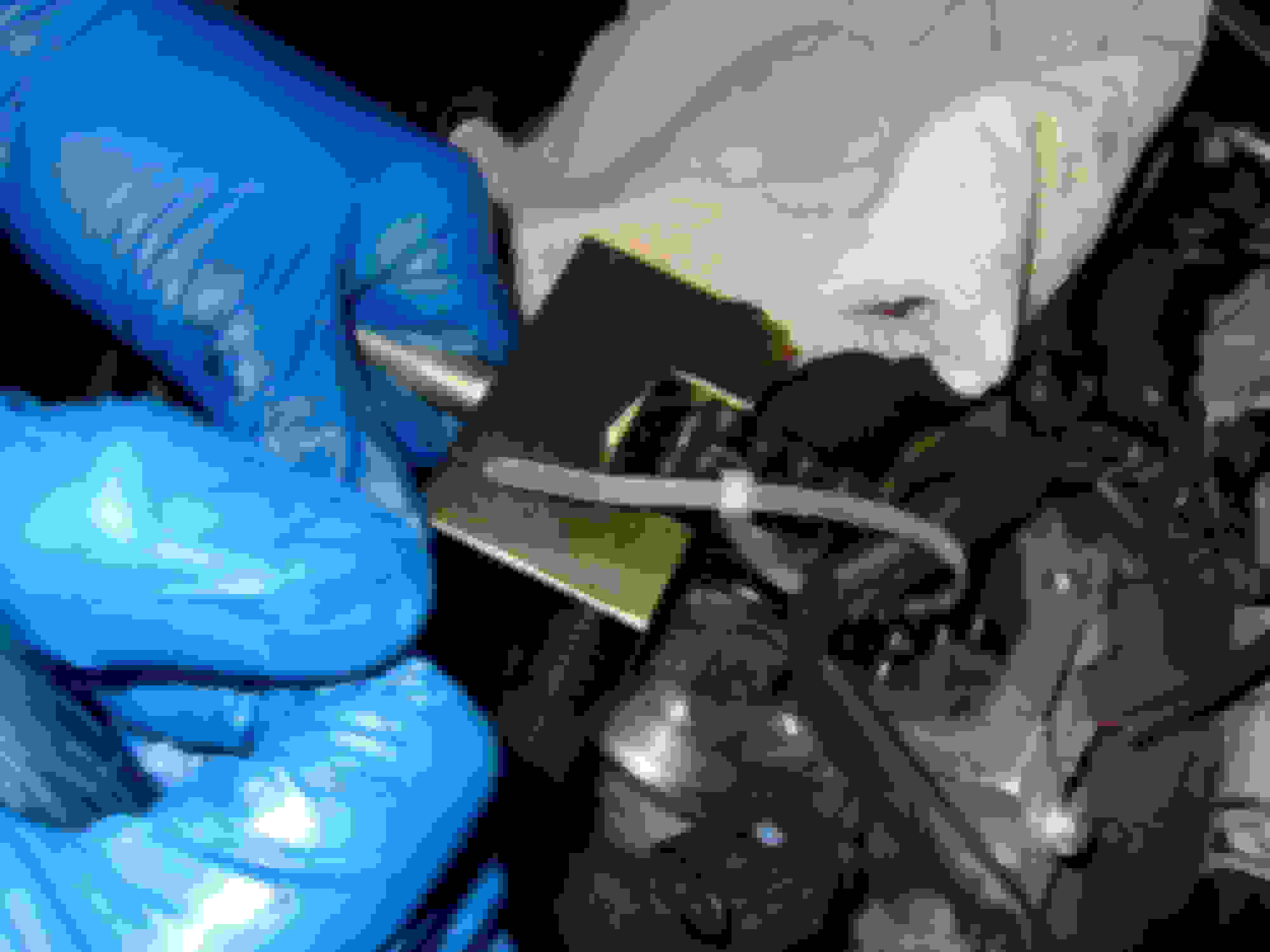
Next you need to remove the return fuel line. This is a black fuel hose that attaches at each injector. The hose is in sections and connects with a circular connector on each injector. You carefully lift up on the plastic circular piece until you hear a clicking noise. I used a couple screwdrivers and it takes a bit of force. Disconnect all three, then life the hose assembly out of the way and set it aside.
Next you disconnect the hard lines leading from the fuel rail to each injector. In the documentation, MB cites a special tool for this which is basically a crows-foot socket. I didn’t want to buy the special tool so I used flare nut wrenches, it was a 17mm. If you’ve done brake work, you have these in your tool box. If not, then it’s time to buy a set, they are very useful. Loosen each nut both at the injector and the rail, and lift out the hard line. You can only do small turns due to limited space, and turning the wrench over each time helps. I have a three tiered cart in the garage and had lined each shelf with cardboard, and set each injector line in the order that I removed them, marking the cardboard with a Sharpie so I would know where each went.
On the back of the valve cover near the firewall is a bracket with several connectors on it. It’s held by two Torx screws. Those screws don’t go all the way through, so after you remove the bracket and bend it down out of the way, re-insert the screws so you don’t forget where they go.
Now you can remove the fuel rail. First disconnect the hard line that comes over from the other side, then remove the two Torx screws that hold it to the valve cover. Again, reinsert the screws so you don’t lose them. Some fuel will come out when you do all this, just keep a rag handy to clean up any that spills.
Next you pull the injectors, which means introducing special tool #1 that I had to buy. In order to pull the injectors, MB calls for a slide hammer. The one I bought was actually for a VW/Audi application, but it was the most cost-effective that I could find. It has several adapters, one of which is M14 x 1.5 thread pitch, which is what the top of the injector has on it (where you disconnected the hard line.) You thread that fitting onto the top of the injector, then thread the slide hammer rod onto it. Then you slide the hammer weight up sharply and it pulls the injector out of its bore. Again, I placed these in order on my cart and marked the order in which I removed them. The factory manual calls for cleaning the bores by coating a round metal brush in a special grease, and scrubbing them, but mine where pretty clean given the low miles.
Now you need to re-install the intake camshaft again and match up your timing marks. When I reinstalled mine, I coated the bearing surfaces with Red Line assembly lube, but if you don’t have that handy, then at least get some motor oil on there so you don’t have it dry fit. Once the camshaft is back in, install as many bolts as you can to reattach the sprocket to the camshaft, and torque the bolts to 160 Inch Pounds. Before you start rotating the engine to check timing, install your NEW tensioner into the side of the cylinder head. Torque it to 60 pound-feet. Now, using your breaker bar, rotate the engine around by hand and verify that your dots are linking up at TDC, and that the timing mark on the crank pulley is lined up at 0 degrees. Don’t just do this once, rotate the engine through several cycles and check the timing marks each time. When you are convinced it is right, you can start to button everything up again.
If you didn’t clean up the cylinder head and valve cover when you removed it, now is the time to do so. You need to get all that old sealant off of there and get a clean surface so that you can glue it down again. MB cites a special cleaner for doing this, but I just used carb cleaner and a rag. I stuffed rags down into all the crevices of the cylinder head so that none of the bits would fall down there. And when I was done cleaning I used a shop vac to try and clean them all up. You need to have an oil free surface to get a good seal and prevent any leaks.
Once you have the surfaces suitably clean, you need to get a tube of Loctite 5970 and put a 1.5mm bead all around. MB specifies a path to lay it down, and I found that the tube that I bought fit into a small caulk gun, which made it easier to dispense. You’re supposed to get the entire thing done within 10 minutes so that it doesn’t start to cure. You can see how to lay down the bead here:
Place the valve cover on the cylinder head and screw in all your bolts finger tight. Then, starting in the middle and working your way out (just like when you removed them), you torque the bolts in 3 stages:
1. 35 inch pounds
2. 53 inch pounds
3. 80 inch pounds
There are something like 30 bolts, so this takes a while and it’s easy to miss a bolt, so take your time and check every one. Torque on these is critical because it’s what holds the camshafts in place.
After you get the valve cover back on, reassembly is, as they say, the reverse of disassembly.
When reinstalling the injectors I again used the slide hammer to seat them properly. I installed new copper washers and o-rings on the fuel return line. The long bolts that hold the injectors in place are, I believe, one time use, but I re-used them and just put a small bead of blue Loctite about an inch from the bottom. These are torque to yield bolts, so you start by applying 62 inch-pounds, then turn it 90 degrees, then another 90 degrees.
The hard lines for the fuel system are torqued to 20 and 24 foot pounds, but since I didn’t have the crows foot socket, I just did it by feel using flare nut wrenches. You have to pay particular attention to how everything goes back together. Between the fuel lines, the fuel return line, and all the injector wiring, if you don’t get it all back in the right spot, you can find it difficult to get the air cleaner back in place, especially that foam rubber spacer. It helps if you take photos when you are taking it apart and reference them during reassembly.
Once you have it all together, check every connection again to ensure you have it buttoned up, and now it’s time to start it up. Because you’ve drained the fuel from the lines, it takes a few tries to get the engine to start. In my case, because I had taken off the left side as well and all those lines, it meant 5 tries, but it started up fine and settled into a normal idle.
How long did it take? Good question. I have two small kids and I travel a lot, so I was working an hour or two here and there, along with some marathon sessions when I could get the change. I’m going to guess it took me 30 hours, plus another 3 hours of a helper. If I had not removed the left side cylinder head cover too, I bet I would have saved 10 hours; that was a real bear, especially the EGR valve which is up under the cowl and in a terrible spot. I bet if I did this job again, I could get it down to 15 hours; there is one steep learning curve after another.
Now we turn our attention to the front of the valve cover where there is what’s referred to as a vacuum pump. First you remove the black plastic box that is in front of it (I honestly don’t know what this is, but it appears to hold oil vapor or something as it’s hollow) by removing 3 Torx screws and lifting up and towards the front. There is an electrical connector that you then disconnect and move out of the way.
Next you remove the four Torx screws from the vacuum pump itself and make sure that you grab the rubber coated gasket with it. This thing is filled with oil, so let it drain in a pan once you set it aside.
Now you remove the crankcase ventilator from the back of the valve cover. It’s held on by two Torx screws, neither of which are within view. Use a mirror to find them, then put a finger on them to guide your wrench onto them. Once the bolts are off, wiggle it back and forth to remove it, it’s held in with an o-ring and pops out pretty easily.
Now it’s time to remove the valve cover. MB specifies a specific order for removing the bolts. This is because the valve cover also serves to hold the camshafts in place rather than using cam trays. I’m sure this saves them some money, but if you screw up the cover during removal, you’re replacing the entire head (they are a matched set), so don’t screw it up. As a result, torque on these bolts are critical and the removal and installation order is designed to minimize stress on the camshafts, which are hollow and can’t take much stress. I don’t think the *exact* order is critical, just that you do it approximately correct. Basically you start in the center and work your way out. So you start with the center two bolts in the middle of the cover (loosen only, don’t remove them) then you loosen the outer two bolts in the center. Next you move forward to the next set of bolts and loosen them. Then you move to the set of bolts to the rear of the original center set and loosen them, alternating front and rear until all the bolts are loose. Continue in stages until you have all the bolts out. Again, set the bolts in the EXACT order that you removed them, on a piece of cardboard, so you know how they go back in. The center bolts have a sealant on the top to keep oil from seeping out.
Now it’s time to actually remove the cover itself. First, verify that you have ALL the bolts out. There are (I believe) 30 of them, so it’s easy to miss one. Don’t mess with this; ruin this valve cover and you are in a world of hurt and will have to replace the head. Instead of using a gasket, MB uses Loctite 5970 sealing compound, which means that sucker is basically glued on there. You’ll use your slide hammer again to free it. Now, I didn’t have the adapter to use my hammer (which again, was for a VW/Audi application) so I had to make one. I used an aluminum ‘C’ that I had laying around, and drilled a hole through which I threaded one of the cover bolts. I used a hole near the front of the cover and inserted my adapter, then attached the tool using the same adapter for the injector (the photo is helpful here.) In lieu of this you can just buy the MB adapter, which I don’t think was that much money, I just neglected to buy it. Now, I’m going to tell you, that the first time you do this it’s nerve wracking. You are cognizant of the fact that if you mess up here, that you are truly screwed, so your brain doesn’t really want you to use too much force. But you really have to pull that weight HARD to get the cover to loosen. The first couple goes, nothing will happen, but eventually you’ll hear the tone of the “whack” that the tool makes when you hit the end of the slide hammer, change. That means you’ve broken the seal. Another hit or two and it will pull loose. Breathe a sigh of relief. At this point, the camshafts are exposed.
Next you set the #1 cylinder (i.e. the one closest to the front of the engine) to Top Dead Center (TDC.) Top dead Center means that both valves are closed and the piston is at the top of the compression stroke. The easiest way to do this is to put a breaker bar with a 27mm socket on the crankshaft pulley nut and turn it until the camshaft lobes on the #1 cylinder are pointing up and towards one another. As you get close, start looking from behind towards the front and you will see that MB has cast some small holes in the cam gears. At exactly TDC the dots will be aligned perfectly and you can confirm TDC by looking at the timing mark on the crankshaft pulley which will be at 0 degrees. At this point, I highly suggest taking a grease pencil and filling in those holes so they are easy to spot, and also the 0 degree mark on the crank pulley.
Now, leading up to this point you’ll want to start pulling the bolts that hold the sprocket that holds the chain, because you need to remove it. There are three bolts, but you can only access 1 or 2 of them at a time. There is also a pin that helps you locate the sprocket as well. If you forget to do this ahead of time, then you have to rotate the engine around a full cycle to get it back again.
Once you have all three bolts off the sprocket, and the engine at TDC, then you can pull off the sprocket and pull it aside. I used zip-tires to hold the chain to the precise point on the sprocket so I didn’t mess up the timing, and also since you are going to separate the chain, you don’t want one end falling into the timing case, so I used a couple to hold both ends in place. Now it’s time to remove the tensioner from the cylinder head, and set it aside. Put a pan under there, as engine oil will drip out of the hole and make a mess of your floor. Then you remove the two bolts which hold the brackets which retain the intake camshaft, and pull the camshaft out. It doesn’t take much force.
Now, I’m going to tell you that this is where I started to think too much. I decided to pull the left side valve cover as well because I couldn’t wrap my head around not knowing for certain that the other side of the V was in time with the right side. While this was excellent peace of mind, and helped me sleep, it was a complete disaster because removing the left side valve cover is 10x more difficult than the right side. My advice is: don’t do it. I’m going to guess that it added a solid 10 hours to an already long and tedious job.
Moving on; time to separate the chain. At this point, you have the camshaft out, you have the sprocket zip-tied to keep the chain from falling, and you have the chain zip-tied to the sprocket to keep it all in time. Now is time to pull out special tool #2, the timing chain separating and riveting tools:
I bought mine off eBay, I think about $60 vs. a hell of a lot more for the official MB tool and other alternatives. There are two tools, and now we need the separating tool. The tool is a large U shape, and either end has a bolt in it; both are hollow. The larger hollow bolt has another smaller diameter bolt inside it, and holds a riveter. The tool came with several rivets for pushing the chain link out. At this point, you need to look at your new chain. The chain has two small dots indented into the top of each link. Check to see how your new chain, properly oriented, will mate with the chain in the vehicle. Note which pin you will have push out so that you can link the new chain to the old chain, or else you’ll have to rivet out another pin.
THIS IS IMPORTANT: stuff some rags into the spaces in the timing case so that you don’t drop anything down in there. If you do that, you’re screwed.
Place the tool onto the chain, make CERTAIN that you have the pin aligned properly and start cranking the nut on the tool to push the pin out. If you don’t have it aligned perfectly, the pin will hit the other side of the tool and prevent you from pushing it further. If you apply more pressure when this happens you could easily break the tool (remember, hollow bolts.) Eventually, the link will press out into the other hollow bolt on the back of the tool. Back the large bolt back out, and pull the tool away. You now have a separated chain.
Next step is to take the temporary link that comes with the special tool and link your new chain to the old chain. The temporary link has three parts. 1. A link with two pins that are grooved on one end; 2. A solid link, and; 3. A link that with cut outs to allow you to snap it into the grooves on the pins of #1.
What you do it place the new chain in position, insert #1 through the holes in the two chains, until the ends are visible. Then you insert link #2 over them (it’s basically a spacer), and finally you push link #3 onto the pins and lock it in place. Mine was very tight, so much so that I was worried about breaking link #3. So I took a micro file and filed the surfaces a tiny bit to make it easier to clip onto the grooves on the two pins. At this point, the two chains are temporarily riveted together into one long chain. In the photo, the temporary link is to the right of the brass colored link (no, I don’t know why there are different colored links.)
Reinstall the intake camshaft. You set it in place, then press down to compress the valve springs on (I think) cylinder #3. It take a little force, but not too bad. Now pull up the sprocket and set it back in place on the camshaft, ensuring that you align your dots. Take your time, this is critical that everything is aligned. Insert and tighten one bolt to secure the sprocket to the camshaft.
At this point you need a helper; not just any helper, somebody who is as good as you are with cars. Take your time and wait until that person is available; you’re not doing this yourself.
The factory has another special tool (the damn Germans LOVE special tools) for this procedure. It bolts onto the cylinder head and prevents the chain from skipping a tooth while you are pulling it through. This tool costs something like $430, so no way was I buying it. I considered making one myself, but I thought about it a bit and came up with this:
That’s a pry bar inserted between the chain and the cylinder head. It worked fine, but the guy holding it, and feeding the chain in and out needs three hands, but you’ll figure it out. This is not optional; you don’t want to mess this up and consequently mess up the timing.
This is how this goes; person A uses the breaker bar and the 27mm socket to turn the engine clockwise. Person B feeds in the new chain, and pulls pretty hard on the old chain to pull it out. All the while, person B has to make sure that the new chain is riding on the sprocket fully (to keep the camshafts moving and preserve the timing) and that the old chain is coming out. This pulls the new chain through and will eventually replace the old chain with the new one.
That sounds pretty simple right? But remember, the engine is at TDC, which means that cylinder #3 valves are compressed, and as soon as you start rolling that camshaft, the energy contained in those compressed valve springs is going to release. Fast. The first time this happens it will scare the crap out of you, so be prepared for it. Keep the pressure on your hold down device, and keep the pressure on the sprocket and pull that old chain out. After the first valve springs release, there will be some slack until the left side of the V catches up with the right, then person A will feel even pressure again while turning the crank nut. Person A continues rotating the nut and Person B continues feeding and pulling until the next time it jerks (this is roughly 4 partial turns because you only have so much space to turn the crank nut) until the new chain is fully in. Again, take some deep breaths. This whole process took about an hour (or maybe it just felt like it) because Person B has to continually find a place to put the old chain and reset the new chain which acts like a snake and generally doesn’t cooperate. I don’t have any photos of this process (because there was no way to) but you can find an official MB video on YouTube with a few searches, which is for a gas engine but it’s a very similar procedure.
At this point you have the new chain in place and the old chain is hanging down into the engine bay. Person A can now zip tie the new chain in place on the sprocket (both ends if you want to be safe) and then you can unclip the temporary link and lift the old chain out of the way. There should not be a gap between the links in the chain, instead you should be able to insert the double-pin portion of the special tool into the chain, closing the chain with no slack. If you’ve got slack, you’re going to have to really be careful and re-time the engine, but if you’ve done everything right yours should look like the photo below (the long link is the tool to assist in riveting the center link into the chain.)
The next step is to rivet the chain back together. If you’re helper is still hanging around, you’re in good shape. Mine wasn’t so I left the sprocket on and fumbled through doing this with it in place. The difficulty in this is that, despite the WIS showing a photo of the chain being riveted with the sprocket in place, in reality the special tool hits the gear on the camshaft and puts it at an angle that won’t allow you to use it properly. So that means that you need to pull the camshaft again. My suggestion is to carefully mark the gears on the intake and exhaust cams so you are CERTAIN of being able to put them back into place while preserving the timing. This is absolutely critical. Now, again, place some shop towels into the timing case area so that you can’t drop any small parts down into the space. Once the camshaft is out, you can install the center link in place, push the temporary link through to hold it in place, then push the new link from your chain kit up against it. If you look back to the photos of the special riveting tool, you’ll notice four black blocks at the top of the case. This first step involves the block on the far right of the photo, as well as the block second from the left. You install them in the tool, and fit the tool over the new chain, so that the pushing block will push the new 2-pin link into the center link that you have held in place temporarily. This process forces the pins through that center link, and pushes the temporary link out. Continue to push the 2 pin link in until it is the same depth as the links next to it, then remove the tool and install the second set of blocks from the kit.
So now you have the center link properly installed and you need to install the outer link. If you look closely at the pushing block that you have in your tool, there is an indent the exact shape of the end link, with a magnet that is flush to the block. You take the new link, and stick it to the magnet. Then you install the block into the tool and again, position the tool over the chain and press the new end link onto the two pins. Continue pushing until it is the same depth as the links adjacent to it.
Now you have the new link in place, and the final step in the process is to crimp the ends of both pins to retain the link in place. If you look at the other links of the chain, you’ll see that the pins are dimpled in on the ends, 180 degrees apart. Now look at the pushing block that you just used, and you’ll see that if you rotate it 90 degrees, it will have a V-shaped indentation on it. Install it in the tool so that V-shaped indentation is facing the other side of the tool, and position the tool over the new link, centered on ONE of the pins. Crank down on the bolt and push the V-shaped indentation onto the pin. The spec says to crank it to 24 ft-lb but good luck getting a torque wrench on there while your holding all this with your three hands. OK, maybe if you have a helper. Back it off, then do the next pin. Inspect your dimples to ensure they look as good as the ones in the other links, and if not, press it in again. If they look good, pat yourself on the back, you’ve got a continuous chain in there again.
Last edited by sak335; 04-22-2019 at 09:55 AM.
Reason: found a mistake
Now you need to re-install the intake camshaft again and match up your timing marks. When I reinstalled mine, I coated the bearing surfaces with Red Line assembly lube, but if you don’t have that handy, then at least get some motor oil on there so you don’t have it dry fit. Once the camshaft is back in, install as many bolts as you can to reattach the sprocket to the camshaft, and torque the bolts to 160 Inch Pounds. Before you start rotating the engine to check timing, install your NEW tensioner into the side of the cylinder head. Torque it to 60 pound-feet. Now, using your breaker bar, rotate the engine around by hand and verify that your dots are linking up at TDC, and that the timing mark on the crank pulley is lined up at 0 degrees. Don’t just do this once, rotate the engine through several cycles and check the timing marks each time. When you are convinced it is right, you can start to button everything up again.
If you didn’t clean up the cylinder head and valve cover when you removed it, now is the time to do so. You need to get all that old sealant off of there and get a clean surface so that you can glue it down again. MB cites a special cleaner for doing this, but I just used carb cleaner and a rag. I stuffed rags down into all the crevices of the cylinder head so that none of the bits would fall down there. And when I was done cleaning I used a shop vac to try and clean them all up. You need to have an oil free surface to get a good seal and prevent any leaks.
Once you have the surfaces suitably clean, you need to get a tube of Loctite 5970 and put a 1.5mm bead all around. MB specifies a path to lay it down, and I found that the tube that I bought fit into a small caulk gun, which made it easier to dispense. You’re supposed to get the entire thing done within 10 minutes so that it doesn’t start to cure. You can see how to lay down the bead here:
Place the valve cover on the cylinder head and screw in all your bolts finger tight. Then, starting in the middle and working your way out (just like when you removed them), you torque the bolts in 3 stages:
1. 35 inch pounds
2. 53 inch pounds
3. 80 inch pounds
There are something like 30 bolts, so this takes a while and it’s easy to miss a bolt, so take your time and check every one. Torque on these is critical because it’s what holds the camshafts in place.
After you get the valve cover back on, reassembly is, as they say, the reverse of disassembly.
When reinstalling the injectors I again used the slide hammer to seat them properly. I installed new copper washers and o-rings on the fuel return line. The long bolts that hold the injectors in place are, I believe, one time use, but I re-used them and just put a small bead of blue Loctite about an inch from the bottom. These are torque to yield bolts, so you start by applying 62 inch-pounds, then turn it 90 degrees, then another 90 degrees.
The hard lines for the fuel system are torqued to 20 and 24 foot pounds, but since I didn’t have the crows foot socket, I just did it by feel using flare nut wrenches. You have to pay particular attention to how everything goes back together. Between the fuel lines, the fuel return line, and all the injector wiring, if you don’t get it all back in the right spot, you can find it difficult to get the air cleaner back in place, especially that foam rubber spacer. It helps if you take photos when you are taking it apart and reference them during reassembly.
Once you have it all together, check every connection again to ensure you have it buttoned up, and now it’s time to start it up. Because you’ve drained the fuel from the lines, it takes a few tries to get the engine to start. In my case, because I had taken off the left side as well and all those lines, it meant 5 tries, but it started up fine and settled into a normal idle.
How long did it take? Good question. I have two small kids and I travel a lot, so I was working an hour or two here and there, along with some marathon sessions when I could get the change. I’m going to guess it took me 30 hours, plus another 3 hours of a helper. If I had not removed the left side cylinder head cover too, I bet I would have saved 10 hours; that was a real bear, especially the EGR valve which is up under the cowl and in a terrible spot. I bet if I did this job again, I could get it down to 15 hours; there is one steep learning curve after another.
Mine had 54,600 miles at the time it began rattling on startup. I immediately pulled it from the road (I have a third car...) to avoid damaging the sprockets too. The chain was well stretched (stupidly I didn't measure the new one so I can't tell how badly) but there was a ton of slack in the chain that wasn't present after the job was done, and the noise is no longer present at cold startup.
Wow what a job so glad that I paid to have mine done!! I had just finished the oil cooler repair which took way to long and decided I didn't have the energy or time to do the chain on top of it. I believe it was about a $2,000 job at the dealer.
It's pretty disturbing to hear worn out timing chain at under 100,000 miles - they should last the lifetime of the engine if they were made of proper materials, sized and lubricated properly.
Any speculation why these wore out prematurely?
Could it have anything to do with the recommended long engine oil chance interval?
I'm not sure what the OEM manufacturer is, but I used a Febi/Bilstein replacement. I'm not sure the actual chain is the problem; it's impossible to tell without any data.
Yep, I've seen the tensioner looking "out of spec" posts...I am really struggling with these engines needing chains at <100k miles (or even 200k)
I have worked on diesel engines many years and stretch chains are rare(even marine at high HP duty cycle), anyway I would love to see confirmation of stretch directly on the actual chain, easy to see by pulling on it at the sprocket.
OM642 ruins chains at low miles=design issue for shure, and I bet MB will eventually be hit with a class action to pay for all the repairs(just like balance shaft issue on the M272 gasser)
"Keep your receipts".
formerly drove a 2010 ML350 BLUETEC, currently drive Mazda, Chevrolet, and Toyota
Originally Posted by samaritrey
Late reply but for my car I believe the oil either was not the correct type or got to low during its life before I bought it.
My engine's failure at 82K miles was due to a combination of improper oil from the dealer along with faulty parts / engine design, as detailed in my thread here: https://mbworld.org/forums/diesel-fo...ne-seized.html
Yeah I think stretched chains on those are rare because HD & marine Diesel engines usually have gear driven camshaft etc.
It would be pretty expensive to build V6 DOHC engine with gear driven camshafts which is why we have a loong chain to drive them!
I am getting my engine oil analyzed at each oil change and becoming more and more convinced that the factory recommended 10,000 mile oil change is part of the premature chain wear problem.
The iron level has been 54, 52, 115 & 59 ppm depending on how many miles on the oil (6,700 - 9,300 miles), VS. 47, 39, & 30 ppm with 2010 VW TDI with 9,000 - 10,000 oil change interval.
The TDI has no chain, it has belt driven camshafts. The belt is supposed to be changed regularly $$.
My 2008 BlueTec has just over 150,000 miles and so far the original timing chain is fine, but I am pretty convinced the extra iron is coming from normal timing chain related wear.
It will have future max 7000 mile oil change for sure (mine is almost all highway driving).
My engine's failure at 82K miles was due to a combination of improper oil from the dealer along with faulty parts / engine design, as detailed in my thread here: https://mbworld.org/forums/diesel-fo...ne-seized.html
It's too bad, but as I recall you had incorrect oils mixed and went way way over the 10,000 mile oil change interval, combination of which caused oil turning to a sludge!
Not much in common with premature timing chain wear / replacement I think, but please correct if I am wrong.
arto_wa:
Wow those iron numbers look high for a road vehicle, with relatively short interval(but I am no expert on the V6 Blutec, would need to compare others), they look like a heavy use marine diesel-type number.
I have older I6 CDI(no DPF), still uses chain(shorter run, easy 50%?) but the iron numbers are in <20ppm range, see below. I change under 9 to 10k miles.
Maybe it is a tradeoff with the oil, no-dpf can use "better" oil, ie Delo or M1 TDT 5W-40. I meant the V6/V8 Mercury marine diesels that seem to be doing OK, "so far" .(with timing chains, tensioners so-so)
I agree; based of what I have read I also think the higher iron content is related to the DPF compliant oil.
OP here. In my case, the vehicle was maintained to the letter of the maintenance schedule with the approved oil. The chain started making the telltale rattle at startup so I parked it and began the replacement process. I measured the new chain and the old chain and it was stretched 11mm at less than 55k miles. I've changed my oil change interval to 6k miles as I believe that the oil just can't take the 10k mile drain intervals but have no data to back that up. I'm 10k past the chain replacement without issues and will likely replace the tensioner every 25k as a preventative measure as well. I'm extremely disappointed in this vehicle, and M-B in general, but I see no realistic way to make them accountable aside from never buying another vehicle from them. This will be my first and last Benz.
sak335, I am truly sorry for your experience, and double thanks for posting a detailed procedure(probably while cursing MB!)
Sorry to say that 11mm strech does not sound bad at all on such a long chain, but obviously it fixed the slapping----I am still confused by these low-miles chain issues.
Last question, did you change or inspect any of the guides? They are thick and wear could affect symptoms.
It shure seems like some fresh-out engineer at MB decided to run the whole V valve train in one long chain instead of 2 or more, chain/guides must be in incredible stress, specially the "reverse" side of the V, I thought that was why other engines I have seen use 2 chains.


 03-09-2017, 09:19 PM