
••• Project Stock to Awe •••

 05-06-2007, 11:01 AM
#51
Out Of Control!
 Finny's going to autograph his own engine...


")

 05-06-2007, 09:13 PM
#57
Super Member
Thread Starter
I used to design & build parts and service small to very large food processing machines from Germany & Switzerland some time ago. These days I run a small computer IT company and Rebuild Pinball machines for fun.
Anyone with basic mechanical skills can rebuild these engines until you hit the bottom end. This is where you obviously require a very skilled engine builder with specialized tools & machines. You can always sub contract these items out and do the final assembly yourself. A little tricky though.
If one dose attempt DIY, make sure you have WIS on hand.
 05-07-2007, 04:15 PM
#60
Senior Member
Join Date: Jul 2003
Location: MELBOURNE AUSTRALIA
Posts: 323
Likes: 0
Received 1 Like
on
1 Post
A160 CLASSIC (The Tardis), VW Passat Diesel
WIS??? Love the see the dyno results when it is all back together and firing.... Did it take long to get the engine out??
Love the see the dyno results when it is all back together and firing.... Did it take long to get the engine out??
05-07-2007, 09:41 PM
#61
Senior Member
Damn man! Nice job!
I'm a little freaked by that PCV issue. I have 18K miles on mine. Think it's already like that? Is it too late for the catch can mod?
I can't believe MB designed that so poorly...
I'm a little freaked by that PCV issue. I have 18K miles on mine. Think it's already like that? Is it too late for the catch can mod?
I can't believe MB designed that so poorly...
05-08-2007, 12:54 AM
#62
Banned

Join Date: May 2004
Location: Richmond Hill, Ontario
Posts: 3,797
Likes: 0
Received 2 Likes
on
2 Posts
2003 E55 AMG
Its never too late!
Also, there is a very simple way to clean out deposits from the engine... There are chemicals that you can buy that will do the trick, or just plain old distilled water..
A trick I've used many times in the past is:
- Go for a drive and once you come back pull the airbox off the car so that the TB is exposed. Its important that the car is at operating temperature when you do this.
- Pour some distilled water into a spray bottle
- With a helper in the car, have him rev the car to about 2,000RPM - 2500RPM (just enough to open the throttle plate a bit)..
- Mist the water into the throttle body.. Start off slowly and listen for the idle.. Keep misting into the TB until you go through 8oz of water.
- The water will immediately turn into steam when it enters the combustion chamber and will act as a cleaning solution to remove all the built up gunk.
- This is a benefit that people see who run water injection systems.. not only do you get the cooling effect, but the cleaning effect also.

 05-08-2007, 12:20 PM
#64
Super Member
Thread Starter
05-08-2007, 12:26 PM
#65
Super Member
Thread Starter
After 18,000 miles or 29,000K's should be nothing like mine so get the catch can ASAP!
Last edited by Finny; 05-08-2007 at 12:30 PM.
05-10-2007, 09:58 AM
#66
Super Member
Thread Starter
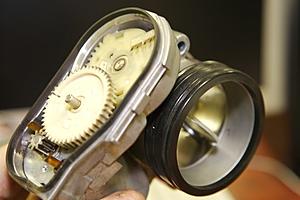
G'day Fellers, here's another update....
There's been much chatter about the super charger by-pass throttle body being open or shut at different times making us paranoid about whether or not we're losing power.
To date... I've never seen a solution that can indicate in real time if this little T/B bludger is open or shut.
I suppose you could shove a stick up there and feel around but it could damage the charger... now we don't want to do that now do we! So I have a more simple solution... stick a magnet inside the by-pass so when the butterfly valve is shut it triggers a normally open reed switch contact closed where you can hook it up to a LED inside the cockpit.
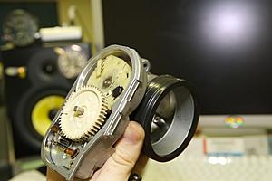
See the following shots on how it was done.
I sourced the reed switch from a Burglar Alarm supply joint. The magnet and reed switch was stuck on with Loctite silicone. A Dremel was used to make a hole in the Butterfly cog. The photos are fairly self explanatory. I'm also going to add the LED to the boost indicator so can I see it all in one spot.
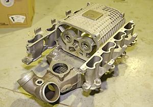
Was checking out Ebay recently and found the induction system of an E55 for 2k USD or landed to my door in Australia for $2850 Ausie Bux which I think is a bargain for a spare charger with all the bells and whistles... See photos... You never know what you'll find. Mmmm SLR Inter-coolers..... "SEARCH"
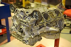
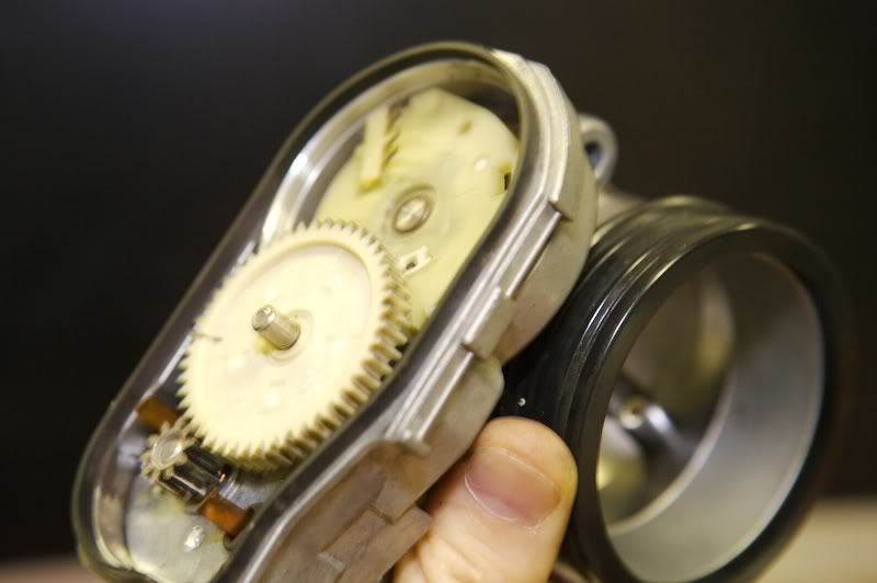
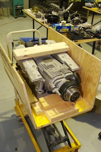
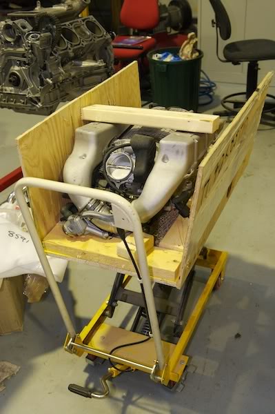
Engine mounts added and ready for next step...
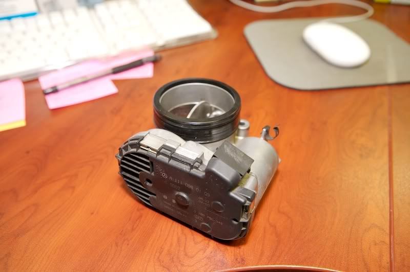
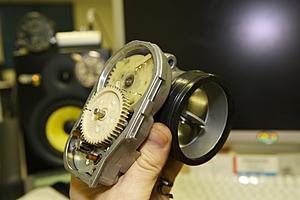
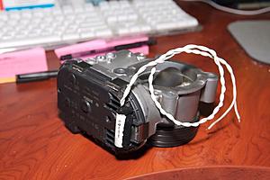
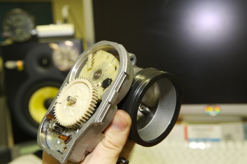
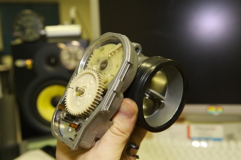
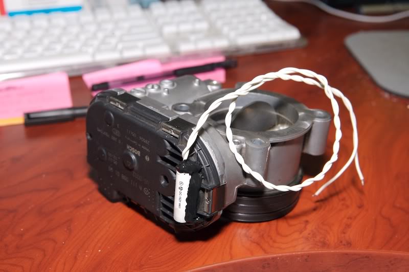
Bypass Throttle Body. (note: This was off an 03 model, I know there are some that are covered in rubber)
Lid off, just remove the clips that snap off.
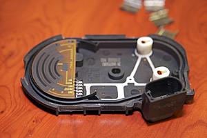
Lid exposing position potentiomitor and motor power sockets.

In the closed position.
Open position.

Cog removed, Magnet installed. In open position.
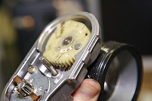
Closed position.
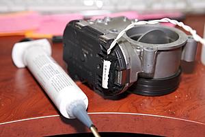
Goo added to Magnet.
Checking clearance.
Open and clearing.
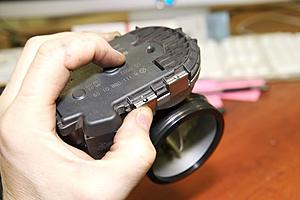
Install cover and snap clips back on.
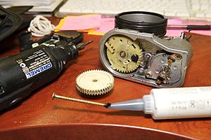
I closed the valve and positioned the reed switch so that it triggered right on the border of fully shut
then tacked the switch with Super glue then with Loctite silicone.
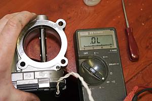
Continuity test. Open circuit.
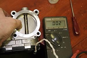
Continuity, Closed circuit... Ahh... Beautiful!
All done!
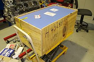
Box from Ebay.

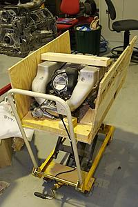
Surprise! one cheep Charger assembly... Cool!

Top condition.
Bum shot. To bad Victors T/B wasn't stuck on here... Dam!
More Later...
There's been much chatter about the super charger by-pass throttle body being open or shut at different times making us paranoid about whether or not we're losing power.
To date... I've never seen a solution that can indicate in real time if this little T/B bludger is open or shut.
I suppose you could shove a stick up there and feel around but it could damage the charger... now we don't want to do that now do we! So I have a more simple solution... stick a magnet inside the by-pass so when the butterfly valve is shut it triggers a normally open reed switch contact closed where you can hook it up to a LED inside the cockpit.
See the following shots on how it was done.
I sourced the reed switch from a Burglar Alarm supply joint. The magnet and reed switch was stuck on with Loctite silicone. A Dremel was used to make a hole in the Butterfly cog. The photos are fairly self explanatory. I'm also going to add the LED to the boost indicator so can I see it all in one spot.
Was checking out Ebay recently and found the induction system of an E55 for 2k USD or landed to my door in Australia for $2850 Ausie Bux which I think is a bargain for a spare charger with all the bells and whistles... See photos... You never know what you'll find. Mmmm SLR Inter-coolers..... "SEARCH"

Engine mounts added and ready for next step...
Bypass Throttle Body. (note: This was off an 03 model, I know there are some that are covered in rubber)
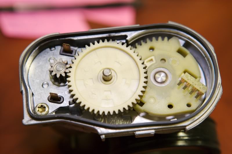
Lid off, just remove the clips that snap off.
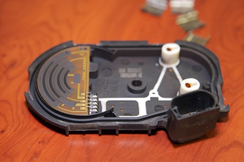
Lid exposing position potentiomitor and motor power sockets.
In the closed position.

Open position.
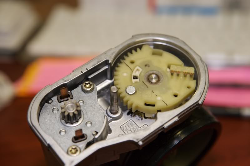
Cog removed, Magnet installed. In open position.

Closed position.

Goo added to Magnet.
Checking clearance.
Open and clearing.

Install cover and snap clips back on.
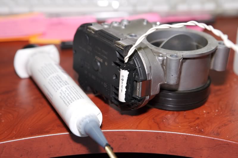
I closed the valve and positioned the reed switch so that it triggered right on the border of fully shut
then tacked the switch with Super glue then with Loctite silicone.
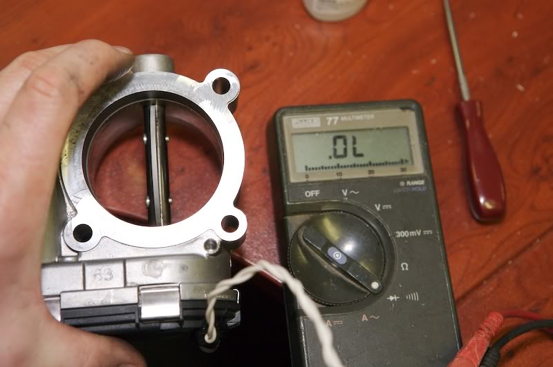
Continuity test. Open circuit.

Continuity, Closed circuit... Ahh... Beautiful!
All done!
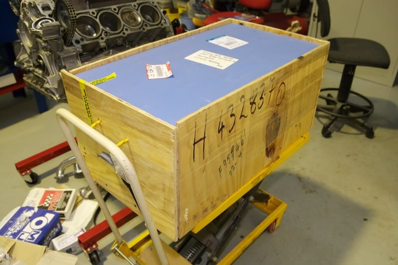
Box from Ebay.
Surprise! one cheep Charger assembly... Cool!
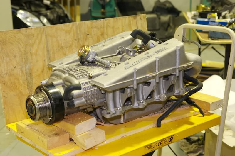
Top condition.
Bum shot. To bad Victors T/B wasn't stuck on here... Dam!
More Later...
Last edited by Finny; 05-10-2007 at 10:02 AM.
05-10-2007, 10:51 AM
#68
MBWorld Fanatic!
Join Date: Oct 2006
Location: Caribbean/Florida/Colorado
Posts: 3,642
Likes: 0
Received 11 Likes
on
11 Posts
E-ZGO 53hp., 1999 E 430 sport, 2004 E 55, 2008 Tahoe LTZ on 24"s
Excellent post, Have you been reading my mind / old posts. Any way the bypass info is real important. I see the next big step to be much like the larger diesel engines. Goes like this Turbo charger to after cooler to supercharger to inercooler. The bottom end 1200-4500 is on the supercharger then as the turbo comes on the by pass opens, bringing on turbo boost from 4500-6000 and that bypass valve and the control of it is paramount, as it allows greater boost at the high end and reduces the approx 32HP to drive the S/C. Thanks for taking the time to post all the great pics and commentary. You are so on the right track.
05-10-2007, 11:32 AM
#69
Banned
Join Date: May 2004
Location: Richmond Hill, Ontario
Posts: 3,797
Likes: 0
Received 2 Likes
on
2 Posts
2003 E55 AMG
Very nice Finny!!!! That is one definitive way of getting some answers.
What would it take to get you to leave Aussie land and come move to the nice cold north?? Would love to have you as a neighbour over here in Toronto.. Just think of all the mad things we could do!!
What would it take to get you to leave Aussie land and come move to the nice cold north??
Would love to have you as a neighbour over here in Toronto.. Just think of all the mad things we could do!!
05-10-2007, 12:27 PM
#70
MBWorld Fanatic!

Join Date: Apr 2005
Location: Brisbane, Australia
Posts: 1,117
Likes: 0
Received 0 Likes
on
0 Posts
2003 E55
Great stuff!
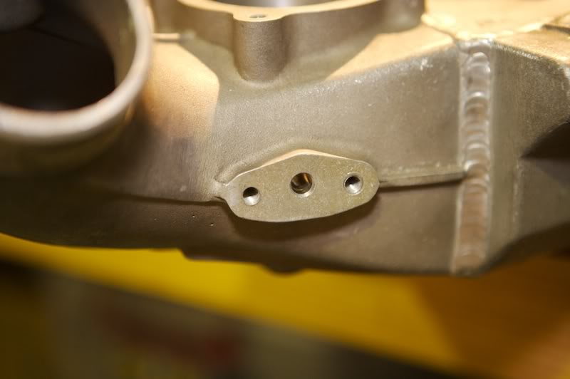
Finny, can you show us where the bypass throttle valve is attached to the engine?
I assume it's wired to the ECU. What happens if its disconnected? Is it open or closed? I suppose your investigations will show us under what driving conditions its open and closed.
Finny, can you show us where the bypass throttle valve is attached to the engine?
I assume it's wired to the ECU. What happens if its disconnected? Is it open or closed? I suppose your investigations will show us under what driving conditions its open and closed.
05-10-2007, 12:36 PM
#71
MBWorld Fanatic!
What are those two things lying on top of the S/C (in the top condition picture) looks like a vacuum valves or something?
05-11-2007, 05:42 AM
#72
Super Member
Thread Starter
Great stuff!
Finny, can you show us where the bypass throttle valve is attached to the engine?
I assume it's wired to the ECU. What happens if its disconnected? Is it open or closed? I suppose your investigations will show us under what driving conditions its open and closed.
Finny, can you show us where the bypass throttle valve is attached to the engine?
I assume it's wired to the ECU. What happens if its disconnected? Is it open or closed? I suppose your investigations will show us under what driving conditions its open and closed.
I wouldn't suggest disconnecting the bypass as it's fully open when disengaged. Would be a good party trick If you really wanted to annoy someone though.
If I discover that there was premature power loss due to bypass activation, I'll then endeavor to correct the problem if any.
Well I'm doing my best to venture down that way this year, much beaver down that way?
05-11-2007, 03:03 PM
#73
Super Member
Thread Starter
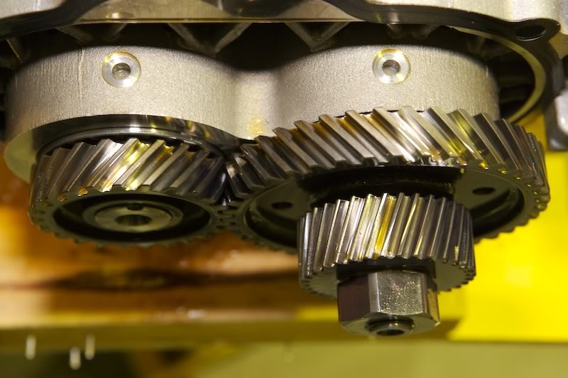
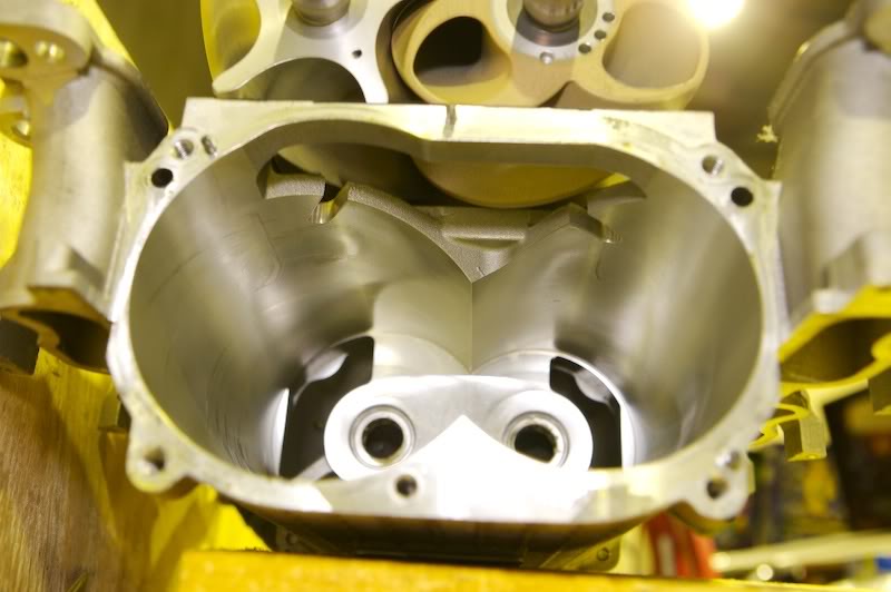
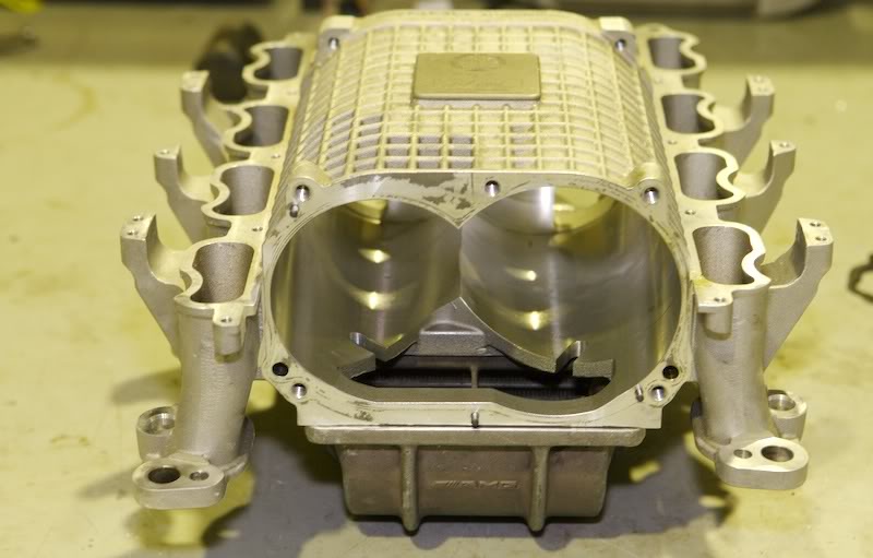
You've just spent a stack of coin porting your heads to flow all that extra air and you wonder... am I maximizing my investment in the heads only to be choked by supercharger apparatus?
Well there is a little more you can do to improve the induction. Although were fighting over crumbs here, I think that every bit of effort in aiding the flow helps. Read on for my 2 cents worth...
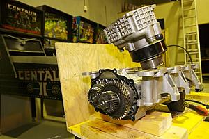
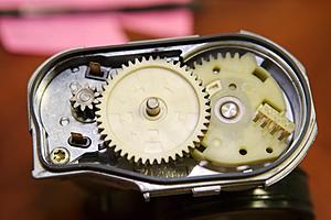
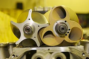
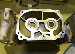
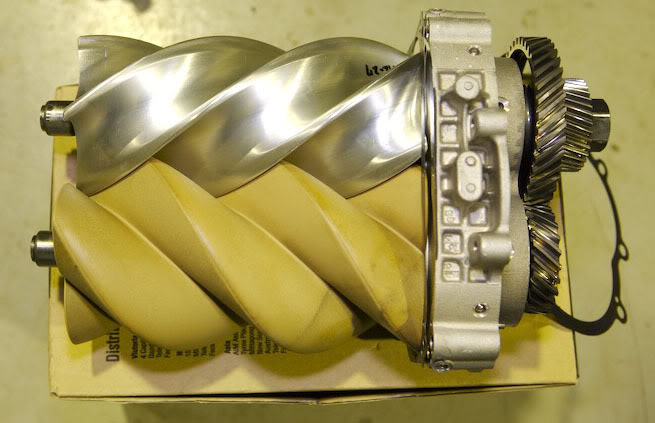
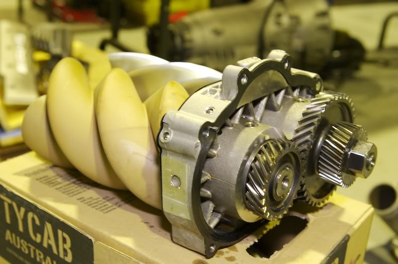
Lets pop off the lid and have a look inside. That freekin clutch is heavy!
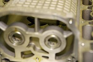
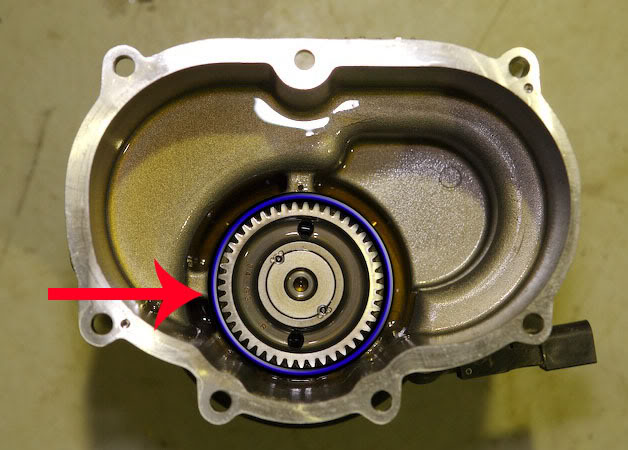
Nice helical gears. The one on the right is interchangeable. Mmmm Interesting.
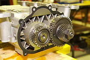
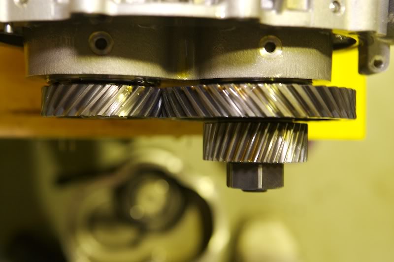
Lets have a look in here too.
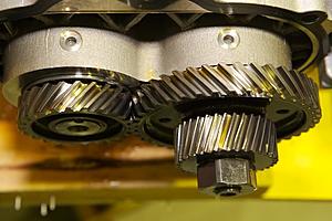
Helical macro shots.

This one has been pinned to stay.
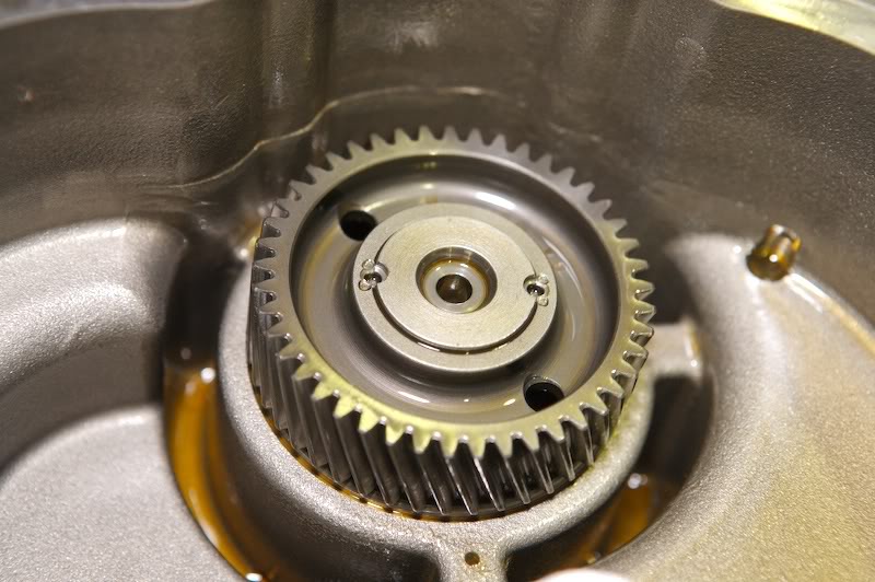
Just speculating here... Maybe the SLR's gear is larger and the one on the main side smaller as there is more room around the case for improvement?
Interesting though...
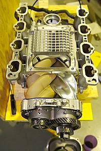
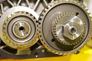
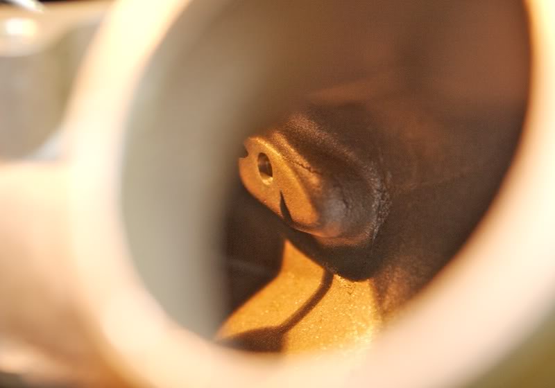
Inlet side of rooters
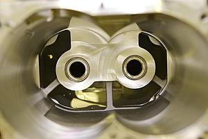
Inlet side of charger. I haven't investigated this part yet but I reckon more meat can come off here.
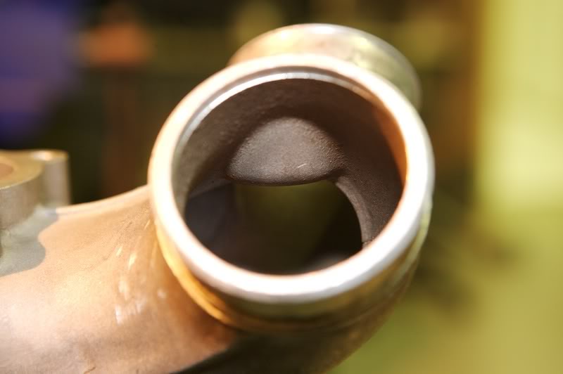
To the top is the outlet section. Compression occurs down that barrel.
I don't think a bee's dick will fit between there?
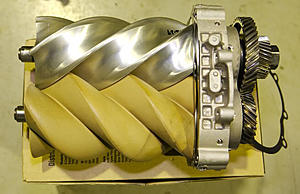
Outside of inlet. Yeah... more meat can come off here!
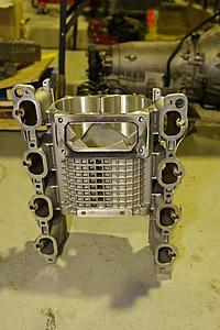
With all the bits off it's surprisingly light.
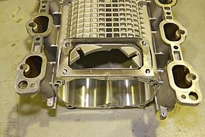
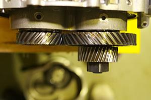
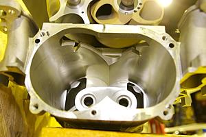
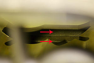
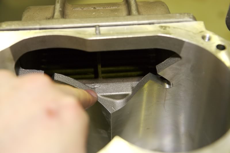
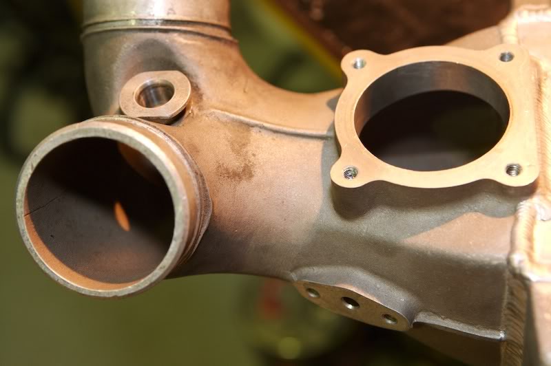
The next 3 shots show where some flow improvement can be made. The lower outlet lip can have a shave to help flow.
Here is one of the biggest offenders. See that extra meat around the gasket.. Chop Chop.
Next victim... I'm going to shave this too so it matches the out let manifold. Cutting back too much this way is counter
productive because the compression occurs in the barrel above. I'm just going to remove that rectangular bit sticking
out to match the manifold.
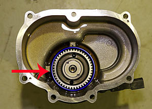
Looking from the rear in. The opposite side of that rectangular bit.
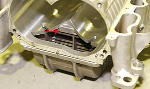
Arrow above is the S/C case and the one just below is the outlet manifold. A big Chop Chop here too! 2 or 3mm along this edge.
How they sit together.
Well there is a little more you can do to improve the induction. Although were fighting over crumbs here, I think that every bit of effort in aiding the flow helps. Read on for my 2 cents worth...

Lets pop off the lid and have a look inside. That freekin clutch is heavy!

Nice helical gears. The one on the right is interchangeable. Mmmm Interesting.

Lets have a look in here too.
Helical macro shots.

This one has been pinned to stay.
Just speculating here... Maybe the SLR's gear is larger and the one on the main side smaller as there is more room around the case for improvement?
Interesting though...

Inlet side of rooters

Inlet side of charger. I haven't investigated this part yet but I reckon more meat can come off here.
To the top is the outlet section. Compression occurs down that barrel.
I don't think a bee's dick will fit between there?

Outside of inlet. Yeah... more meat can come off here!

With all the bits off it's surprisingly light.

The next 3 shots show where some flow improvement can be made. The lower outlet lip can have a shave to help flow.

Here is one of the biggest offenders. See that extra meat around the gasket.. Chop Chop.

Next victim... I'm going to shave this too so it matches the out let manifold. Cutting back too much this way is counter
productive because the compression occurs in the barrel above. I'm just going to remove that rectangular bit sticking
out to match the manifold.

Looking from the rear in. The opposite side of that rectangular bit.

Arrow above is the S/C case and the one just below is the outlet manifold. A big Chop Chop here too! 2 or 3mm along this edge.

How they sit together.
Last edited by Finny; 05-11-2007 at 03:12 PM.
05-11-2007, 03:06 PM
#74
Super Member
Thread Starter
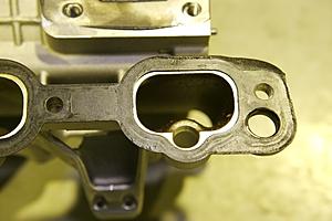
Chop Chop here!

And here...
Output side.
This is where the positive air pressure out sensor is mounted.
I can't believe the size of that lug mount inside.. Chop Chop!

This is the base of the air temperature out sensors home. Another unnecessary obstruction... Chop Chop!

I think a hole saw and a die grinder should do the trick here.
The other side. Once this is gone, there should be a little more flow gained here.
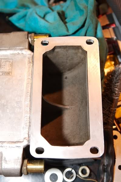
A little bit of work to be done here too. The intercooler core, the worst offender of all, Chop Chop Chop!!!!
More to come soon...
05-11-2007, 03:38 PM
#75
MBWorld Fanatic!
Join Date: Oct 2006
Location: Caribbean/Florida/Colorado
Posts: 3,642
Likes: 0
Received 11 Likes
on
11 Posts
E-ZGO 53hp., 1999 E 430 sport, 2004 E 55, 2008 Tahoe LTZ on 24"s
Thanks Finny,
You should be on Speed Channel, I can see it now "THE FINNY SHOW"
BTW that S/C is clean, is that the E-bay one?
You should be on Speed Channel, I can see it now "THE FINNY SHOW"
BTW that S/C is clean, is that the E-bay one?


