When you click on links to various merchants on this site and make a purchase, this can result in this site earning a commission. Affiliate programs and affiliations include, but are not limited to, the eBay Partner Network.
Since I plan on putting slicks on my car and getting plenty of track time, I decided to proactively reinforce the rear subframe bolts to avoid having them ripped out of the body, as has happened to numerous others.
Since I’m doing this BEFORE it becomes a problem, it’s a pretty straight forward process. Basically, I’m removing the old bolts, drilling out the body mount threads, and installing new through-bolts that are stronger and have washers to spread the load and allow much more torque to be transmitted through the frame without ripping out the mounts.
Tools Required
Wheel Chocks
Floor Jack
Two Jackstands
8” length of 2x4
Lug Wrench
Torque Wrench
10mm Socket
Plastic Fastener Removal Tool
Screwdriver
2” Bi-metal hole saw with pilot bit
Drill
�” or 13mm drill bit
E18 External Torx socket
18mm Box-end wrench
16mm Socket
Fasteners (links are dead; see below)
Marafast ATVT12110175P M12-1.75 x 110mm Cl.12.9 DIN 6921 Frame Bolt, Black Phos. & Oil (Pack of 1; 2 required)
Set the emergency brake and place the wheel chocks in front of the front wheels.
Position the floor jack under the rear differential, with the 2x4 wood block on the pad of the jack IN FRONT OF THE COOLING FINS of the differential. See pic for details. Make sure there is no pressure placed on the cooling fins, as they won’t support the weight of the car.
Place the two jackstands at the frame lift points on either side of the car and lower the jack.
Remove the rear wheels, then remove the rear portion of each fender liner. You’ll need the 10mm socket to remove a few plastic nuts (there are a different number on the passenger and driver’s sides). Locate the plastic rivets and use the tool to remove them (again, there are different numbers on each side of the car). Even after the nuts and rivets are removed, there are a few snap-in points that may require a screwdriver to help you get them disconnected.
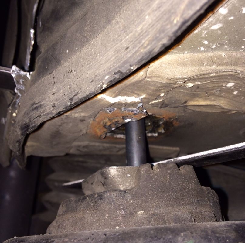
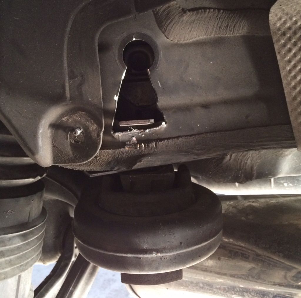
After removing the rear portion of the fender liner, use the hole saw to drill a 2” hole directly below the small existing hole. Placing the pilot bit in the little valley will position the hole perfectly.
Use the E18 external torx socket to remove the existing bolt.
Use either a �” or 13mm drill bit to drill out the old threads. Do this by drilling up from below.
Insert the new bolt up through the mount and into the frame. Secure it with a washer and nut, using the access hole you drilled in step 4. Torque to 110 ft-lb (the nut takes an 18mm wrench, the bolt takes a 16mm socket)
I did not close the holes yet, but I plan on cementing a rubber sheet over them. My original plan was to use a 2” plastic hole plug, but the contours of the sheet metal make it difficult.
Now replace the fender liners and put the tires back on and you’re done. Now go burn some rubber!
Last edited by JoeJErnst; 09-07-2017 at 01:56 PM.
Reason: Added new links for fasteners
Considering the thunk and "walking" rear end under mild acceleration and in the corners I am going to take a stab at this on Sunday. Is it pretty obvious when these bolts give way?
You enhance the bolt-connection of the subframe while weakening the strength of the body!?
And you give rust a chance to attack you body!
I call this crazy!
I actually put a lot of thought into that very notion. My original plan was to weld the nut and washer to the body, and then weld back in the circular piece that I cut out. I don't have a welder, so I saved the cutouts in case I decide to weld them back in later.
Given the current evidence, I made the decision to do this "upgrade" because I feel the danger of ripping the mounts out of the body far outweighs the minor weakening of the structure by drilling a hole in the sheet metal, but I'm not an engineer so that's just my opinion and is not substantiated by any math.
As for the rust issue, like I said above I will be using some RTV silicone to cement a rubber patch over the holes to keep water out. I'll update my original post with pics once I do it.
Considering the thunk and "walking" rear end under mild acceleration and in the corners I am going to take a stab at this on Sunday. Is it pretty obvious when these bolts give way?
Mine was very obvious. One was when I was simply turning right on an on-ramp type thing at ~40 mph. It was a very loud pop. The back right was riding a few inches higher than the rest.
For mine, it was not the bolt that broke. It ripped out of the subframe. OP is just trying to distribute the force over a larger part of the frame to prevent that from happening. I had two pieces of plate steel added to sandwich that part of the frame.
With the bolts no longer being the weakest link, is there any chance of damaging the subframe now?
The bolts aren't always the weakest link. Based on the research I've done (searching for and reading every post on the subject on this site), there are two failure modes: 1) The bolt shears off, and 2) The threaded mounting point rips off.
Scenario 1 is relatively easy to fix; just extract the broken piece of bolt and put in a new one torqued to spec. Scenario 2 is more difficult, because the threaded mounting boss has actually been ripped out of the body. Repairing that means cutting a hole and using a larger flat piece of metal to cover the now gaping hole in the mounting bracket.
I guess it's worth noting that if the MB engineers designed these mounting points to be "break away" then this modification will certainly alter the design. This isn't the type of modification I would make without strong evidence showing the downside of NOT doing it.
I think I'll do the preventative route rather than waiting for a "Denroll" instance. I know I can't 100% prevent it. But I'll check it out tonight and let you guys know. I have had a thunk going over bumps but I figured it was just a shock absorber. My rear end doesn't sit higher (actually lower) than the front when leveled. Has anybody welded in plates and boxed in the subframe mount? I will look into that. It's not like weight is a issue with these cars lol
Toe links such as Shardul offers will greatly reduce the load on the sub frame bolts. I do not know of any sub frame bolt failures on toe link equipped cars.
Toe links such as Shardul offers will greatly reduce the load on the sub frame bolts. I do not know of any sub frame bolt failures on toe link equipped cars.
Can you elaborate? I don't understand the physics behind this statement.
Can you elaborate? I don't understand the physics behind this statement.
I am assuming the OEM rubber flexes under load and thus relys on the subframe bolts to keep everything inplace. UDP links are solid (no rubber) and keep the load off the sub frame bolts. No flex = no load
I've been doing research on this aswell.. luckily theres a lot of good info nowadays regarding this. Def going to go with the OP's way as long as everything is still fine.
The hole to be drilled needs to be just as big that the nut and washer will fit through? So theres nothng else to see there?
14 E63, 05 E55, 03 Evo 8, 08 F250, 06 R6R, 92 Talon TSI, and instability
Originally Posted by JoeJErnst
As for the rust issue, like I said above I will be using some RTV silicone to cement a rubber patch over the holes to keep water out. I'll update my original post with pics once I do it.
That's probably the best method now that you've done this for if you ever need to drop the subframe for any reason.
I've been doing research on this aswell.. luckily theres a lot of good info nowadays regarding this. Def going to go with the OP's way as long as everything is still fine.
The hole to be drilled needs to be just as big that the nut and washer will fit through? So theres nothng else to see there?
That's right. I used a 35mm washer, which means I could have gone with a smaller hole saw, but I didn't know exactly what was hiding behind the sheet metal. Also keep in mind that you'll need to be able to get a wrench on the nut.
00 MB ML55, 91 Toyota Supra Turbo(sold), 06 E500(gone), 03 BMW M3
Originally Posted by AgSilver
Toe links such as Shardul offers will greatly reduce the load on the sub frame bolts. I do not know of any sub frame bolt failures on toe link equipped cars.
Originally Posted by shardul
well said. i was waiting for someone to say it.
Originally Posted by 2000UZJ
I am assuming the OEM rubber flexes under load and thus relys on the subframe bolts to keep everything inplace. UDP links are solid (no rubber) and keep the load off the sub frame bolts. No flex = no load
Correct me if I am wrong Shardul.
So we could either cut holes that may or may not rust in the future, or install upgraded toe links... guess I need to add another part to the list I need to purchase
So we could either cut holes that may or may not rust in the future, or install upgraded toe links... guess I need to add another part to the list I need to purchase
Replacing the bolts with Joe's method and UDP links would be the ultimate reinforcement. Your best judgement should determine whether you "need" to do this. However it's a nice mod and a little confidence booster every time you put your foot down.
Climate is a huge factor. Mag chloride + pot holes = a subframe bolt that has seen many stretch and compound cycles, as well as rust/oxidation. Probably best to use Joe's sandwich method.
The roads I drive on don't have pot holes. I also don't see any type of salt, snow, etc. My bolts were torqued down and intact. I am still replacing them this winter though.

 10-08-2014, 03:13 AM