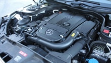
Mercedes-Benz E-Class: How to Replace Starter
Changing the starter on a Mercedes-Benz E-Class is a challenging job, but will save you hundreds if you can do it yourself. Learn how to replace it here.
This article applies to the Mercedes-Benz E-Class (2002-2009).
Every time the key is turned to crank in the ignition switch, the starter transfers the electrical energy stored in the battery to mechanical energy. This mechanical energy is used to rotate the engine until it reaches an idle. Starters can fail in a multiple number of ways, one being a mechanical bind that causes the gear in the starter to jam and possibly damage the ring gear/flex plate. Another failure is electrical. This failure can be caused by a broken power or ground wire leading to and away from the starter or the starter itself. Diagnosis of the starting system is the best way to determine what is at fault.
Materials Needed
- 10mm sockets
- 10mm and 13mm stubby wrenches
- e12 and e14 (external Torx) sockets
- Floor jack
- Jack stands
- Wheel chocks
- Safety glasses
- Torque wrench
- Flat head screwdriver
- T45 Torx socket (depending on the model)
- Penetrating oil
- 12" 3/8" or 1/2" extension
- 3/8" or 1/2" swivel
- 9 volt radio code memory saver
- 27mm long socket
The procedures differ between the six (v6) and eight (v8) cylinder engines. When necessary, instructions for the 5.5 liter v8 and 5.0 liter v8 will be color coded.
- v6 = black
- (r)5.5 liter v8 = red (r)
- (b)5.0 liter v8 = blue (b)
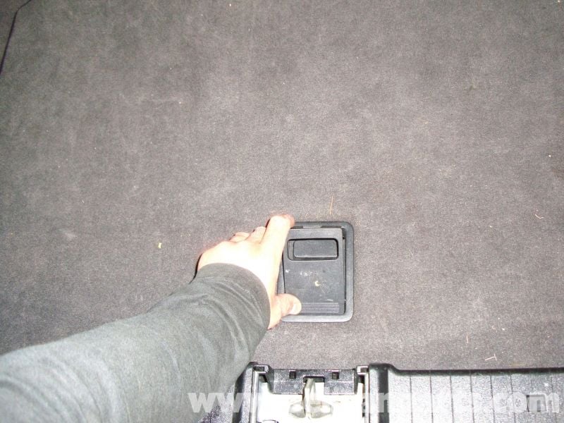
Step 1 – Disconnect the negative battery cable
First connect the memory saver to the power outlet near the radio.
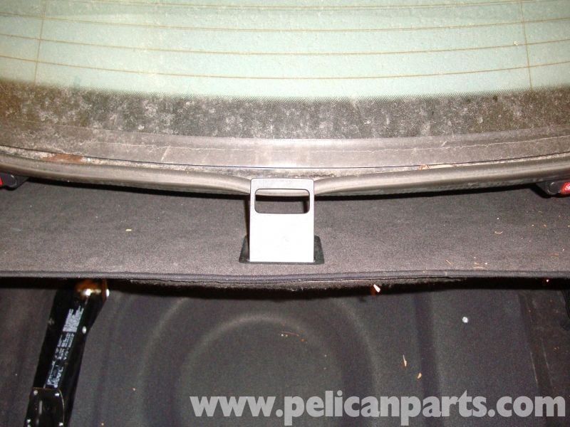
Raise the trunk cover using the clasp.
The clasp will hook onto the trunk seal.
Note
If your trunk seal is in poor condition, then the seal may become detached from the trunk.
Remove the carpet panel.

Disconnect the negative battery terminal.
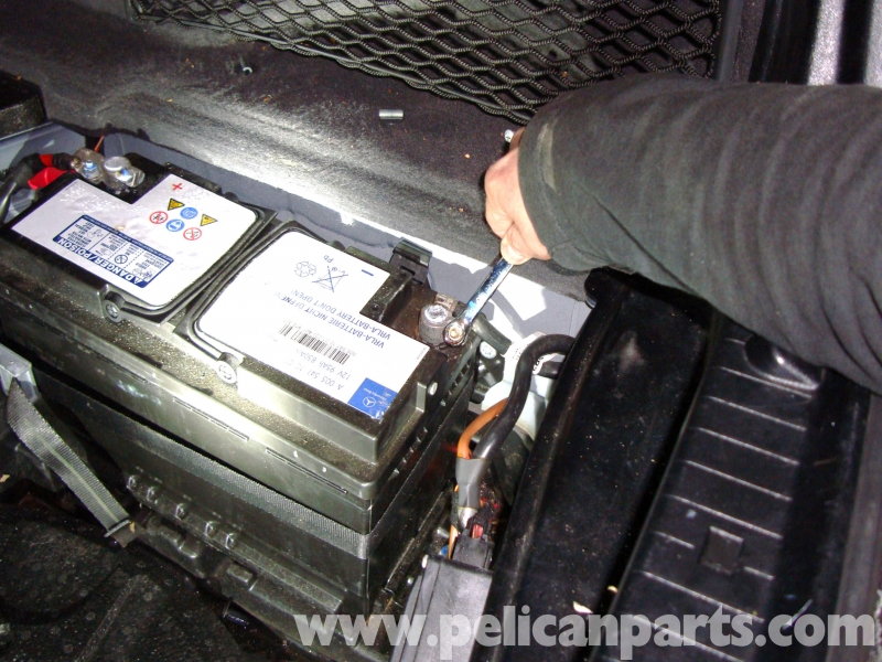
Once disconnected, insulate the terminal to eliminate the chance of connection to the battery. This can be done by wrapping it with electrical tape.
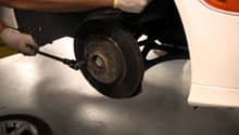
Step 2 – Raise and support the vehicle
Apply the parking brake. Locate the jack points on each side of the vehicle.

With a jack, raise the vehicle on the right front jack pad high enough to position a jack stand under the right rear jack pad. It is best to raise the vehicle in increments from spot to spot. This eliminates the chance of the vehicle moving on the jack stands. Move the jack to the rear differential (Figure 7) and raise the vehicle high enough with a block of wood to fit a jack stand under the left rear jack pad. Move the jack to the left front jack pad and raise the vehicle again to place a jack stand under the right front jack pad. Now use the oil pan (Figure 8) to raise the left front jack pad high enough for a jack stand to fit under it.
The jack pads may need to be installed on the vehicle, typically requiring one bolt to secure it to the body.
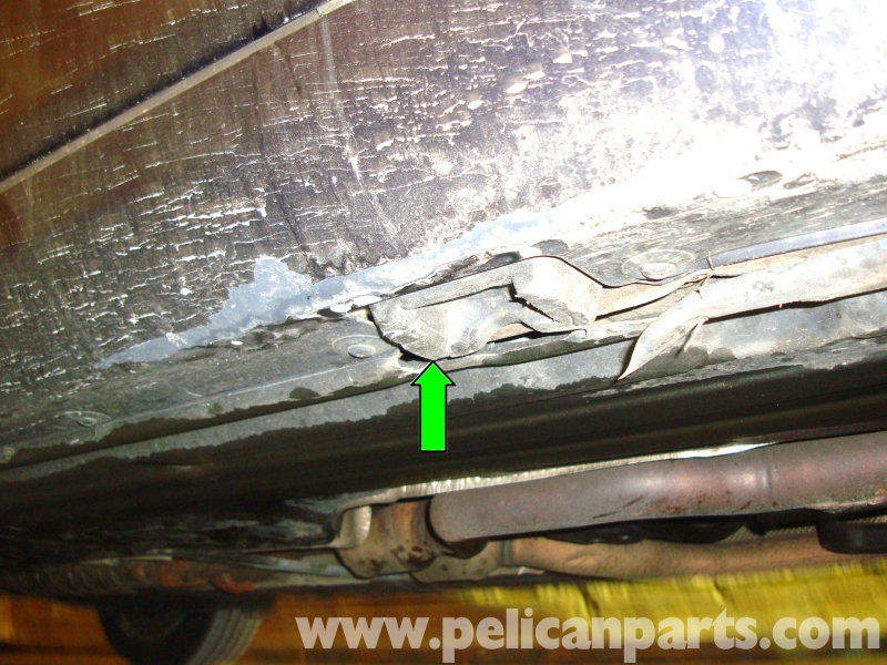
Figure 6. One of the four jack pads. 
Figure 7. Position the jack to allow the block of wood to contact the rear differential. 
Figure 8. Position the jack to allow the block of wood to contact the bottom of the oil pan.
Pro Tip
Depending on the amount of space you like, only the front of the vehicle can be raised.
Step 3 – Remove the engine splash shields
Loosen the 8mm fasteners in the order shown in Figures 9-15. The fasteners are indicated by green arrows.
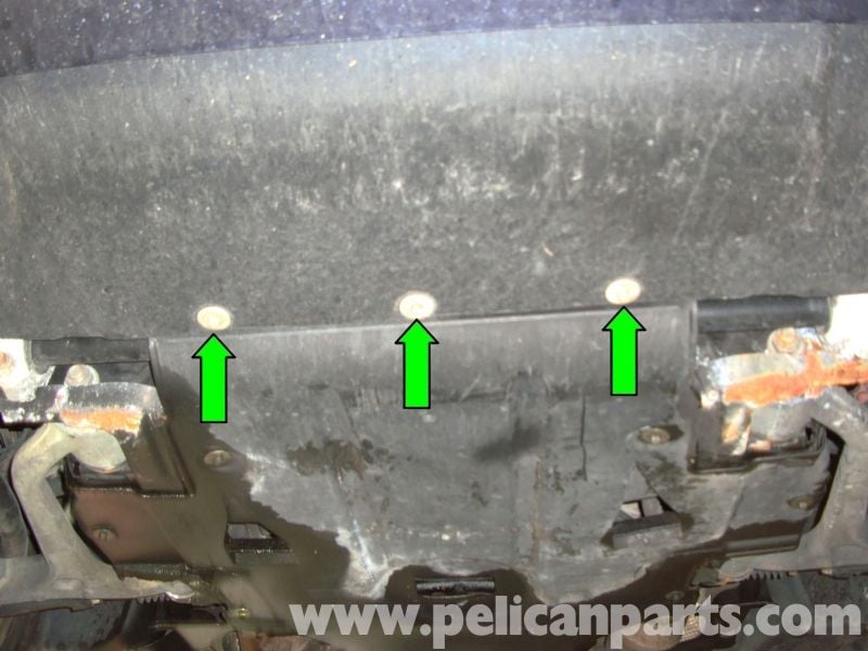
Figure 9. These fasteners are located on the bottom of the front bumper. 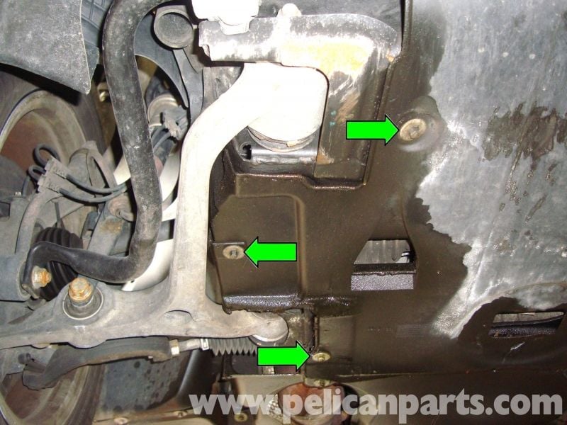
Figure 10. Remove the three fasteners located by the right lower control arm. 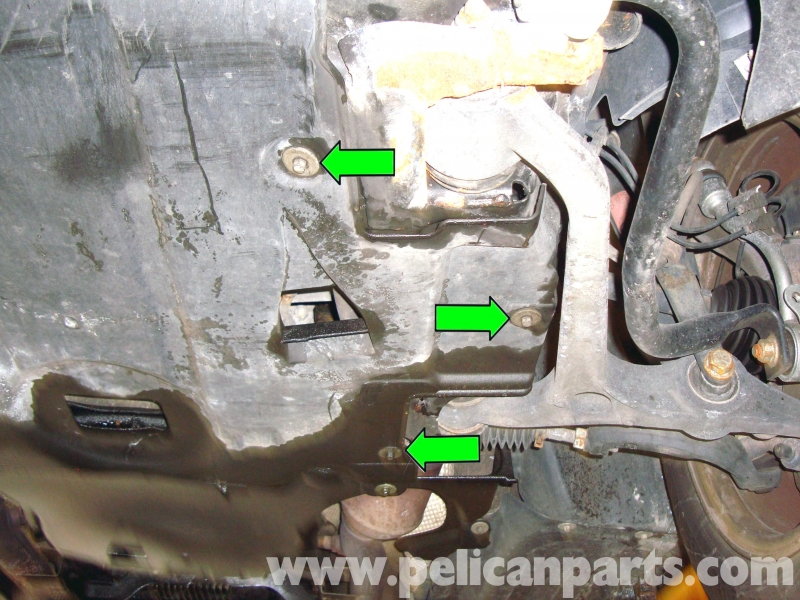
Figure 11. Remove the three fasteners located by the left lower control arm.
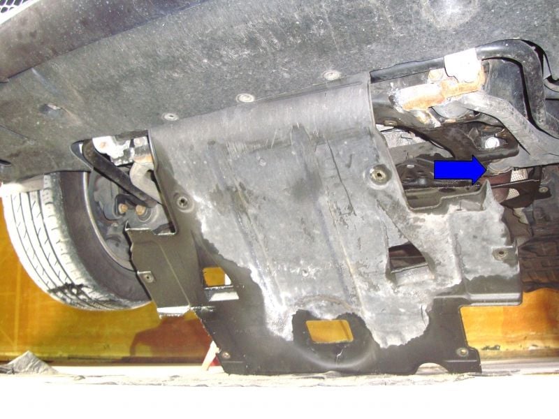
Figure 12. Lower the splash shield while pulling it towards the rear of the car. 
Figure 13. Remove the two fasteners located by the left exhaust pipe. 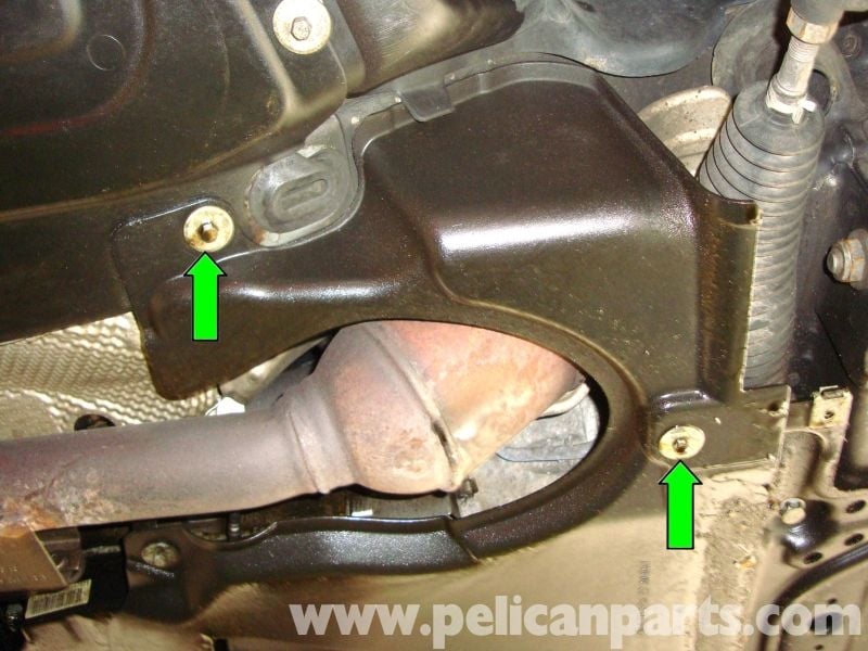
Figure 14. Remove the two fasteners located by the right exhaust pipe. 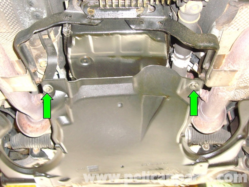
Figure 15. Remove the two fasteners located below the transmission fluid pan.
Pro Tip
Now is the time to clean the engine/transmission and inspect for fluid leaks. A scrub brush mixed with an engine degreaser and water works well.
Step 4 – Remove the front right exhaust pipe
If your vehicle has high mileage or appears to be rusty, then it's recommended to spray the exhaust bolts with penetrating oil to reduce the risk of broken bolts.
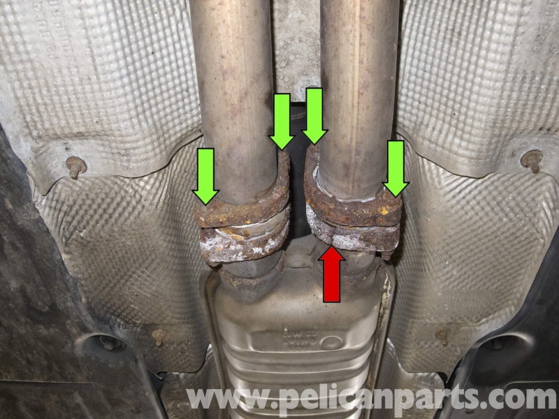
First, disconnect the exhaust at the four 13mm fasteners located in front of the muffler.
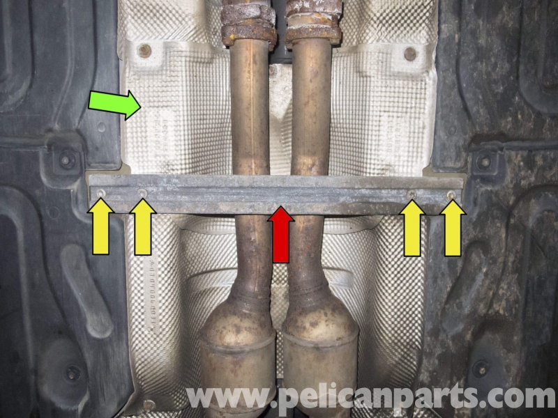
Then, remove the support connecting each side of the exhaust tunnel. Four T45 Torx bolts hold it in place.
The oxygen sensor connectors need to be disconnected next.
There are two 13mm bolts holding the exhaust to the exhaust manifolds on both sides of the engine. Start at the right side first.
Then, the left. The rear bolt needs to be accessed from the side as shown in the left image of Figure 19. The front bolt needs to be accessed from the front on vehicles with 4MATIC (all wheel drive) as shown in the right image of Figure 19.
The exhaust center support wraps around the transmission fluid pan. There are four 12mm nuts holding it to the exhaust. Two 13mm bolts hold the center support to the transmission. The insulating plate will also need to be removed.
Finally, pull the exhaust away from the manifolds.
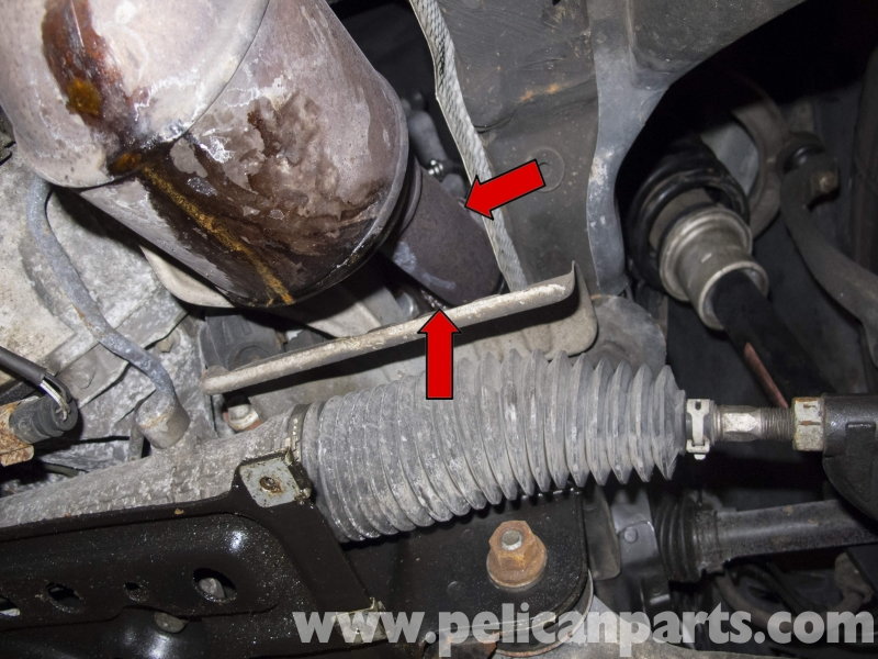
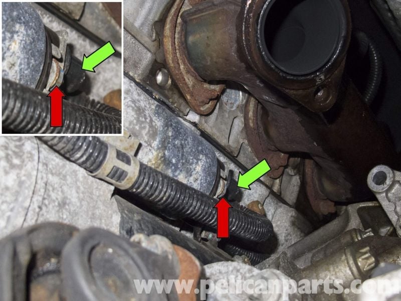
(r) For 5.5 liter (V8) engine owners the next step is to remove the bracket that holds a hydraulic line above the starter. You will also have to pry the metal clamp located around the wiring harness near the starter. Do this by prying the clamp towards the front of the engine.
(b) For the 5.0 liter engine, remove the two wires connected to the starter solenoid.
(Related Article: Mercedes-Benz E-Class: How to Replace Oxygen Sensor - MBWorld.org)
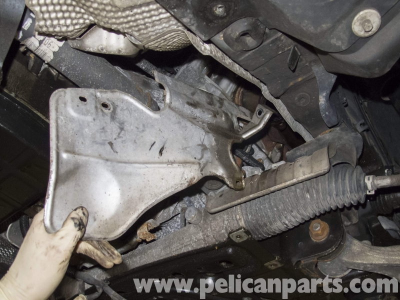
Step 5 – Remove the heat shield
Remove the E12 external Torx fastener, and then the two 10mm bolts holding the heat shield to the engine.
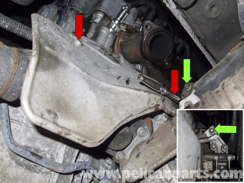
Remove it from the vehicle.
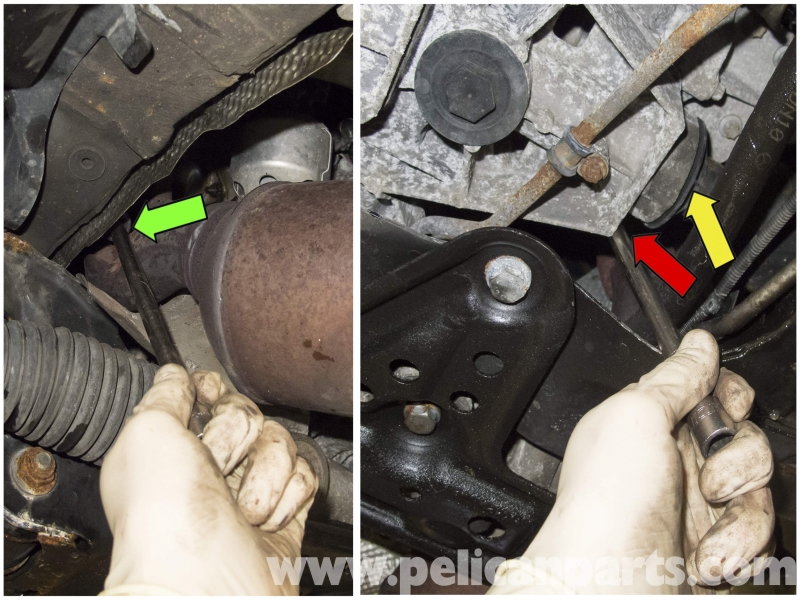
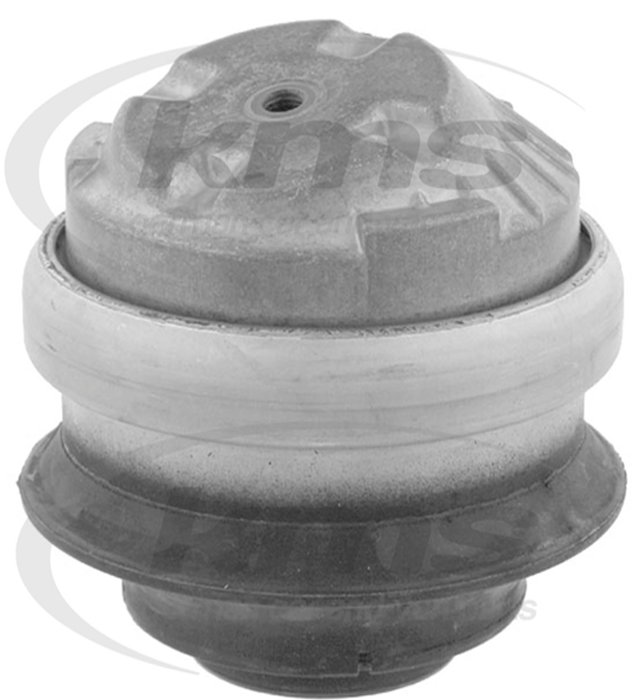
(r) For the 5.5 liter engine, the engine mount will need to be moved to gain access to the starter. To remove it completely, the exhaust system will also need to be removed.
(b)The 5.0 liter engine requires the removal of the bolt located on the right engine mount. The engine will need to be suspended, either by an engine hoist from the top or a floor jack from the bottom. A piece of wood should be used to prevent the oil pan from being damaged when the jack is contacting it.
Step 6 – Disconnect the wires attached to the starter
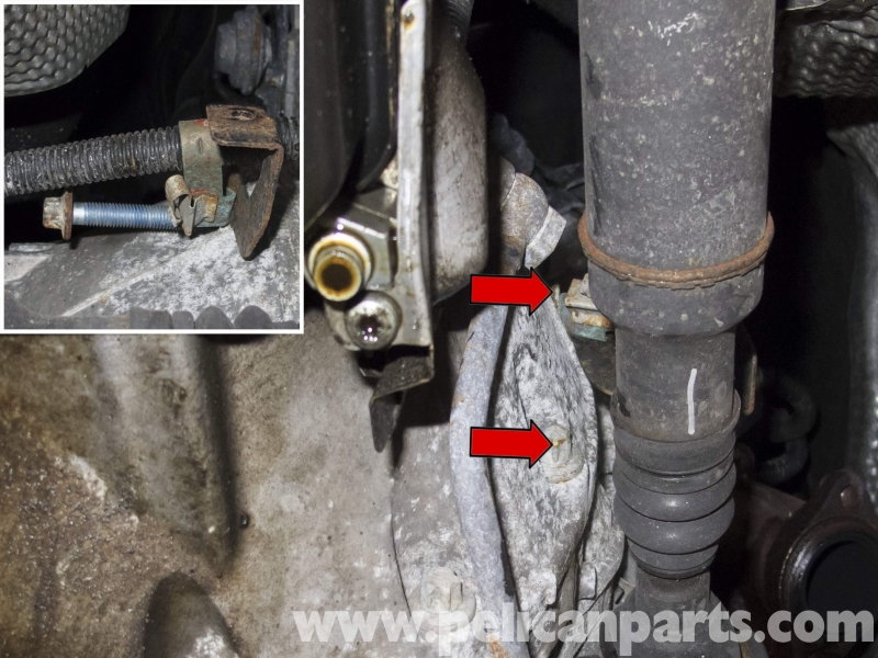
First, remove the 13mm nut holding the battery cable to the back of the starter, then the 10mm nut in front of it. The plastic cap over the 13mm nut pops out of place.
The battery cable runs back towards the transmission and has two mounting tabs that will be removed. The first must be pulled away from the slot and pried open. The second is attached with a starter mounting bolt and will be detached later.
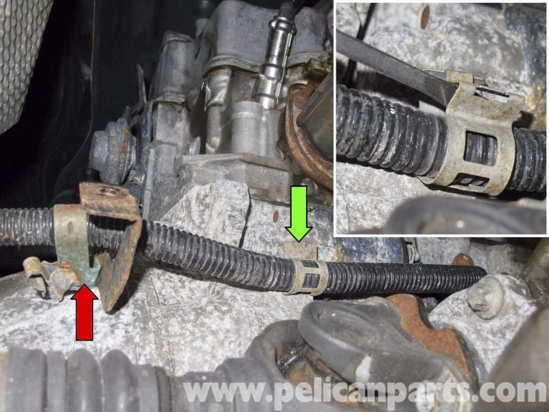
Once the mounting tab is opened, pull up on the battery cable to remove it.
(b) Now is the time to remove the cables from the starter for the 5.5 Liter. This is similar to the (v6).
Step 7 – Remove the fasteners holding the starter
There are two 14mm external Torx bolts holding the starter to the crankcase. When the top bolt is removed, the rear mounting tab holding the battery cable will also be removed.
Remove the starter from the vehicle by first tilting it up...
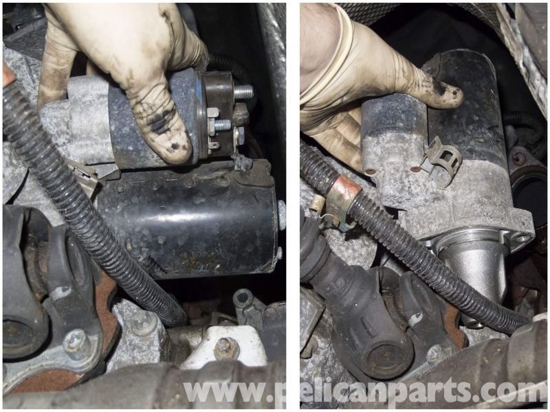
...then by wiggling it down and out.
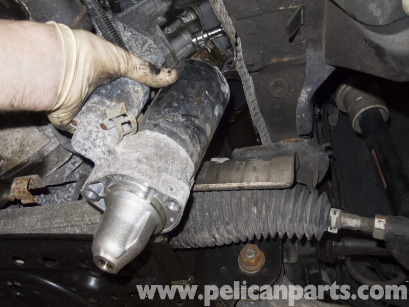
(r)The 5.5 liter engine has six bolts holding the starter to the crankcase. You will need to pull it down and out to remove it from the vehicle.
(b)The 5.0 liter engine has three bolts holding the starter to the crankcase. Pull the starter towards the side to remove it from the vehicle.
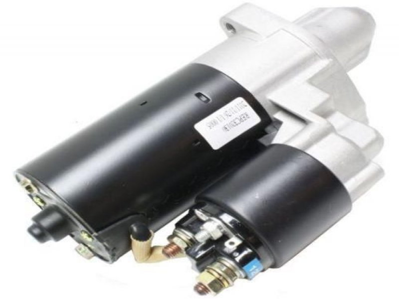
Step 8 – Inspect the starter and ring gear/flex plate for damage
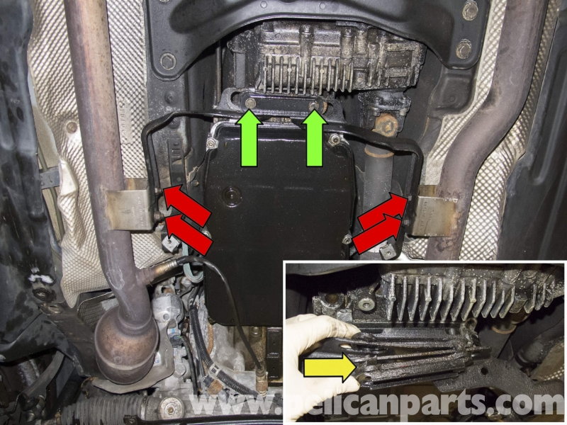
This applies to all engines. Inspect the gear teeth on the starter for damage (chips, bent teeth). Do the same for the ring gear/flex plate. It can be seen through the hole the starter was pulled out from. Rotate the engine clockwise using a 27mm long socket connected to the crankshaft pulley to examine the entire gear.
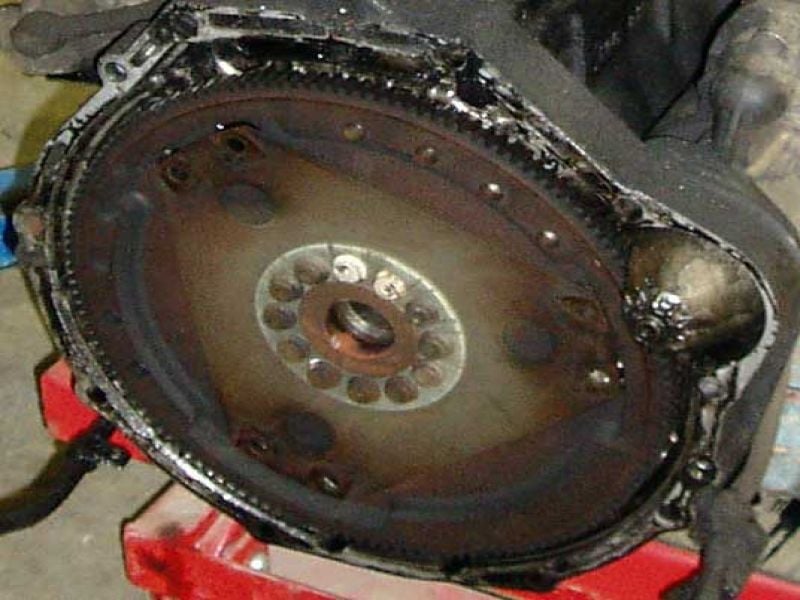
Figure 31. An example of a starter contacting a ring gear. 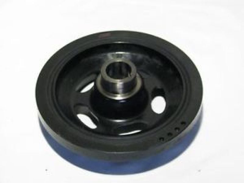
Figure 32. An image of the crank pulley.
Step 9 – Complete the starter installation
- Install in the reverse order. Do not over tighten the nuts on the solenoid as they require only 5-10 ft-lbs. The starter to crankcase bolts require 30 ft-lbs.
- There is a normalizing procedure to program the electrical system when the battery is disconnected. To normalize the power windows, hold the switch in the up position for three seconds.
- Hold the tilting roof switch open for three seconds once it reaches the mechanical stop.
- To reset the ESP (steering angle sensor) start the vehicle and turn the wheel from lock to lock. Return the wheel to the center position.
Related Discussion and Site
- Red Battery Message Visit Workshop - MBWorld.org
- Mercedes W211 6-Cylinder Engine Starter Replacement - Pelicanparts.com