
DIY I-Pod Install

 10-18-2008 | 10:59 PM
#1
Thread Starter
MBWorld Fanatic!
Joined: Oct 2006
Posts: 3,642
Likes: 11
From: Caribbean/Florida/Colorado
E-ZGO 53hp., 1999 E 430 sport, 2004 E 55, 2008 Tahoe LTZ on 24"s
DIY I-Pod Install
Well let me start out by thanking AMGfan. His major audio/video/nav upgrade made his MB I-Pod integration kit available. I feel that I got more than a fair deal, so to pass along the goodwill, here is a DIY, for anyone interested in this factory option.
This is a pic of all the components in the kit and I-Pod cradle.
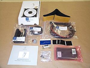
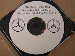
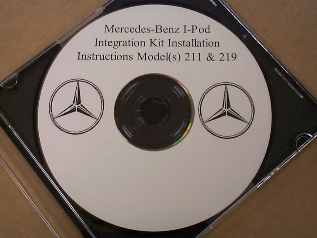
This is the install CD, it is a must have to do this install. It contains SDS Star programing information and other important warnings and tips.
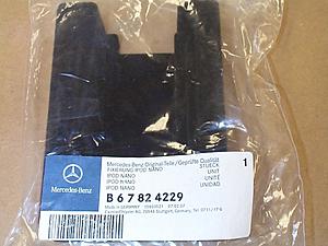
This is the cradle for the I-Pod it holds most, I'll be using 80 G Classic. This is not included in the kit and must be purchased separately.
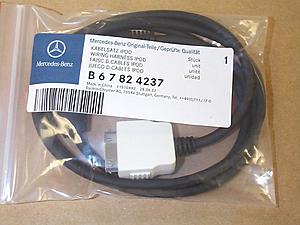
The cable that runs from interface to I-Pod.
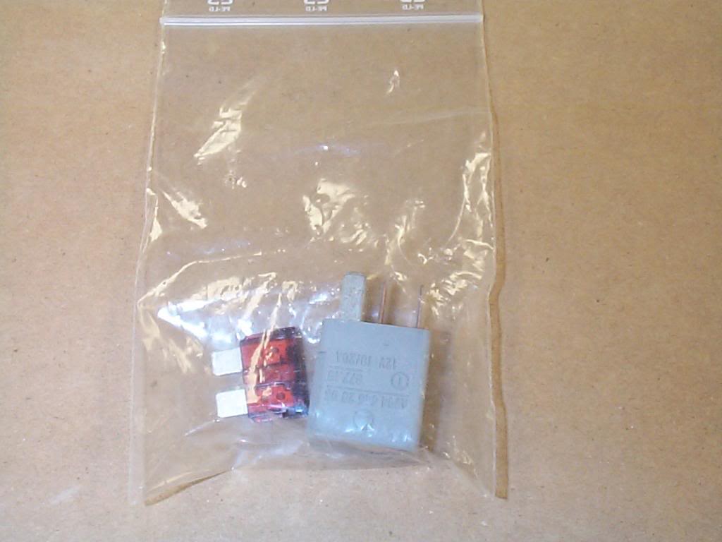
The fuse and power relay.

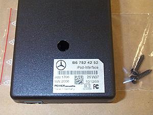
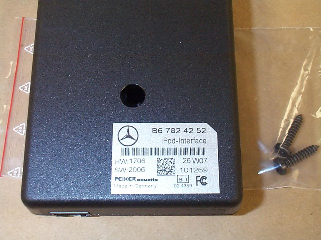
I-Pod interface.
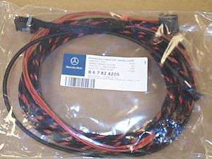
Wire loom, runs from trunk to command head unit.
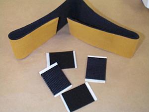
Velcro to mount interface and felt to cover wires in trunk.
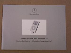
Operators manual.
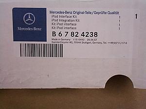
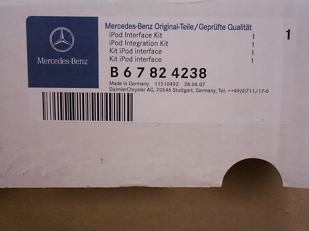
The Kit part number.
This is a pic of all the components in the kit and I-Pod cradle.

This is the install CD, it is a must have to do this install. It contains SDS Star programing information and other important warnings and tips.
This is the cradle for the I-Pod it holds most, I'll be using 80 G Classic. This is not included in the kit and must be purchased separately.

The cable that runs from interface to I-Pod.

The fuse and power relay.
I-Pod interface.
Wire loom, runs from trunk to command head unit.

Velcro to mount interface and felt to cover wires in trunk.

Operators manual.
The Kit part number.
Last edited by Yacht Master; 10-19-2008 at 08:03 PM.
10-18-2008 | 11:08 PM
#2
Thread Starter
MBWorld Fanatic!
Joined: Oct 2006
Posts: 3,642
Likes: 11
From: Caribbean/Florida/Colorado
E-ZGO 53hp., 1999 E 430 sport, 2004 E 55, 2008 Tahoe LTZ on 24"s
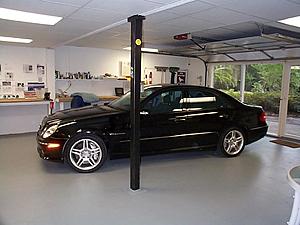
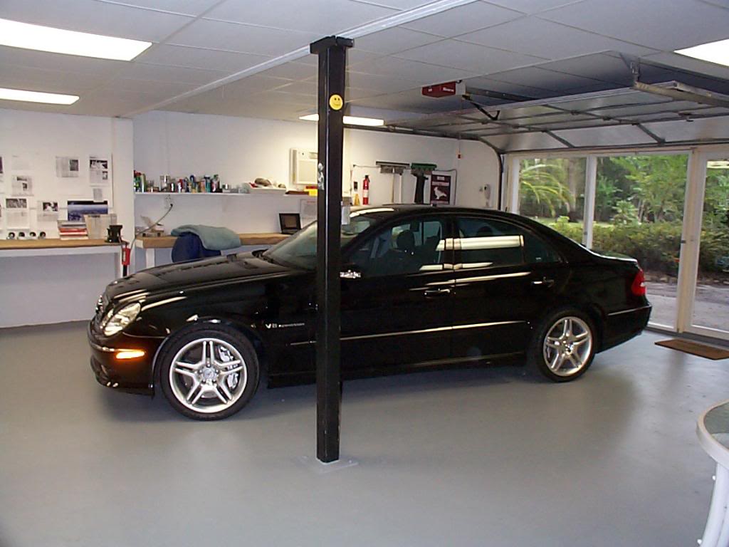
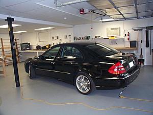
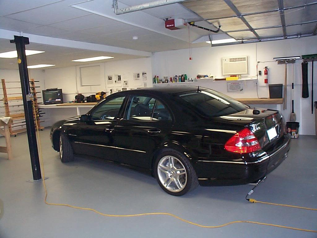
The victim, a 2004 E55 with Command, the SDS is programed to phone present (bluetooth puck with tail) this setting will allow the I-Pod integration to operate as plug and play.
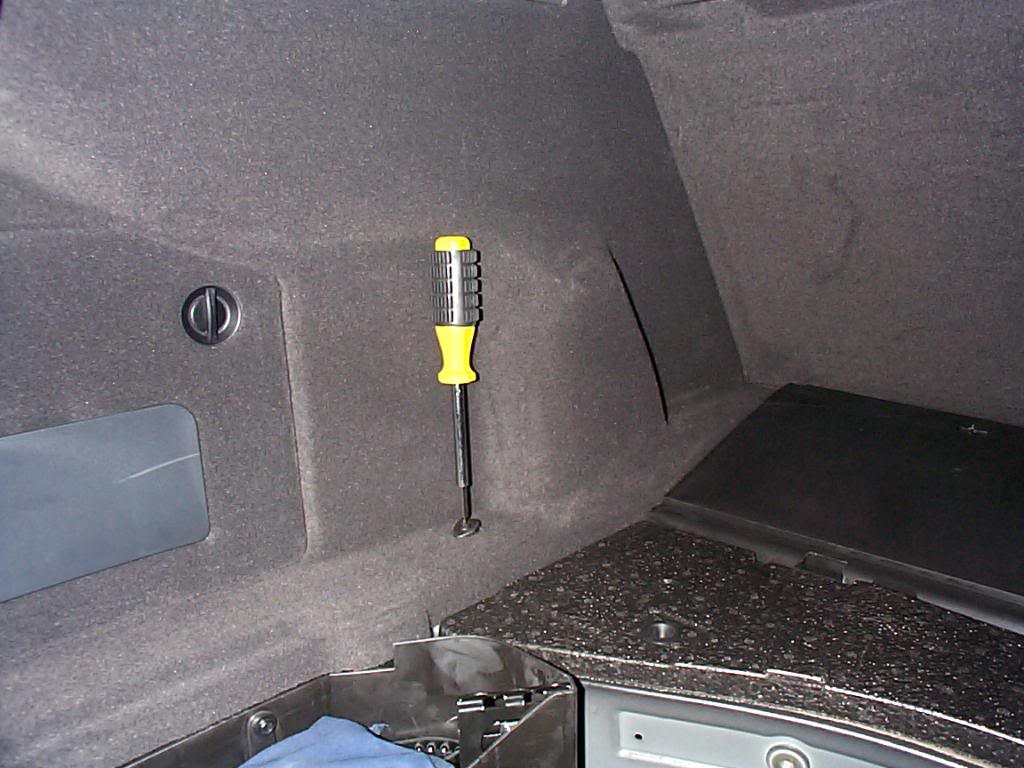
Step one remove all panels in the trunk. Remove expanding rivets (2 each side) at the top by the trunk lid hinges.
Remove the cargo net anchors (2 each side)
Pry out the frames that surround the trunk lid hinges, I just taped them out of the way. At this point you can remove all the panels, on the right and left side panels you must bend them and disengage them from the forward panel, this process requires some man handling of the panels. Try to use a gradual bend them rather than a sharp fold.

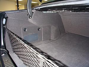
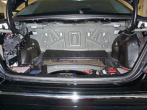
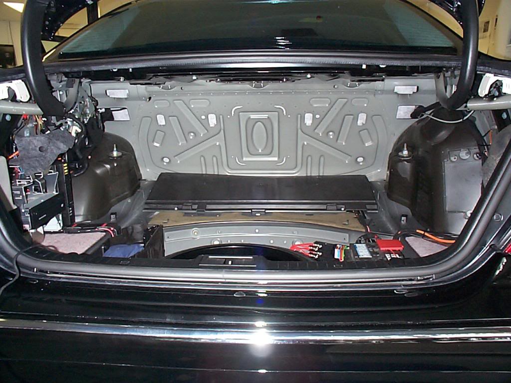
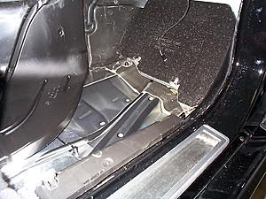
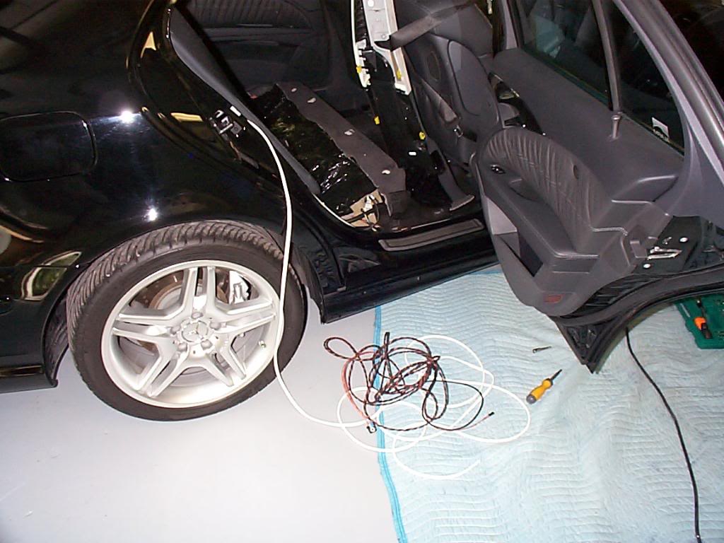
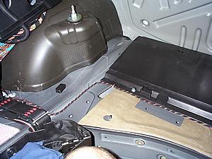
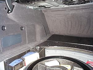
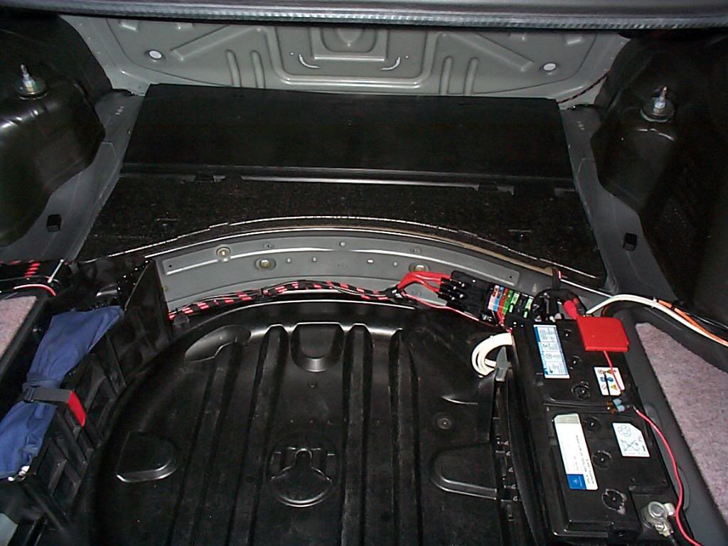
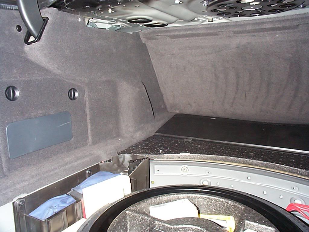
This is what it looks like with the panels removed. note I have the spare tire and I removed it at this time.
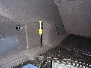
Forward right side of trunk this is the route the wires will take.
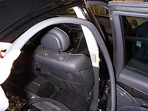
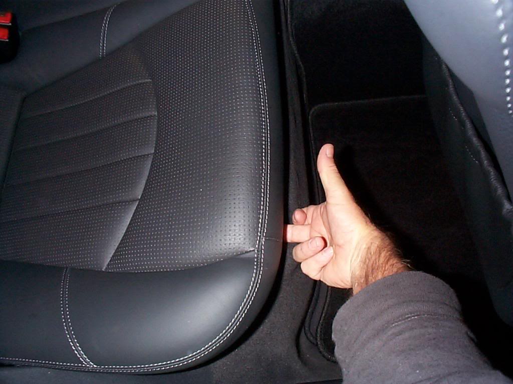
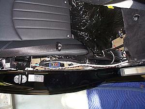
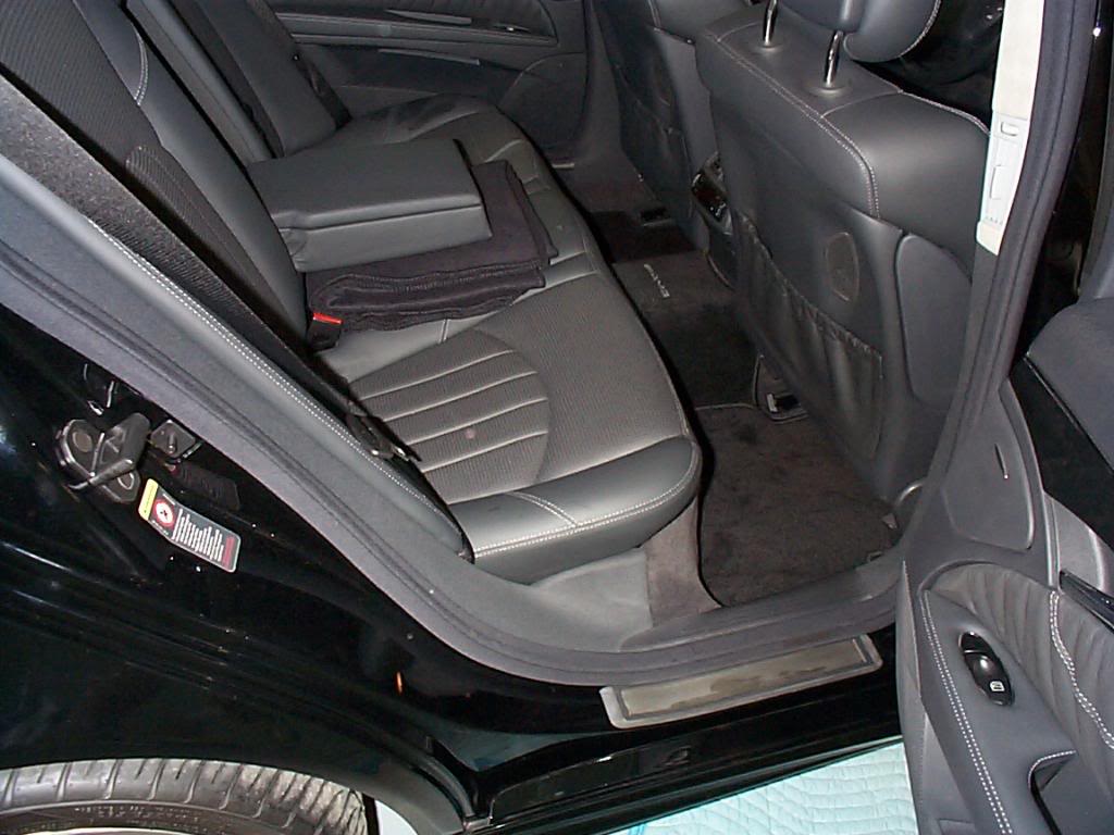
Time to start on interior, this pic is the rear seat and the release buttons under seat.

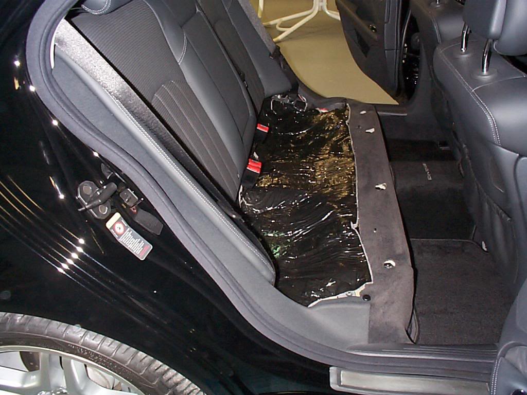
Here we have the seat removed.

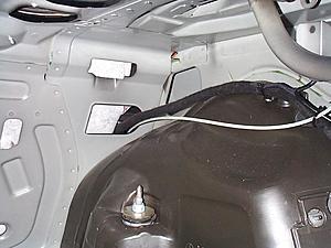
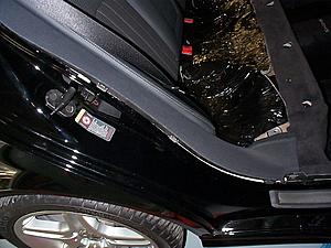
If after you remove the rear seat you smell gasoline you need to see your dealer, this cover is on the drivers side and covers the fuel pump and it has an update/recall.
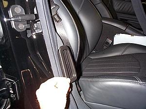
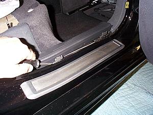
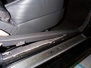
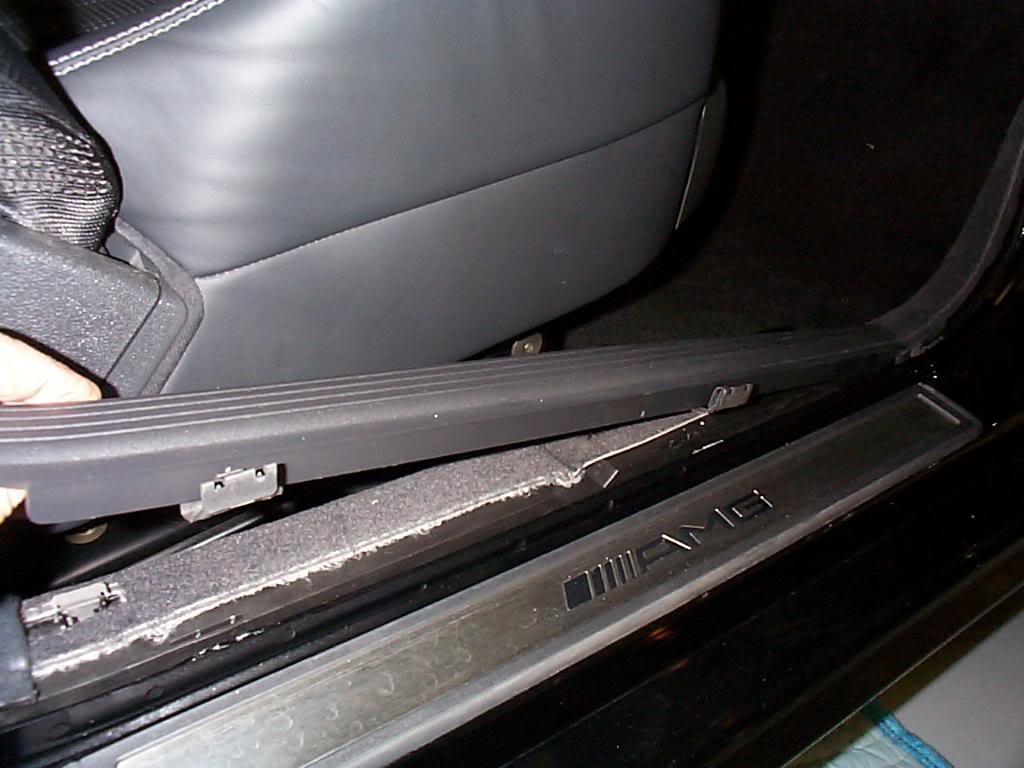
On passenger side, remove the threshold seal, this can be removed by hand.
Step one remove all panels in the trunk. Remove expanding rivets (2 each side) at the top by the trunk lid hinges.

Remove the cargo net anchors (2 each side)
Pry out the frames that surround the trunk lid hinges, I just taped them out of the way. At this point you can remove all the panels, on the right and left side panels you must bend them and disengage them from the forward panel, this process requires some man handling of the panels. Try to use a gradual bend them rather than a sharp fold.
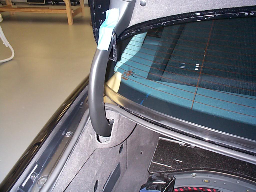
This is what it looks like with the panels removed. note I have the spare tire and I removed it at this time.
Forward right side of trunk this is the route the wires will take.

Time to start on interior, this pic is the rear seat and the release buttons under seat.
Here we have the seat removed.
If after you remove the rear seat you smell gasoline you need to see your dealer, this cover is on the drivers side and covers the fuel pump and it has an update/recall.

On passenger side, remove the threshold seal, this can be removed by hand.

Last edited by Yacht Master; 10-19-2008 at 11:12 AM.
10-18-2008 | 11:14 PM
#3
Thread Starter
MBWorld Fanatic!
Joined: Oct 2006
Posts: 3,642
Likes: 11
From: Caribbean/Florida/Colorado
E-ZGO 53hp., 1999 E 430 sport, 2004 E 55, 2008 Tahoe LTZ on 24"s
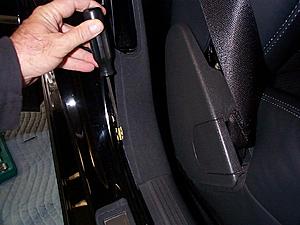
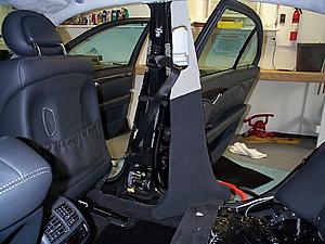
Same for front passenger side, remove air conditioning grill and threshold seal both by hand.
Rear door gently pry kick plate clips up, and remove plastic plate.
Remove 10mm plastic nut and expanding rivet from side finish panel.
Pry the clips up as you lift on the finish panel.
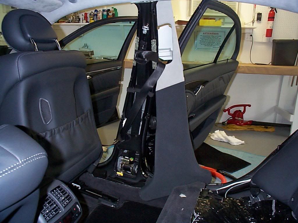
Rear door pry loose only clips for "B" pillar.****This step may not be necessary, I took the time to remove the "B" pillar cover so that I could see the wire run, and make sure it would not foul the seat belt mechanism. The wires pass in a boxed tube, and would have no problem to be fished through this conduit to the forward foot well.****
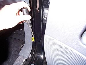
Front door pry loose only clips for "B" pillar.****This step may not be necessary, I took the time to remove the "B" pillar cover so that I could see the wire run, and make sure it would not foul the seat belt mechanism. The wires pass in a boxed tube, and would have no problem to be fished through this conduit to the forward foot well.****
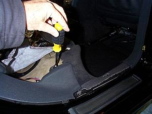
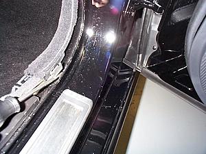
Pry the front door kick plate up at the clips, and remove.
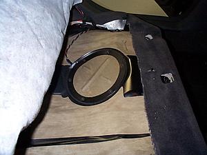
Here we pry the forward kick panel in the foot well loose, If you have factory phone there will be a speaker in this panel.
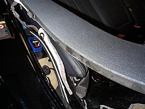
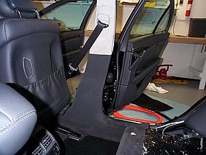
Adjust the passenger seat to the forward most position. Now the "B" pillar cover can be removed, pull extra slack out of the seat belt and return the seat to the rearward most position, holding the "B" pillar cover out of the way.
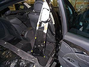
OK here we are at the foot well.

Rear door gently pry kick plate clips up, and remove plastic plate.

Remove 10mm plastic nut and expanding rivet from side finish panel.

Pry the clips up as you lift on the finish panel.

Rear door pry loose only clips for "B" pillar.****This step may not be necessary, I took the time to remove the "B" pillar cover so that I could see the wire run, and make sure it would not foul the seat belt mechanism. The wires pass in a boxed tube, and would have no problem to be fished through this conduit to the forward foot well.****

Front door pry loose only clips for "B" pillar.****This step may not be necessary, I took the time to remove the "B" pillar cover so that I could see the wire run, and make sure it would not foul the seat belt mechanism. The wires pass in a boxed tube, and would have no problem to be fished through this conduit to the forward foot well.****

Pry the front door kick plate up at the clips, and remove.
Here we pry the forward kick panel in the foot well loose, If you have factory phone there will be a speaker in this panel.

Adjust the passenger seat to the forward most position. Now the "B" pillar cover can be removed, pull extra slack out of the seat belt and return the seat to the rearward most position, holding the "B" pillar cover out of the way.

OK here we are at the foot well.
Last edited by Yacht Master; 10-19-2008 at 11:55 AM.
10-18-2008 | 11:20 PM
#4
Thread Starter
MBWorld Fanatic!
Joined: Oct 2006
Posts: 3,642
Likes: 11
From: Caribbean/Florida/Colorado
E-ZGO 53hp., 1999 E 430 sport, 2004 E 55, 2008 Tahoe LTZ on 24"s
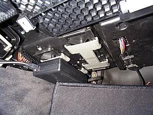
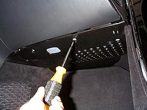
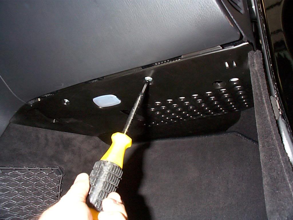
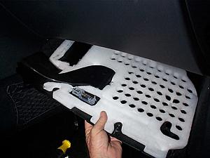
In the foot well under the glove box is this panel it is held in place by 2 screws.
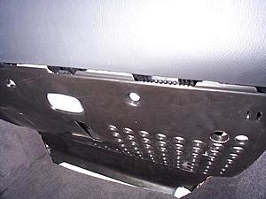
As you remove the panel, disconnect the wire to the lamp.
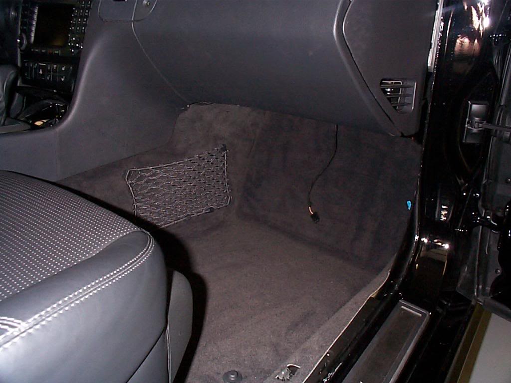
On the right side of the foot well remove the kick panel by sliding it to the rear. This panel has a phone speaker that needs to be disconnected and will require a small tool that can depress the lock in the connector. I use a brass O ring tool.
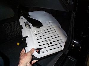
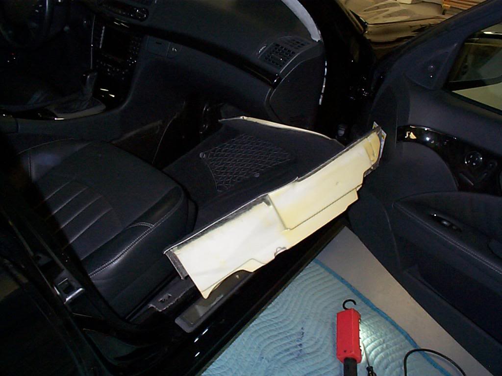
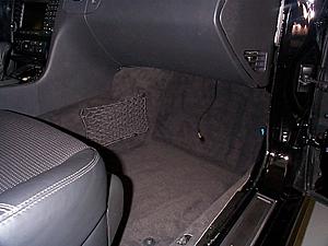
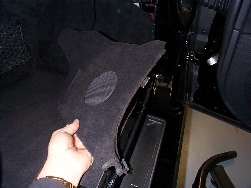
Make sure the seat is back as far as it will go, and as high as it will go. Fold the forward part of the carpet down and lift the rear part out of the foot well this is a big piece to deal with but but it will come out. You will be shocked at how much it weighs.

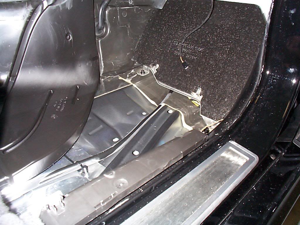
Carpet and foam backing removed.
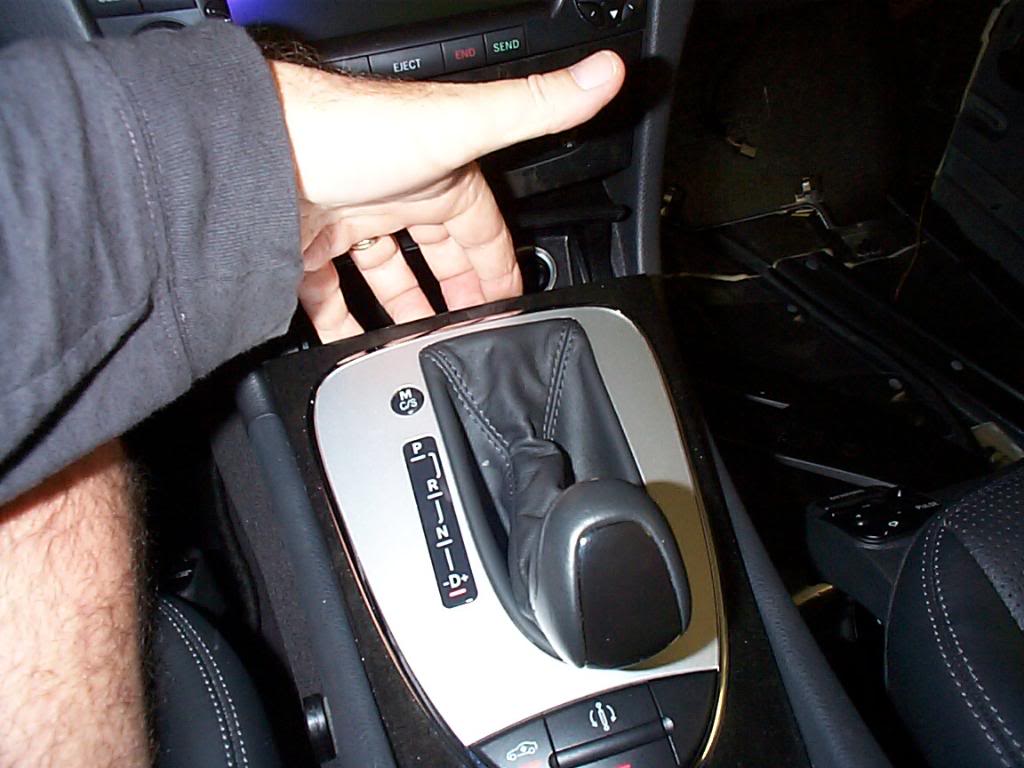
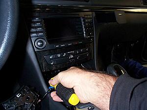
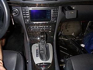
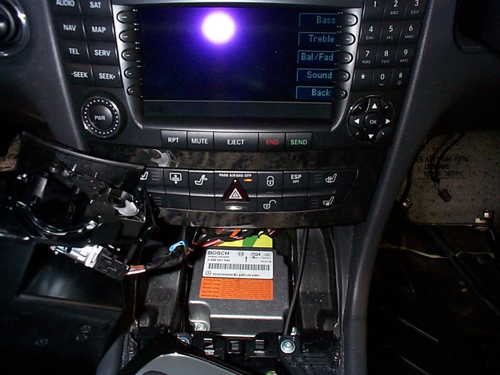
Turn on the ignition and set park brake then move gear selector to Drive position, then remove the ashtray, just the tray part.
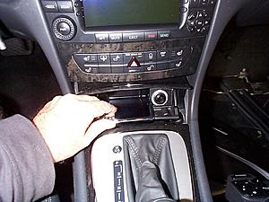
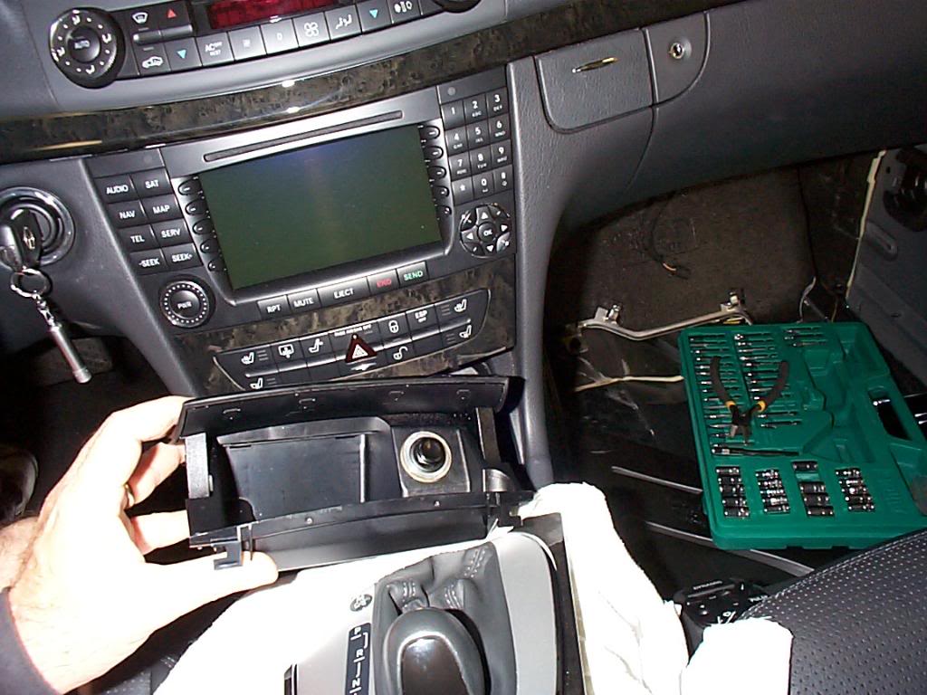
Now you can move the gear selector surround. Gently lift on the forward edge and it will pop loose, lift ti and move it to the rear. I used rags to prevent any damage to the console or the surround.
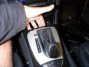
Remove ash tray housing and unplug electrical connection.
A good pic of the rags, notice still in gear.
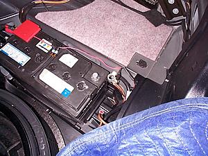
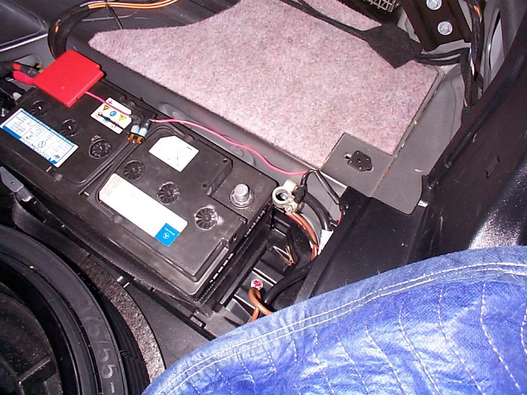
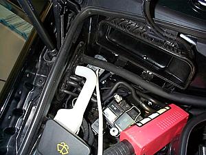
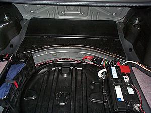
At this point it is a good idea to disconnect the battery, just the negative post is all that is necessary. The fuse and wire you see on top of my battery is connected to a 1.5 amp on-board automatic charger.

As you remove the panel, disconnect the wire to the lamp.

On the right side of the foot well remove the kick panel by sliding it to the rear. This panel has a phone speaker that needs to be disconnected and will require a small tool that can depress the lock in the connector. I use a brass O ring tool.
Make sure the seat is back as far as it will go, and as high as it will go. Fold the forward part of the carpet down and lift the rear part out of the foot well this is a big piece to deal with but but it will come out. You will be shocked at how much it weighs.
Carpet and foam backing removed.
Turn on the ignition and set park brake then move gear selector to Drive position, then remove the ashtray, just the tray part.
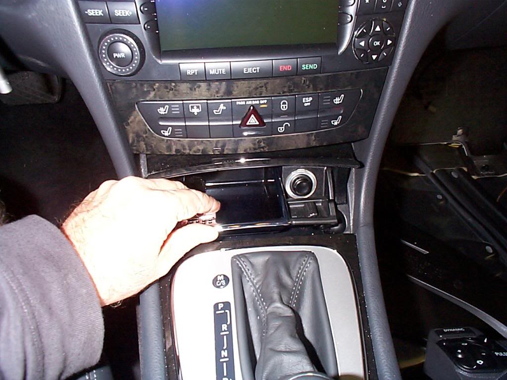
Now you can move the gear selector surround. Gently lift on the forward edge and it will pop loose, lift ti and move it to the rear. I used rags to prevent any damage to the console or the surround.
Remove ash tray housing and unplug electrical connection.
A good pic of the rags, notice still in gear.

At this point it is a good idea to disconnect the battery, just the negative post is all that is necessary. The fuse and wire you see on top of my battery is connected to a 1.5 amp on-board automatic charger.
Last edited by Yacht Master; 10-19-2008 at 12:53 PM.
10-18-2008 | 11:25 PM
#5
Thread Starter
MBWorld Fanatic!
Joined: Oct 2006
Posts: 3,642
Likes: 11
From: Caribbean/Florida/Colorado
E-ZGO 53hp., 1999 E 430 sport, 2004 E 55, 2008 Tahoe LTZ on 24"s
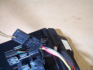
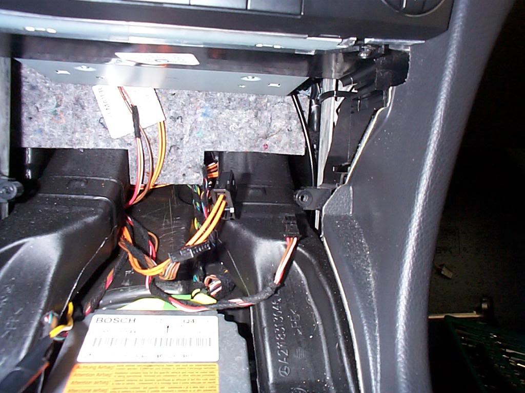
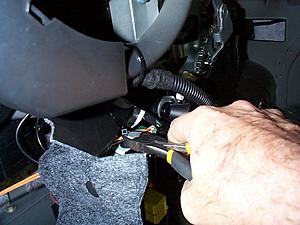
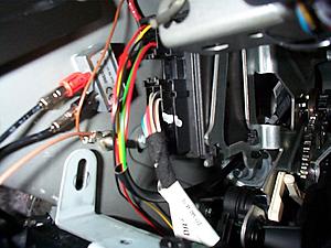
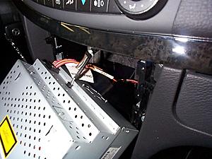
Back inside the car, this is the connectors to the CD magazine, two electrical connectors and one fiber optic. The electrical connectors are difficult to disconnect, you will need a tool to release the locks in the connectors and there is not much space or slack in the wire to work with. This requires some patience. The fiber optic is easy.
Here is the location of the lock on the 6 wire plug.

Here is the location of the lock on the 3 wire plug.
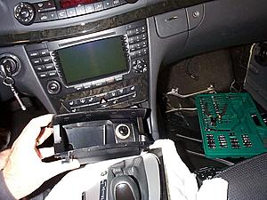
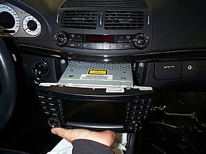
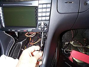
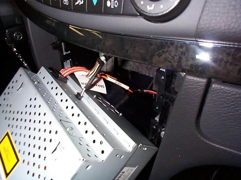
Once the wires and fiber optic are disconnected remove 2 screws under the CD magazine and remove the unit.

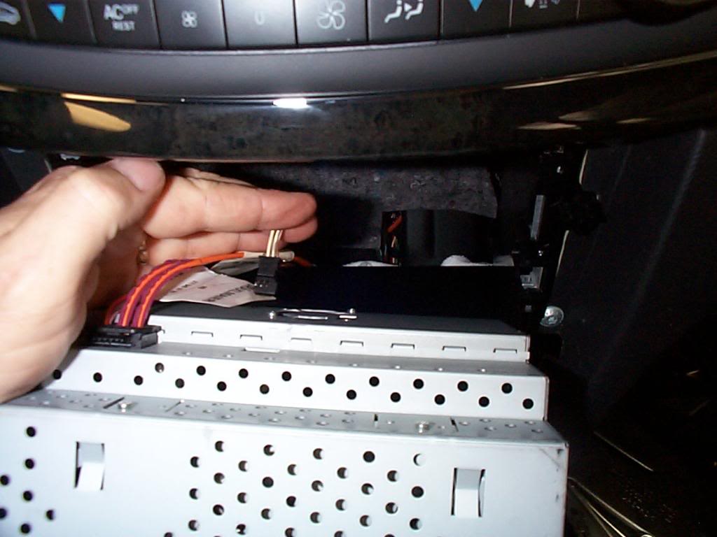
Under the command head unit are 2 screws that clamp the head unit in place you must unscrew them till they stop (they don't come out) in order to slide the head unit out.
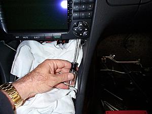
Gently slide the head unit out.
Only disconnect the 3 wire plug, (this goes to the jack in glove box) and slide head unit back in.

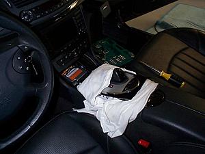
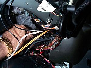
The time has come to install the wire loom, I pass the loom (end with small connectors first) through the rear bulkhead and pull enough extra wire to reach the left rear of the car. The white wire is 2-14 boat cable for future 12V mods under the hood, this is a good time to run the wire, it is not a part of the I-Pod install.

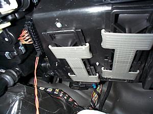
Next the SAM (signal acquisition module) needs to have its mounting nuts (3) removed, first one at top.
Second on right side of SAM.

Here is the location of the lock on the 6 wire plug.
Here is the location of the lock on the 3 wire plug.

Once the wires and fiber optic are disconnected remove 2 screws under the CD magazine and remove the unit.
Under the command head unit are 2 screws that clamp the head unit in place you must unscrew them till they stop (they don't come out) in order to slide the head unit out.
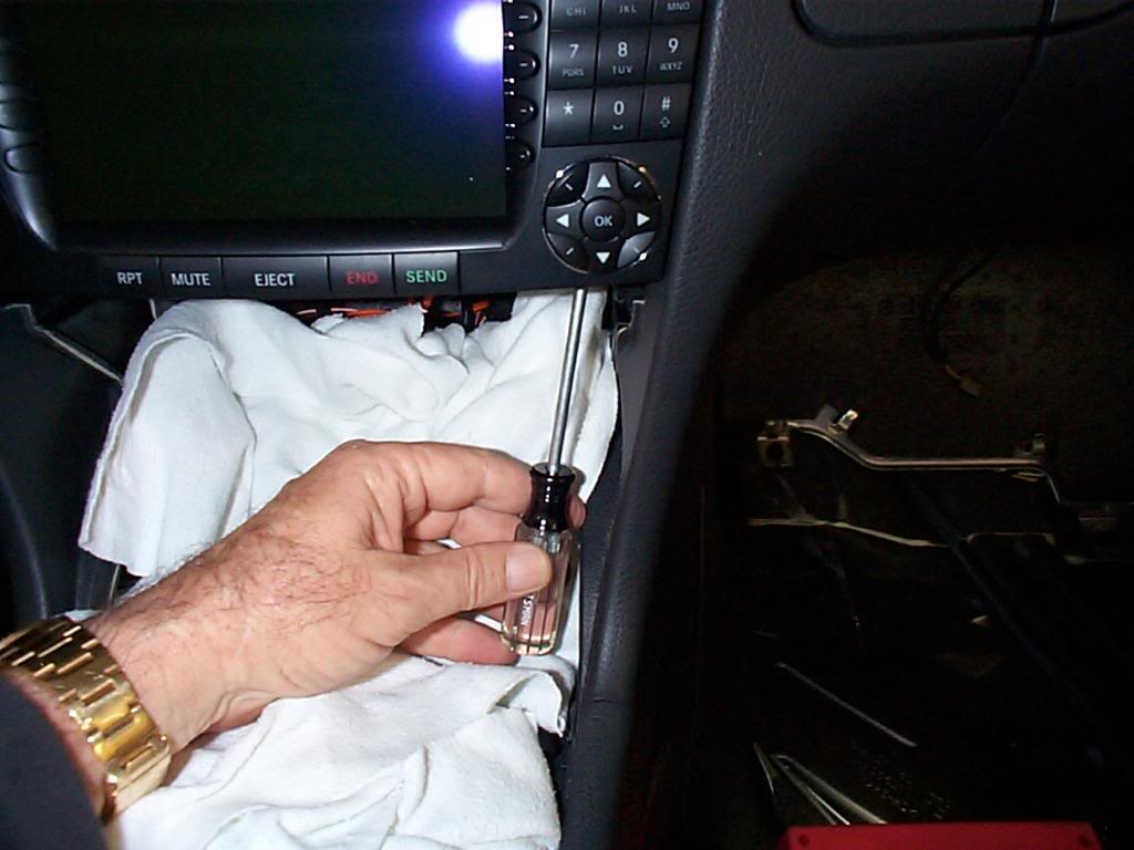
Gently slide the head unit out.

Only disconnect the 3 wire plug, (this goes to the jack in glove box) and slide head unit back in.
The time has come to install the wire loom, I pass the loom (end with small connectors first) through the rear bulkhead and pull enough extra wire to reach the left rear of the car. The white wire is 2-14 boat cable for future 12V mods under the hood, this is a good time to run the wire, it is not a part of the I-Pod install.
Next the SAM (signal acquisition module) needs to have its mounting nuts (3) removed, first one at top.
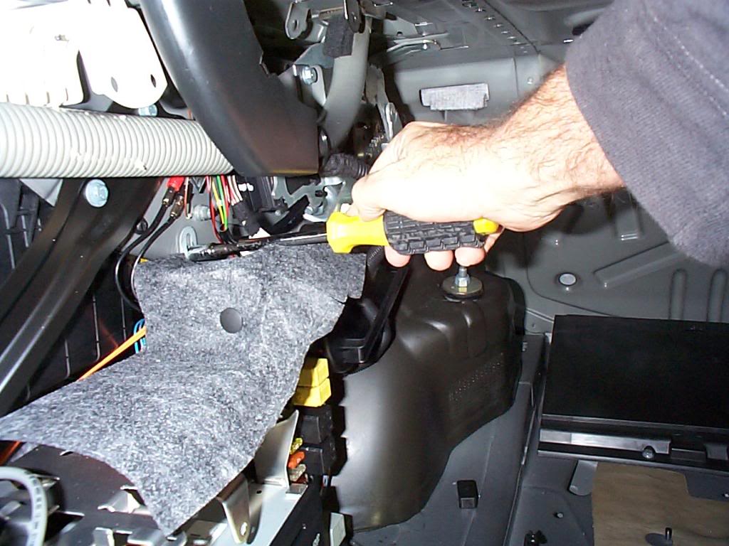
Second on right side of SAM.
Last edited by Yacht Master; 10-19-2008 at 04:03 PM.
10-18-2008 | 11:29 PM
#6
Thread Starter
MBWorld Fanatic!
Joined: Oct 2006
Posts: 3,642
Likes: 11
From: Caribbean/Florida/Colorado
E-ZGO 53hp., 1999 E 430 sport, 2004 E 55, 2008 Tahoe LTZ on 24"s
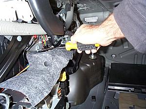
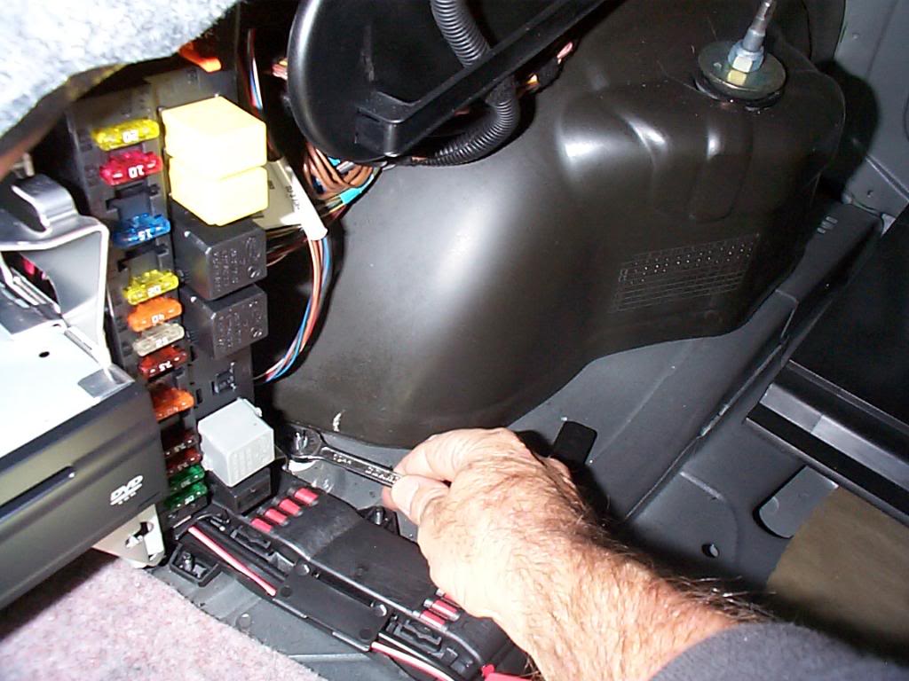
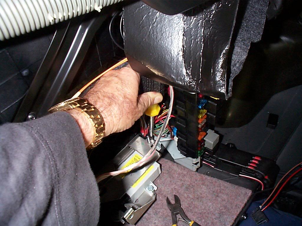
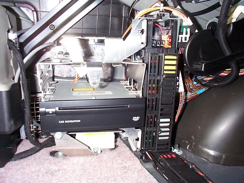
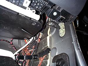
To get to the third nut holding the SAM, the DVD nav drive needs to be removed, a single screw holds it and its bracket in place, remove screw and swing the DVD out, disconnect electrical and fiber optic cable and remove from car. Then you can remove the final nut.

Cut the tie wrap on top of the SAM.
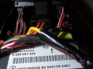
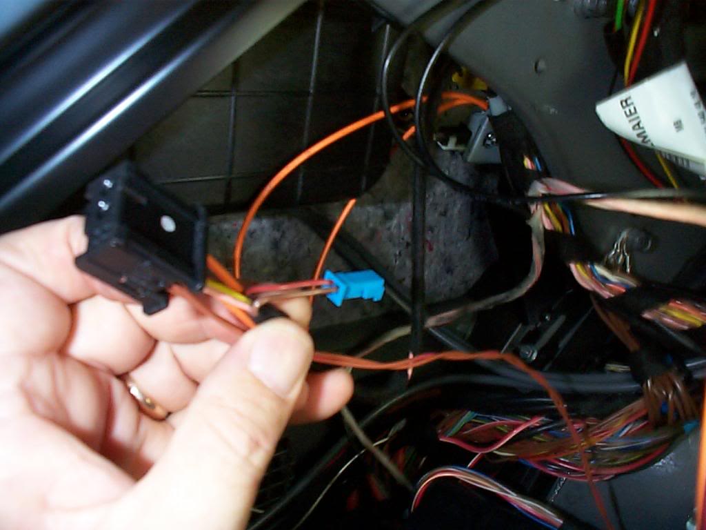
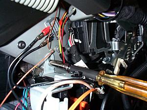
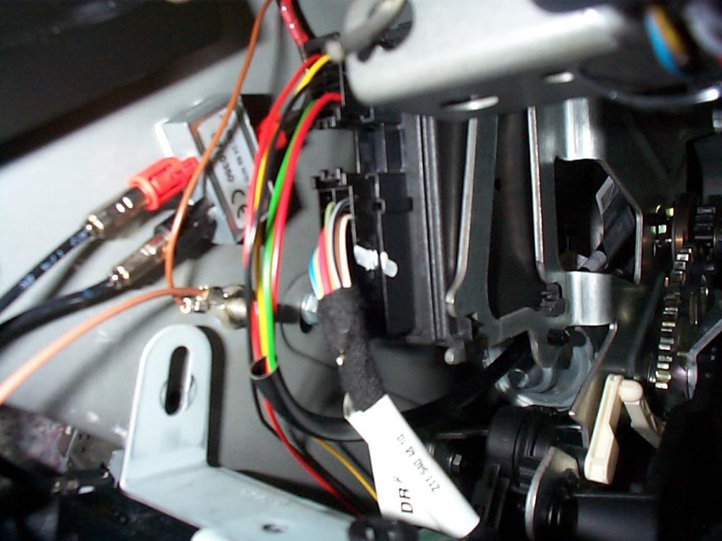
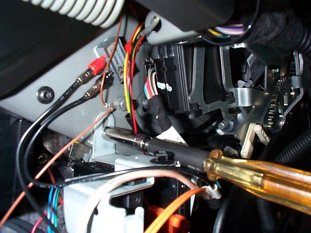
Above and outboard from the SAM is the audio gateway it is very difficult to get to, this pic is my failed attempt to remove it, that did not work. what needs to be done is remove the plug on the top of the audio gateway (even-though you cant see it) after many attempts I finally got the wire unplugged this was the most difficult task of the project.
This is all you can see of the audio gateway
Yea unplugged
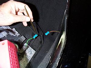
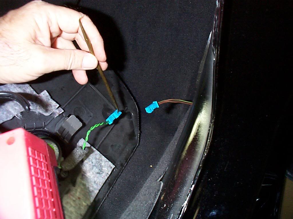
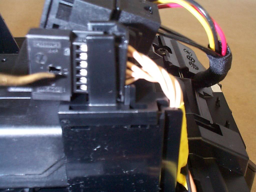
Now it gets interesting, you must split the plug out, the electrical splits from the fiber optic. Then you need to pin out the brown wire and replace it with the brown wire from the I-Pod loom, make sure it clicks in place securely.

Next pin out the brown & red wire from the blue plug on the I-Pod loom. Then pin out the brown & red from the plug and put the brown & red from the I-Pod in the plug.

You will have a brown and brown & red wires left over put both in the blue connector that is left over and tie wrap it back to the loom. All we have done here is swap the wires so that the I-Pod loom is on line and the original wires are terminated. You can now put the plugs together and plug it in to the audio gateway.
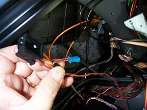
On the back side of the SAM is the power plug #27 plug the red wire plug in here. (won't go anywhere else).
You can now start to re fasten the SAM
Cut the tie wrap on top of the SAM.

Above and outboard from the SAM is the audio gateway it is very difficult to get to, this pic is my failed attempt to remove it, that did not work. what needs to be done is remove the plug on the top of the audio gateway (even-though you cant see it) after many attempts I finally got the wire unplugged this was the most difficult task of the project.
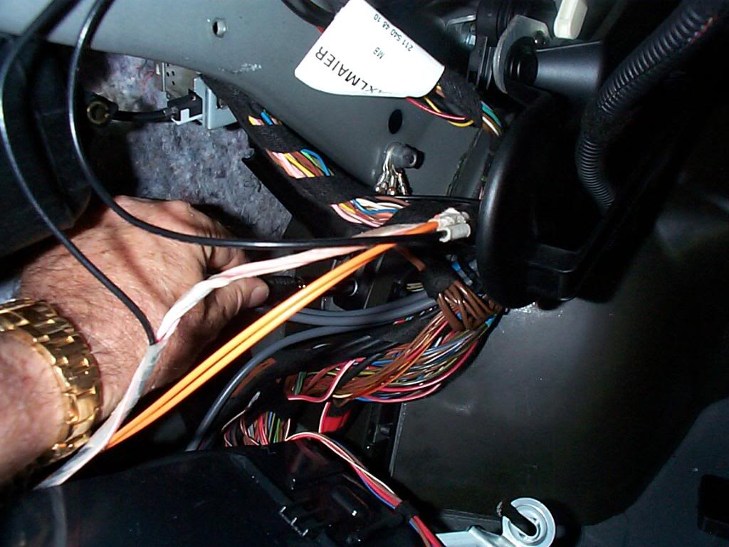
This is all you can see of the audio gateway

Yea unplugged
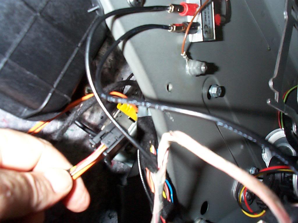
Now it gets interesting, you must split the plug out, the electrical splits from the fiber optic. Then you need to pin out the brown wire and replace it with the brown wire from the I-Pod loom, make sure it clicks in place securely.
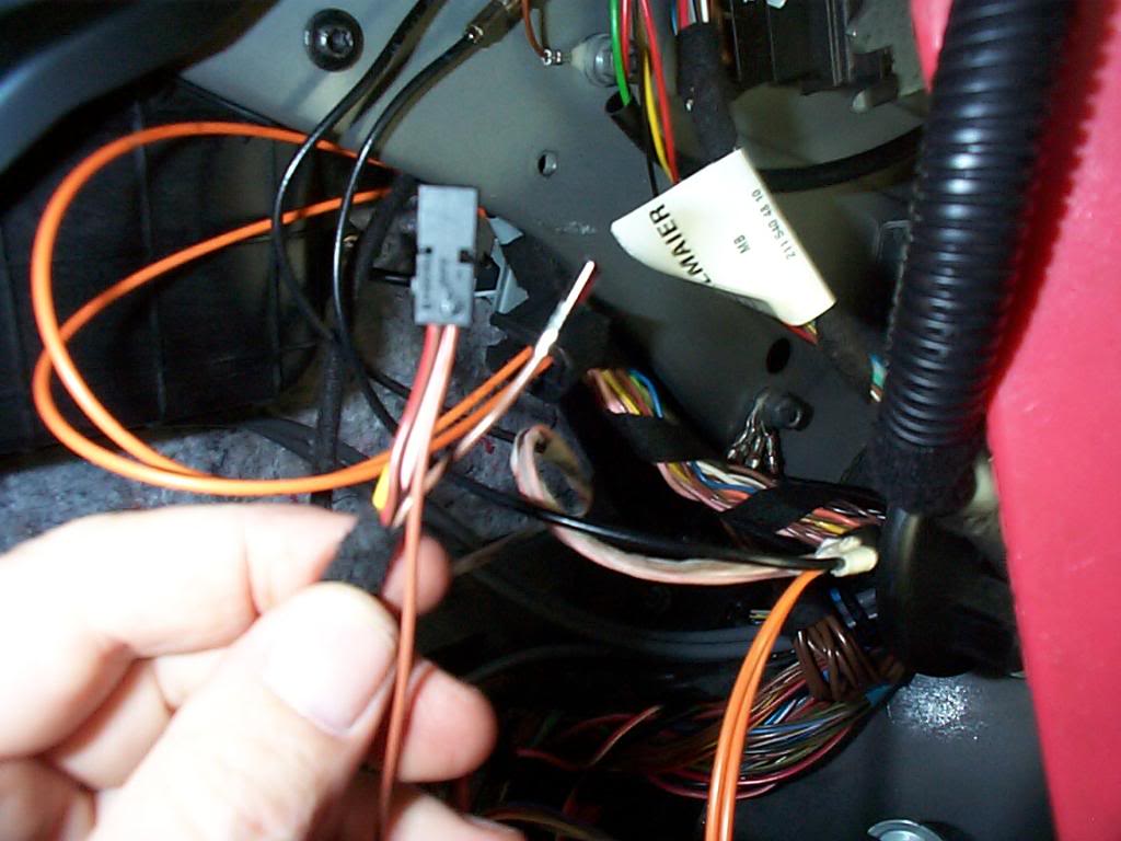
Next pin out the brown & red wire from the blue plug on the I-Pod loom. Then pin out the brown & red from the plug and put the brown & red from the I-Pod in the plug.
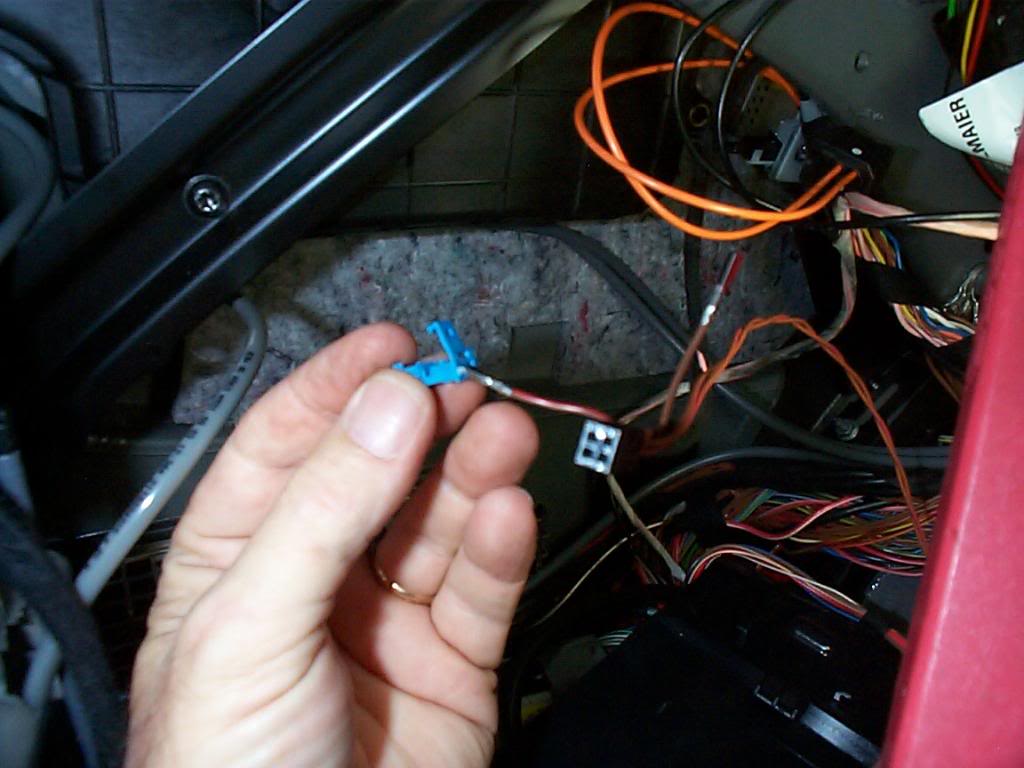
You will have a brown and brown & red wires left over put both in the blue connector that is left over and tie wrap it back to the loom. All we have done here is swap the wires so that the I-Pod loom is on line and the original wires are terminated. You can now put the plugs together and plug it in to the audio gateway.
On the back side of the SAM is the power plug #27 plug the red wire plug in here. (won't go anywhere else).
You can now start to re fasten the SAM
Last edited by Yacht Master; 10-19-2008 at 05:01 PM.
10-18-2008 | 11:36 PM
#7
Thread Starter
MBWorld Fanatic!
Joined: Oct 2006
Posts: 3,642
Likes: 11
From: Caribbean/Florida/Colorado
E-ZGO 53hp., 1999 E 430 sport, 2004 E 55, 2008 Tahoe LTZ on 24"s
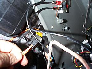
The connection for the ground is right by the SAM's upper mount.
All 3 SAM mount nuts can be tightened down now.
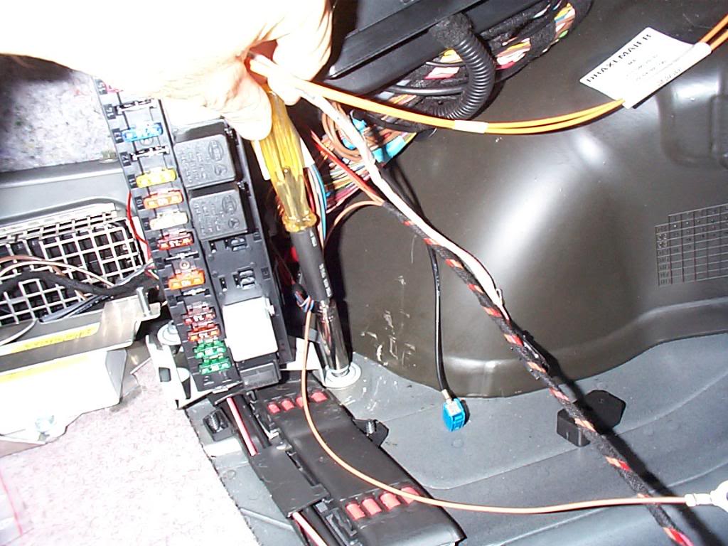
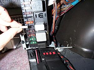
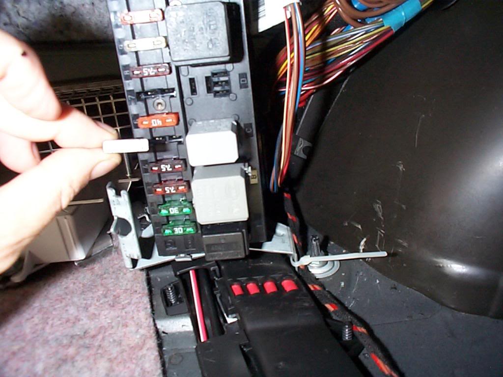
The relay goes in the SAM's relay slot "C" third from the bottom.
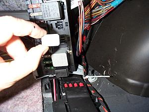
The fuse goes in "#5" fifth from the bottom.
Reinstall the NAV DVD and the fuse/relay cover, replace tie wrap on the top of the SAM that holds wires and fiber optics.
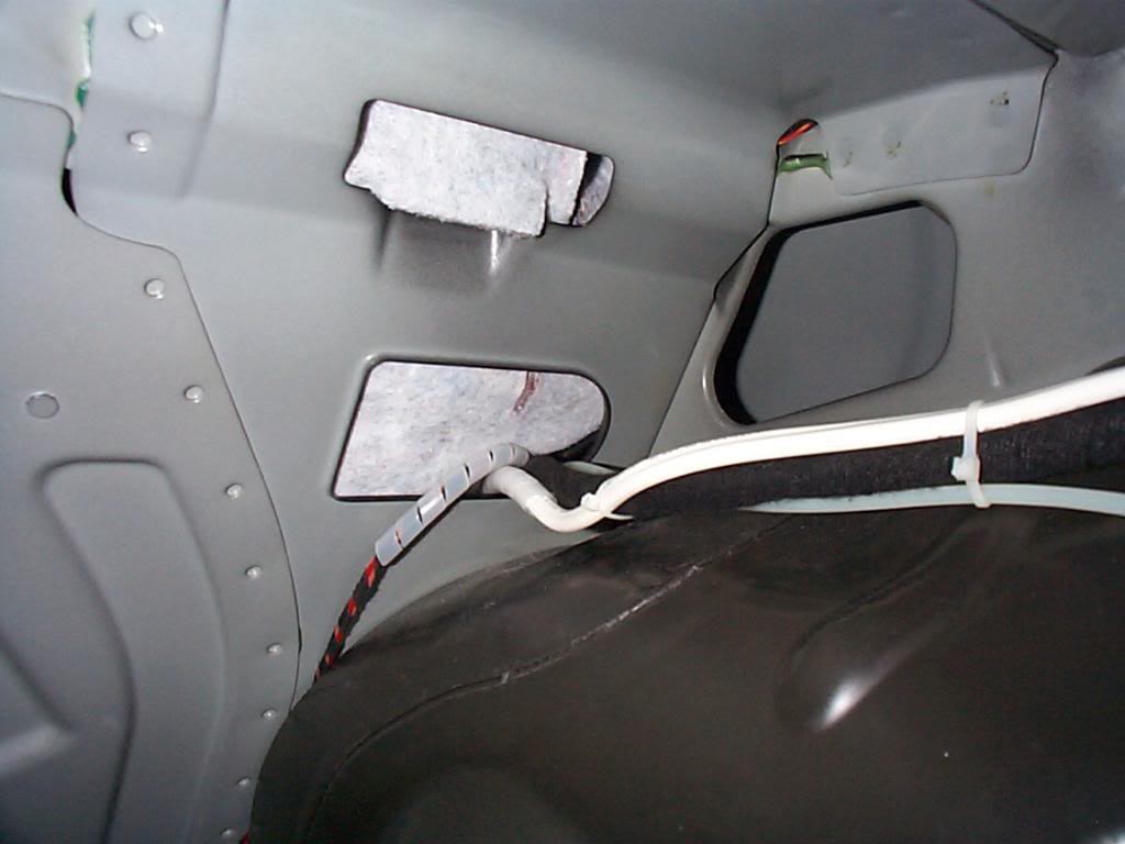
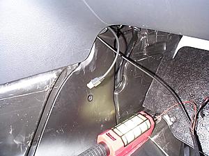
Route the wire so as to avoid damage from any cargo in the trunk, I did not use the supplied felt, cause I ran the wire where it could not get crushed.
I added some chaffing material at the bulkhead pass through, like all stampings it has a sharp edge.

Chaffing in position
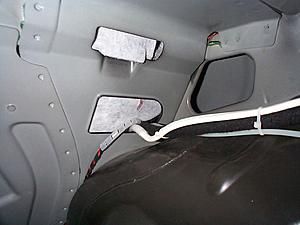
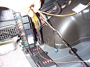
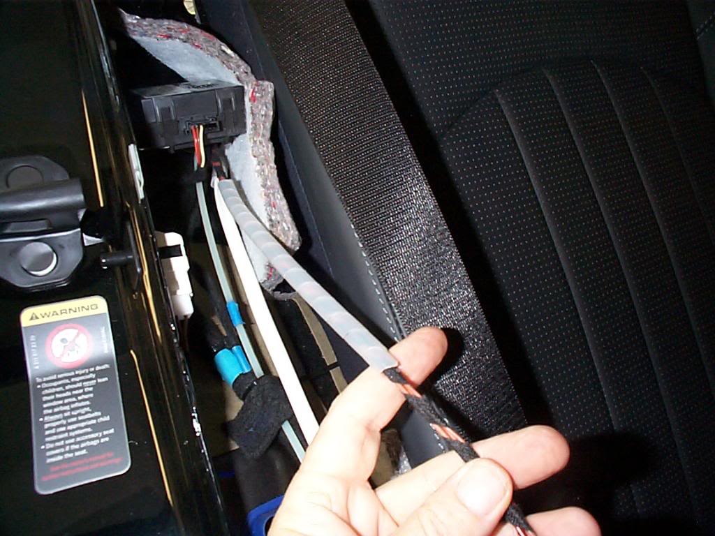
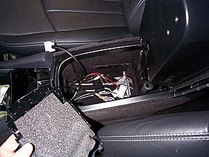
Routing wires along side rear seat, tie wrapped in position. The wire run that goes forward to the foot well simply opens at the top and you can drop the wires in.
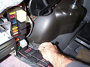
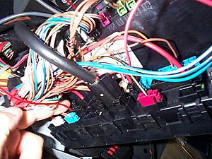
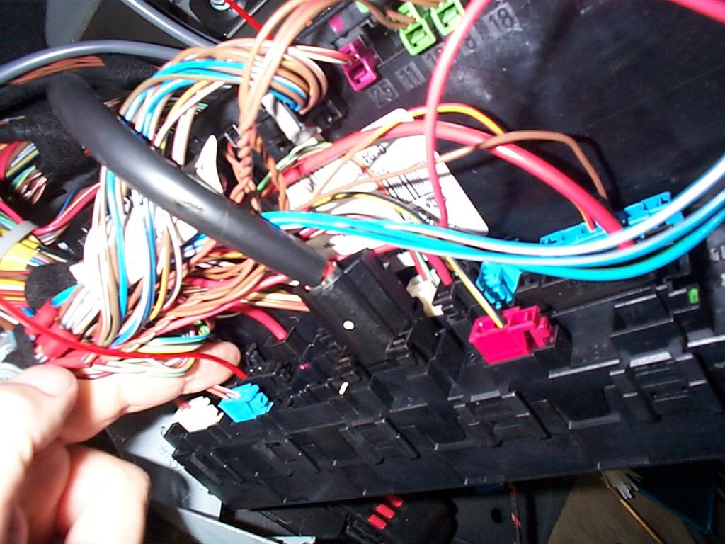
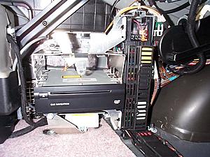
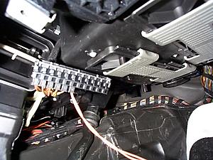
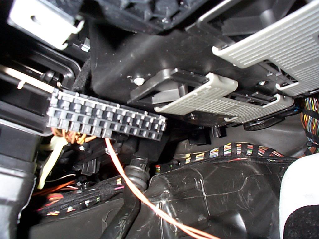
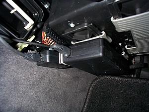
Here we are in the foot well and getting close to being all connected. our next connection is to the CAN buss, to connect remove the buss from its mount this will allow you to plug in to the can buss fully and when you replace the buss it locks all the plugs in. There is a better pic of this later in the DIY.
All 3 SAM mount nuts can be tightened down now.
The relay goes in the SAM's relay slot "C" third from the bottom.

The fuse goes in "#5" fifth from the bottom.
Reinstall the NAV DVD and the fuse/relay cover, replace tie wrap on the top of the SAM that holds wires and fiber optics.
Route the wire so as to avoid damage from any cargo in the trunk, I did not use the supplied felt, cause I ran the wire where it could not get crushed.

I added some chaffing material at the bulkhead pass through, like all stampings it has a sharp edge.
Chaffing in position
Routing wires along side rear seat, tie wrapped in position. The wire run that goes forward to the foot well simply opens at the top and you can drop the wires in.

Here we are in the foot well and getting close to being all connected. our next connection is to the CAN buss, to connect remove the buss from its mount this will allow you to plug in to the can buss fully and when you replace the buss it locks all the plugs in. There is a better pic of this later in the DIY.

Last edited by Yacht Master; 10-19-2008 at 05:48 PM.
Trending Topics
10-18-2008 | 11:40 PM
#8
Thread Starter
MBWorld Fanatic!
Joined: Oct 2006
Posts: 3,642
Likes: 11
From: Caribbean/Florida/Colorado
E-ZGO 53hp., 1999 E 430 sport, 2004 E 55, 2008 Tahoe LTZ on 24"s
From the foot well you can see a passage to the back of the head unit feed the 3 wire connector in to this passage. Withdraw the head unit from the dash and plug in the 3 wire plug from the I-Pod loom. You can then tie wrap the old 3 wire plug from glove box to the new wire so that it won't rattle around.
Slide the head unit back in and tighten down the clamp screws. Then slide the CD magazine back in and connect the electrical and fiber optic connections.
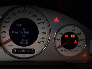
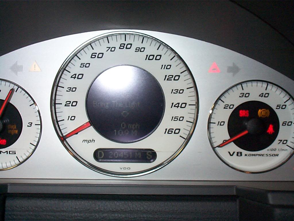
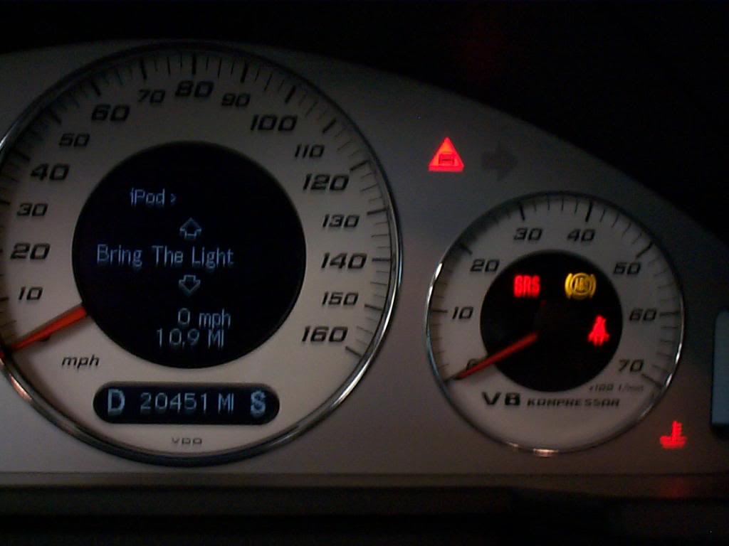
This is a good time to make a test, connect the I-Pod loom to the I-Pod interface and the I-Pod cable to the interface and your I-Pod re connect the main battery.

Bad Pic sorry.....
Turn on radio and hit AUX and Success it works! (Bring The Light Smashing Pumpkins Zeitgeist) sounds good to me.
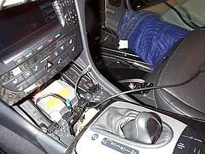
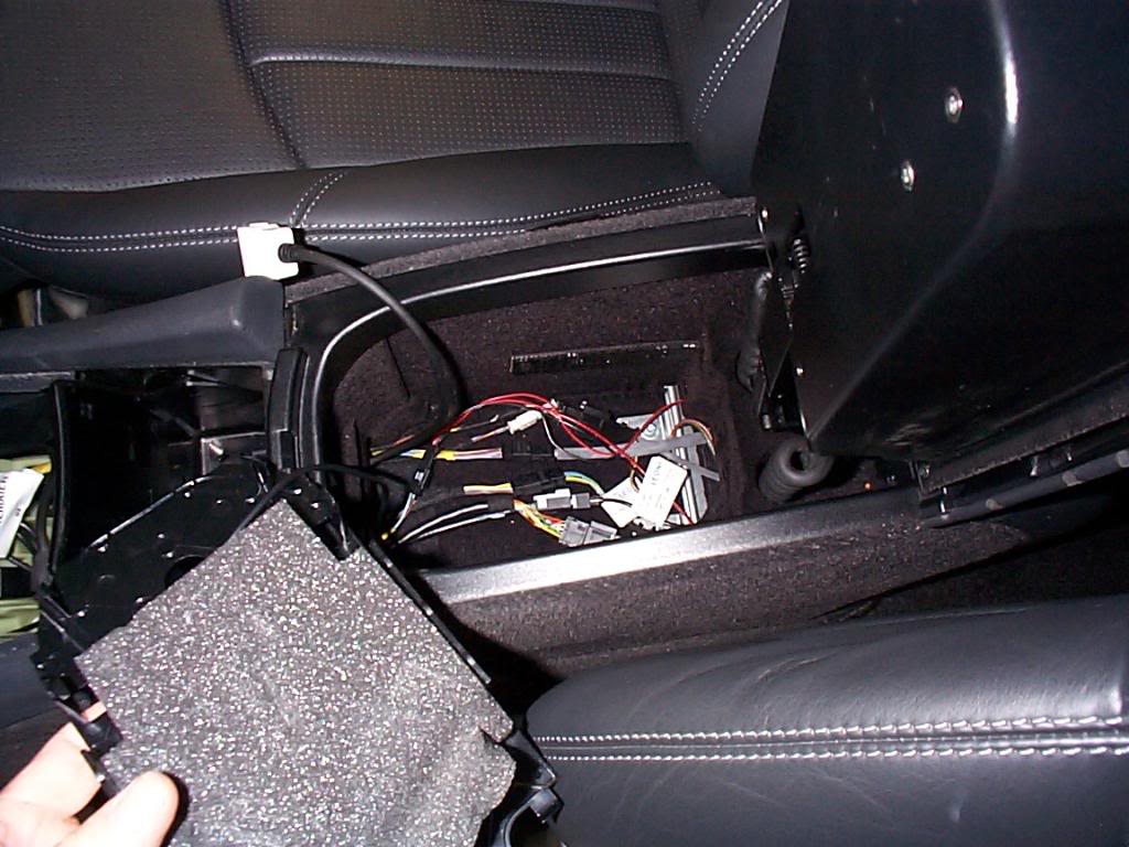
At this point I decided to deviate from the install instructions from MB. I chose to locate the I-Pod in the lower compartment of the center console over the normal in the glove box. In this pic I am sorting out the wire routing for the relocation.
Floor board removed from console, and I-Pod harness routed through console. note it is just long enough.
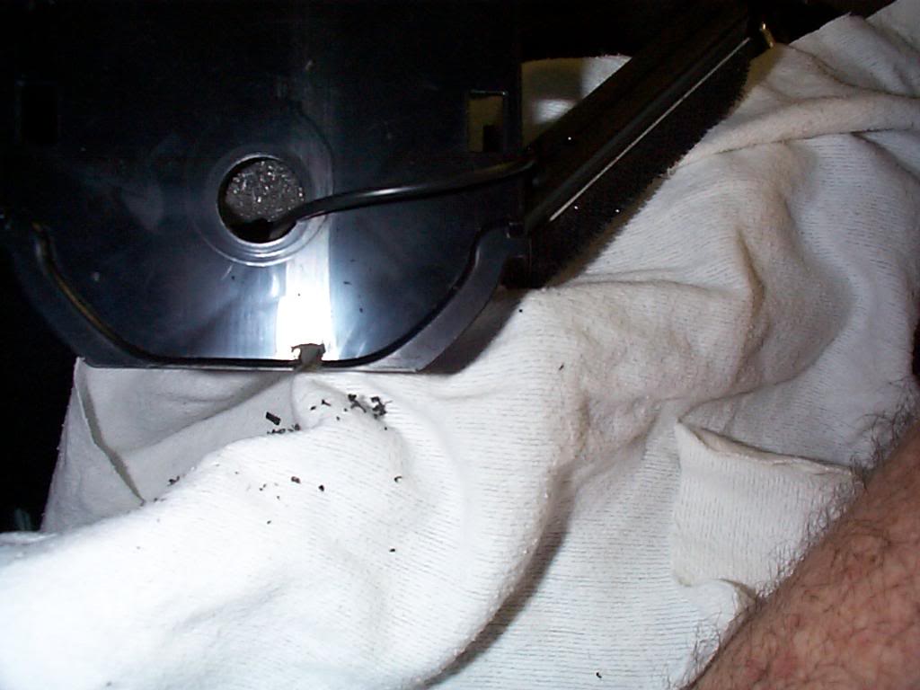
I had to cut down the grommet to make it fit, this is what was left after I removed the rubber.

See just long enough.
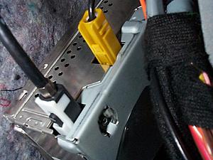
Here is the pic of the CAN buss "open" and plug fully inserted, once it is snapped back in to the mount all connections will be locked in.
Slide the head unit back in and tighten down the clamp screws. Then slide the CD magazine back in and connect the electrical and fiber optic connections.

This is a good time to make a test, connect the I-Pod loom to the I-Pod interface and the I-Pod cable to the interface and your I-Pod re connect the main battery.
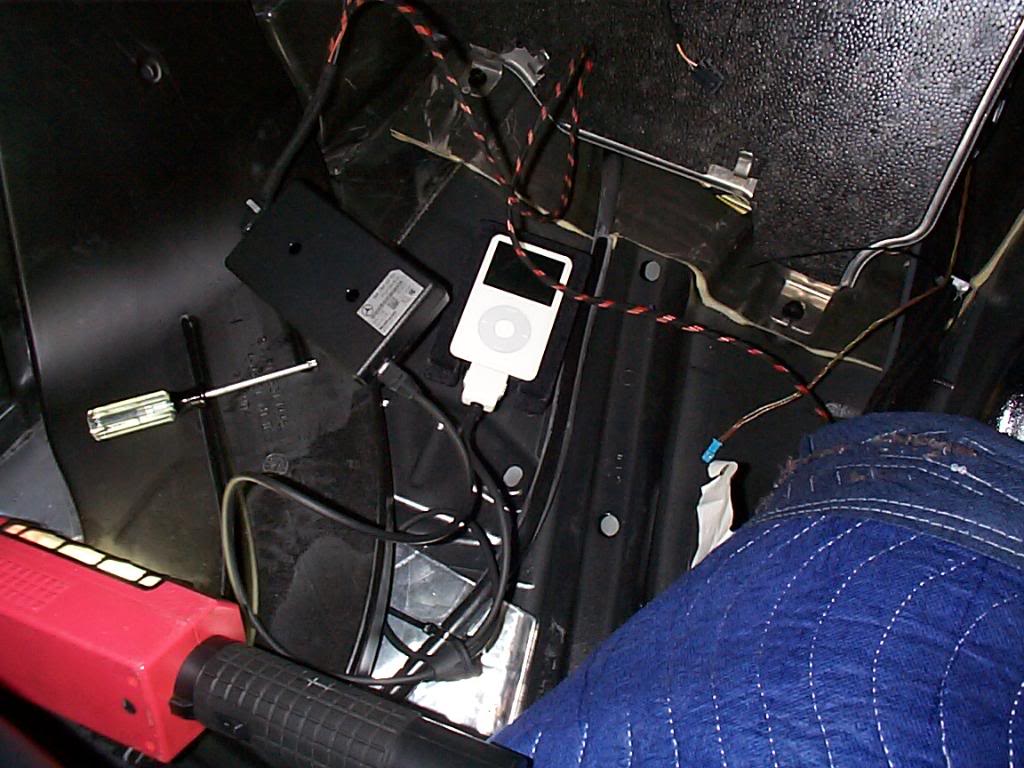
Bad Pic sorry.....
Turn on radio and hit AUX and Success it works! (Bring The Light Smashing Pumpkins Zeitgeist) sounds good to me.
At this point I decided to deviate from the install instructions from MB. I chose to locate the I-Pod in the lower compartment of the center console over the normal in the glove box. In this pic I am sorting out the wire routing for the relocation.

Floor board removed from console, and I-Pod harness routed through console. note it is just long enough.
I had to cut down the grommet to make it fit, this is what was left after I removed the rubber.
See just long enough.

Here is the pic of the CAN buss "open" and plug fully inserted, once it is snapped back in to the mount all connections will be locked in.
Last edited by Yacht Master; 10-19-2008 at 06:30 PM.
10-18-2008 | 11:46 PM
#9
Thread Starter
MBWorld Fanatic!
Joined: Oct 2006
Posts: 3,642
Likes: 11
From: Caribbean/Florida/Colorado
E-ZGO 53hp., 1999 E 430 sport, 2004 E 55, 2008 Tahoe LTZ on 24"s
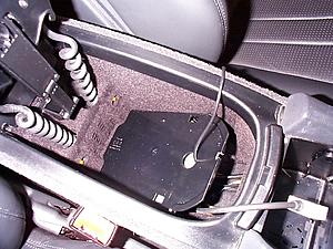
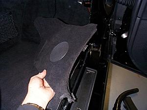
The I-Pod cradle will fit nicely in the lower center console, all that is needed is a small notch for the wire to pass through.

The console floor can go back in now.
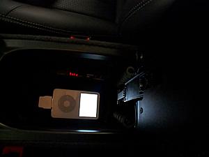
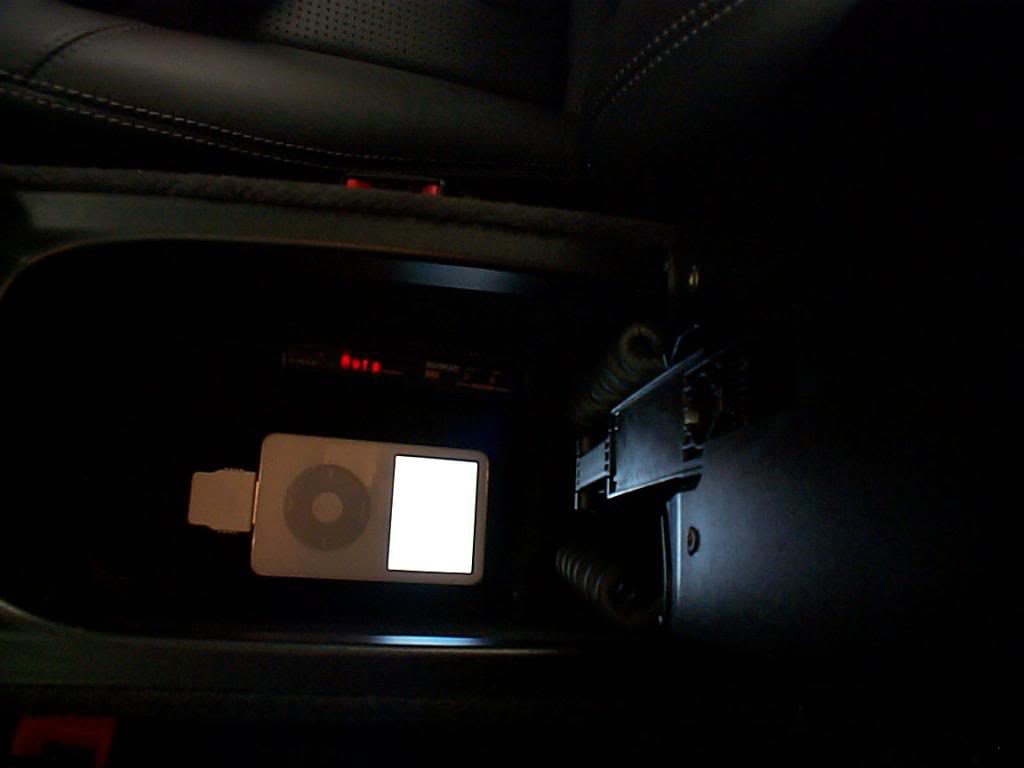
In and plugged in, I-Pod face lights up when click wheel is touched and has a MB star on the screen. The red "auto" is my Passport SRX controller.
Time to close up, on the down hill side now. Screw the CD magazine back in.
Plug in electric for ash tray and install.

Snap center gear shift surround back in place.
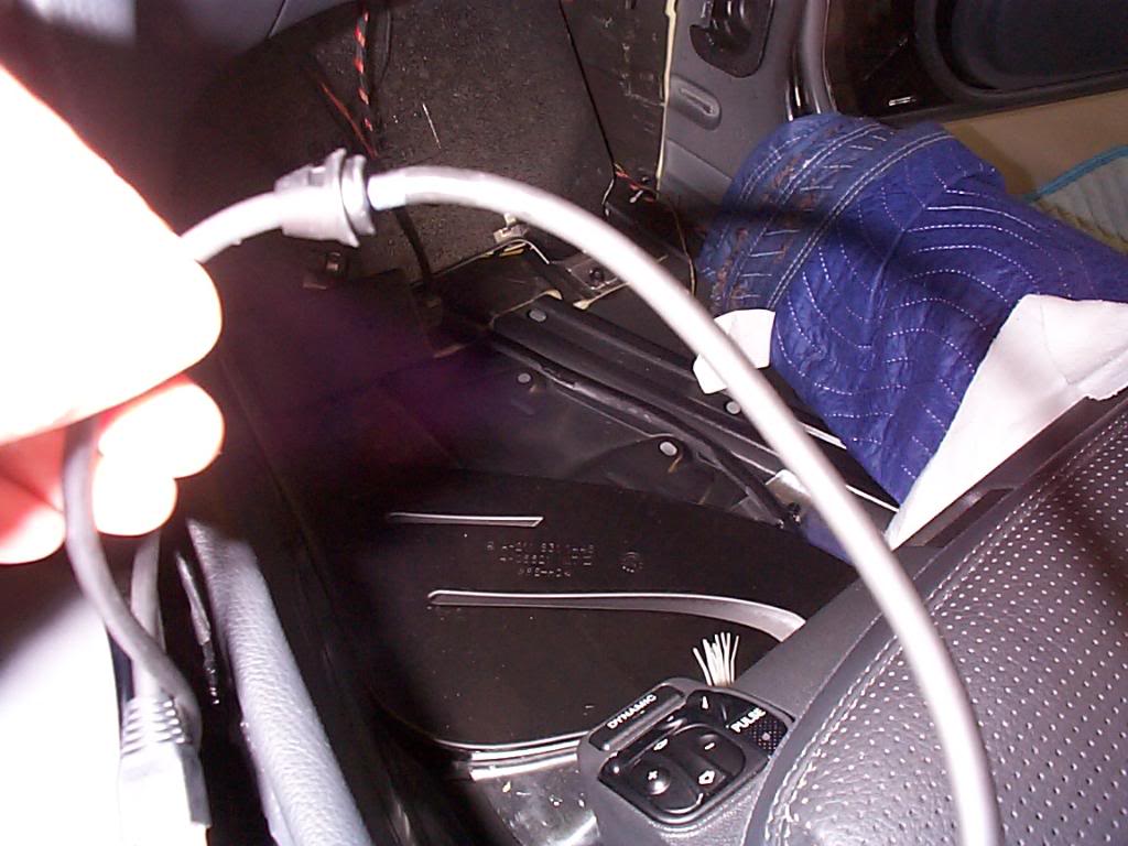
In case anyone was wondering what I was doing with my power wire. Here is where it passes through the fire wall. Upper right hand side of the foot well.
For now this is where I will terminate my power wire.
The carpet and foam goes in easier than it came out. Keep your wires for speaker and light out and above the carpet.
Reinstall kick panel don't forget to hook up speaker
The console floor can go back in now.

In and plugged in, I-Pod face lights up when click wheel is touched and has a MB star on the screen. The red "auto" is my Passport SRX controller.
Time to close up, on the down hill side now. Screw the CD magazine back in.

Plug in electric for ash tray and install.
Snap center gear shift surround back in place.

In case anyone was wondering what I was doing with my power wire. Here is where it passes through the fire wall. Upper right hand side of the foot well.

For now this is where I will terminate my power wire.

The carpet and foam goes in easier than it came out. Keep your wires for speaker and light out and above the carpet.
Reinstall kick panel don't forget to hook up speaker
Last edited by Yacht Master; 10-19-2008 at 06:55 PM.
10-18-2008 | 11:51 PM
#10
Thread Starter
MBWorld Fanatic!
Joined: Oct 2006
Posts: 3,642
Likes: 11
From: Caribbean/Florida/Colorado
E-ZGO 53hp., 1999 E 430 sport, 2004 E 55, 2008 Tahoe LTZ on 24"s
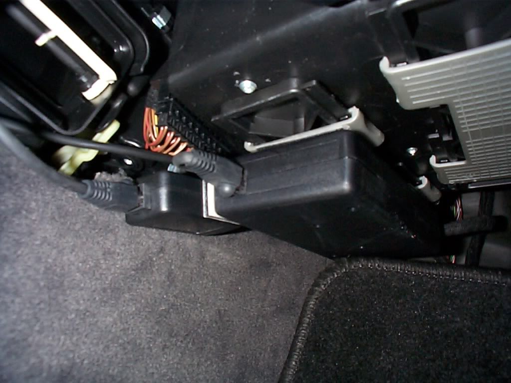
To make my interface install easy I used the Velcro strips to attach the interface to the plastic lock on the air filter door. I then cut out the white insulation on the finish panel, fit nice.
Replace the finish panel under glove box.
When you re fit the "B" pillar cover make sure to engage the seat belt hight adjuster.
Check for smooth operation of seat belt.
Install finish panel next to rear seat, you can set the clips with a large screw driver. Replace plastic nut and expanding rivet at base.
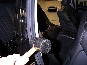
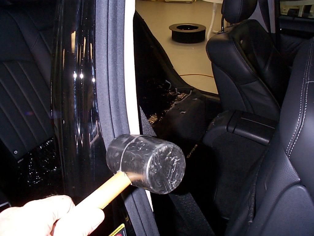
Replace the door / threshold seals, make sure the timing is same as when removed, use a clean dead blow hammer to get proper fit.
Replace rear seat.

Replace black Styrofoam in trunk.
Replace forward panel in trunk and then both side panels, and in my case spare tire and trunk floor.
Done, Total time including back ground reading 8 hours, Not a hard job but you do need a place to put everything when it is all apart. If I had to do it again it would be an easy 90 min job.

Replace the finish panel under glove box.
When you re fit the "B" pillar cover make sure to engage the seat belt hight adjuster.
Check for smooth operation of seat belt.

Install finish panel next to rear seat, you can set the clips with a large screw driver. Replace plastic nut and expanding rivet at base.

Replace the door / threshold seals, make sure the timing is same as when removed, use a clean dead blow hammer to get proper fit.
Replace rear seat.
Replace black Styrofoam in trunk.
Replace forward panel in trunk and then both side panels, and in my case spare tire and trunk floor.
Done, Total time including back ground reading 8 hours, Not a hard job but you do need a place to put everything when it is all apart. If I had to do it again it would be an easy 90 min job.
Last edited by Yacht Master; 10-19-2008 at 08:01 PM.


 10-19-2008 | 07:16 AM
#16
Super Member
Joined: Mar 2008
Posts: 695
Likes: 0
From: Delran, NJ
05 C55
now thats how you do a write up. has anyone used this setup ---> http://www.incartronics.com/
10-19-2008 | 12:15 PM
#17
MBWorld Fanatic!
Joined: May 2007
Posts: 1,763
Likes: 40
From: San Diego
2004 E55
now thats how you do a write up. has anyone used this setup ---> http://www.incartronics.com/
10-19-2008 | 02:13 PM
#19
MBWorld Fanatic!
Joined: Jun 2004
Posts: 1,880
Likes: 9
From: Seattle
05 E55
....OR, you can just plug in your iPod via the Aux in. 
Just Kidding. Thanks for the awesome right up and taking the time to take very good pictures for each step. I was just pricing one of the kits and now I feel confident to do it myself. You just saved me a lot of money.
Just Kidding. Thanks for the awesome right up and taking the time to take very good pictures for each step. I was just pricing one of the kits and now I feel confident to do it myself. You just saved me a lot of money.
10-20-2008 | 05:48 PM
#22
MBWorld Fanatic!
Joined: Sep 2005
Posts: 6,081
Likes: 211
From: Albuquerque
'07 GL320CDI, '10 CL550
For those with 2005-on W211, there's an MHI phone cradle for the iPhone.
There's a connection (pigtail) on this cradle to which you can connect a special new wiring harness that substitutes for the iPod connector in the glovebox. That is, you use the iPhone's, Ipod capability instead.
There's a connection (pigtail) on this cradle to which you can connect a special new wiring harness that substitutes for the iPod connector in the glovebox. That is, you use the iPhone's, Ipod capability instead.
Last edited by lkchris; 10-20-2008 at 09:35 PM.
 10-25-2008 | 09:58 PM
#25
Thread Starter
MBWorld Fanatic!
Joined: Oct 2006
Posts: 3,642
Likes: 11
From: Caribbean/Florida/Colorado
E-ZGO 53hp., 1999 E 430 sport, 2004 E 55, 2008 Tahoe LTZ on 24"s
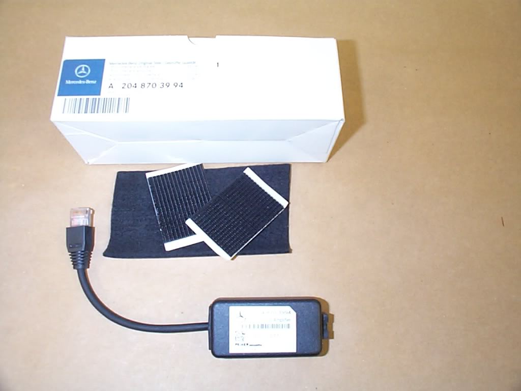
****Up Date******
This is the update to help overcome a difference in volume when you switch from CD to I-Pod or I-Pod to radio. It seems to be a in-line amp and will give louder play back and enhanced bass.
You can also check or change level by
#1. Turn on command.
#2. Select AUX/I-Pod.
#3. Press down arrow and Phone hang-up for 8 seconds.
#4. When VOL appears chose --- (down arrow) or +++(up arrow) Vol setting.
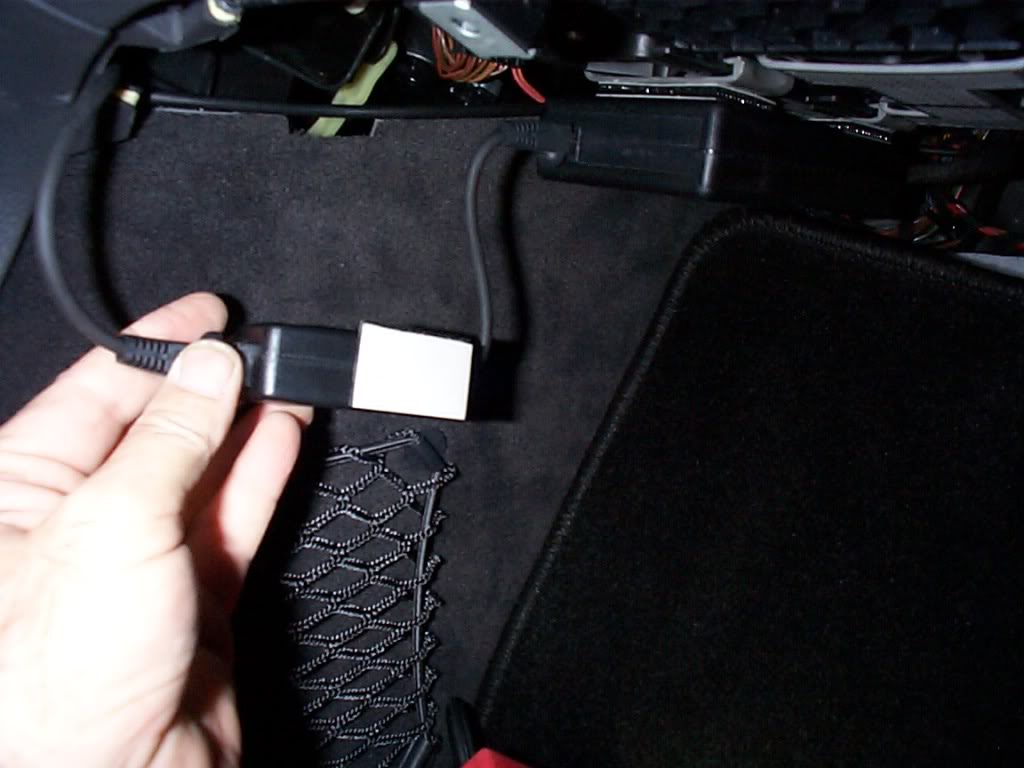
Here are the pics of install, simple Velcro 5 min job.

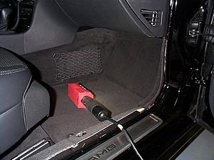
Remove passenger side panel below the glove box.
Un plug wire from I-Pod to interface and plug in, our new little amp.
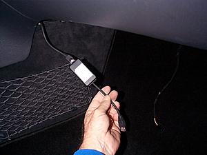
I cut the Velcro in half.
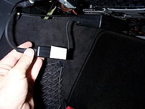
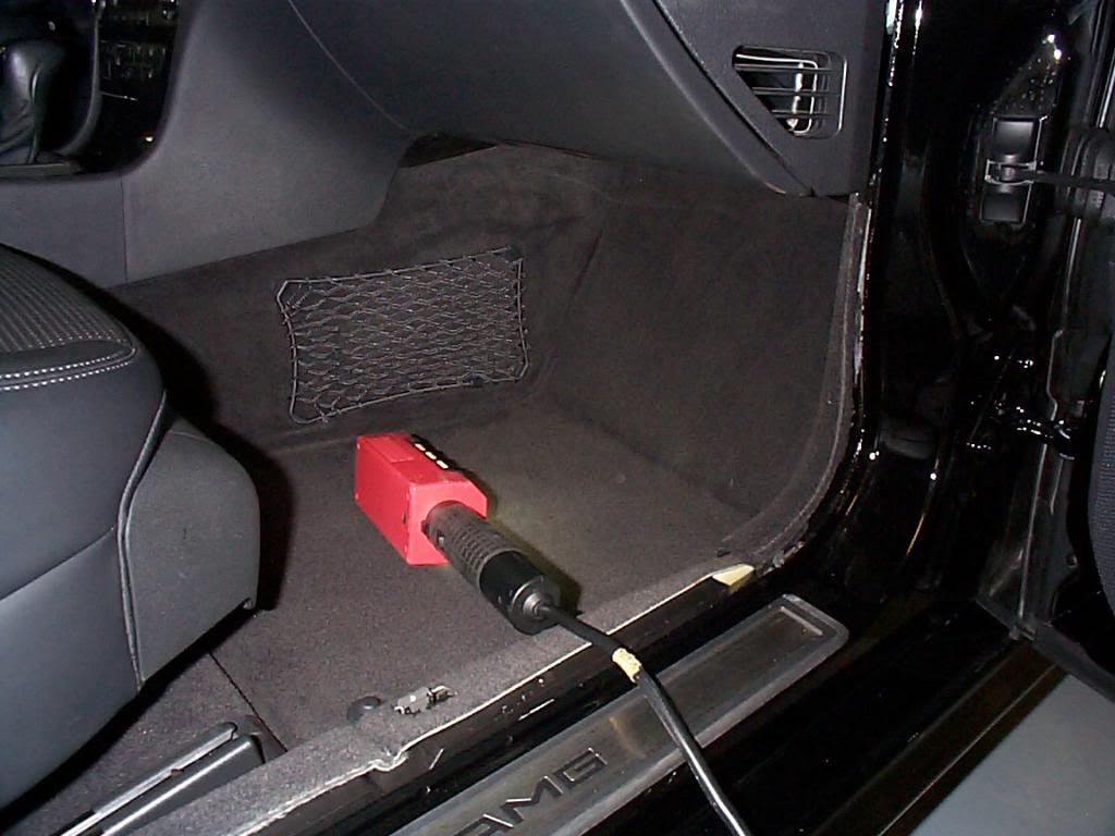
The Velcro will hold the line amp in place, and the upper foot well panel will support it.
You can also check or change level by
#1. Turn on command.
#2. Select AUX/I-Pod.
#3. Press down arrow and Phone hang-up for 8 seconds.
#4. When VOL appears chose --- (down arrow) or +++(up arrow) Vol setting.
Here are the pics of install, simple Velcro 5 min job.
Remove passenger side panel below the glove box.

Un plug wire from I-Pod to interface and plug in, our new little amp.

I cut the Velcro in half.
The Velcro will hold the line amp in place, and the upper foot well panel will support it.
Last edited by Yacht Master; 10-26-2008 at 07:58 AM.


