
S550 Night vision camera pin-out. Can someone point me in the right direction please?
Subscribe
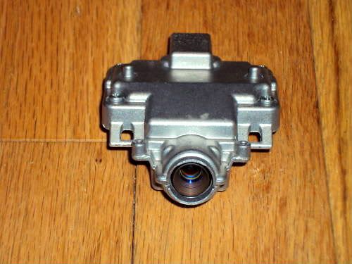
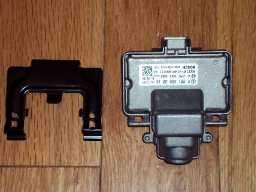
I am installing a S550 (W221) Night Vision camera and wonder if someone can point me in the right direction for the proper pinout for power and signal from the 10pin connector. Thanks in advance,
I checked startekinfo and WIS, and could not find any info...
I checked startekinfo and WIS, and could not find any info...
Diesel Benz
MBWorld Fanatic!
close

Today
- Join DateDec 2006
- LocationEurope
- Posts:6,498
-
iTrader Positive Feedback0
-
iTrader Feedback Score(0)
- Vehicle(s) I drive223.168 & 213.012 & 906.633 & 214.005
-
Likes:906
-
Liked:335 Times in 281 Posts
Quote:
You did check WIS, including documents like PE430P210399SAA?Originally Posted by andershoberg
I checked startekinfo and WIS, and could not find any info...
Quote:
Yes and I figured it was components. I have small RGB-composite and RGBVH -composite converters, so I can do this. My HUD will accept an component only, not composite. What do you think? Which ones are my power inputs and which ones are my video outputs? Here are the wiring details Originally Posted by Diesel Benz
You did check WIS, including documents like PE430P210399SAA?
Pin - description - wire color
1 - STK_L - BUWH
2 - STK_H - BU
3 - T-1L - OGWH
4 - T-1H - OG
5 - -CAM - BK
6 - Data-1H - GNWH
7 - Data-1L - GN
8 - Data-0H - RDWH
9 - Data-0L - RD
10 - +CAM - BKWH
Thanks in advance,

Junior Member
There is no video output pin as you might know it from analog systems. Data transfer is realized digitally, therefore you won't find a pin for video out.
Power supply is realized via pin 10 (+4.5V +-5%) and pin 5 (gnd).
Pin 1: control channel low, Input
Pin 2: control channel high, Input
Pin 3: clock low, Output
Pin 4: clock high, Output
Pin 5: Gnd
Pin 6: Data 1 high, Output
Pin 7: Data 1 low, Output
Pin 8: Data 0 high, Output
Pin 9: Data 0 low, Output
Pin 10: +4,5V
Quote:
Power supply is realized via pin 10 (+4.5V +-5%) and pin 5 (gnd).
Pin 1: control channel low, Input
Pin 2: control channel high, Input
Pin 3: clock low, Output
Pin 4: clock high, Output
Pin 5: Gnd
Pin 6: Data 1 high, Output
Pin 7: Data 1 low, Output
Pin 8: Data 0 high, Output
Pin 9: Data 0 low, Output
Pin 10: +4,5V
\Originally Posted by cc4469
There is no video output pin as you might know it from analog systems. Data transfer is realized digitally, therefore you won't find a pin for video out.Power supply is realized via pin 10 (+4.5V +-5%) and pin 5 (gnd).
Pin 1: control channel low, Input
Pin 2: control channel high, Input
Pin 3: clock low, Output
Pin 4: clock high, Output
Pin 5: Gnd
Pin 6: Data 1 high, Output
Pin 7: Data 1 low, Output
Pin 8: Data 0 high, Output
Pin 9: Data 0 low, Output
Pin 10: +4,5V
Thanks for your reply.
Is this Mercedes proprietary? It looks a little bit like a simplified HDMI...
Anders
Junior Member
Anders,
to be honest, I don't know if it's proprietary or not. It's not HDMI, but LVDS (see wikipedia).
Greetings,
CC
to be honest, I don't know if it's proprietary or not. It's not HDMI, but LVDS (see wikipedia).
Greetings,
CC


Are you retrofitting night vision?


