When you click on links to various merchants on this site and make a purchase, this can result in this site earning a commission. Affiliate programs and affiliations include, but are not limited to, the eBay Partner Network.
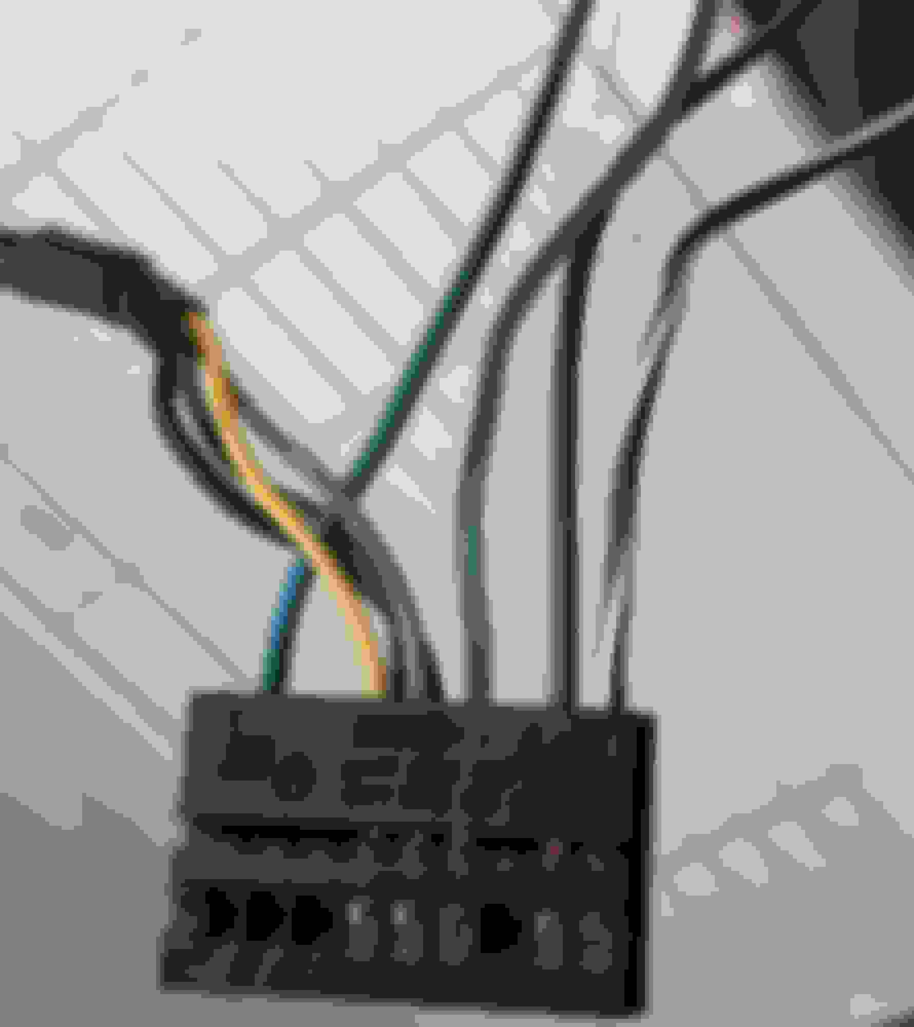
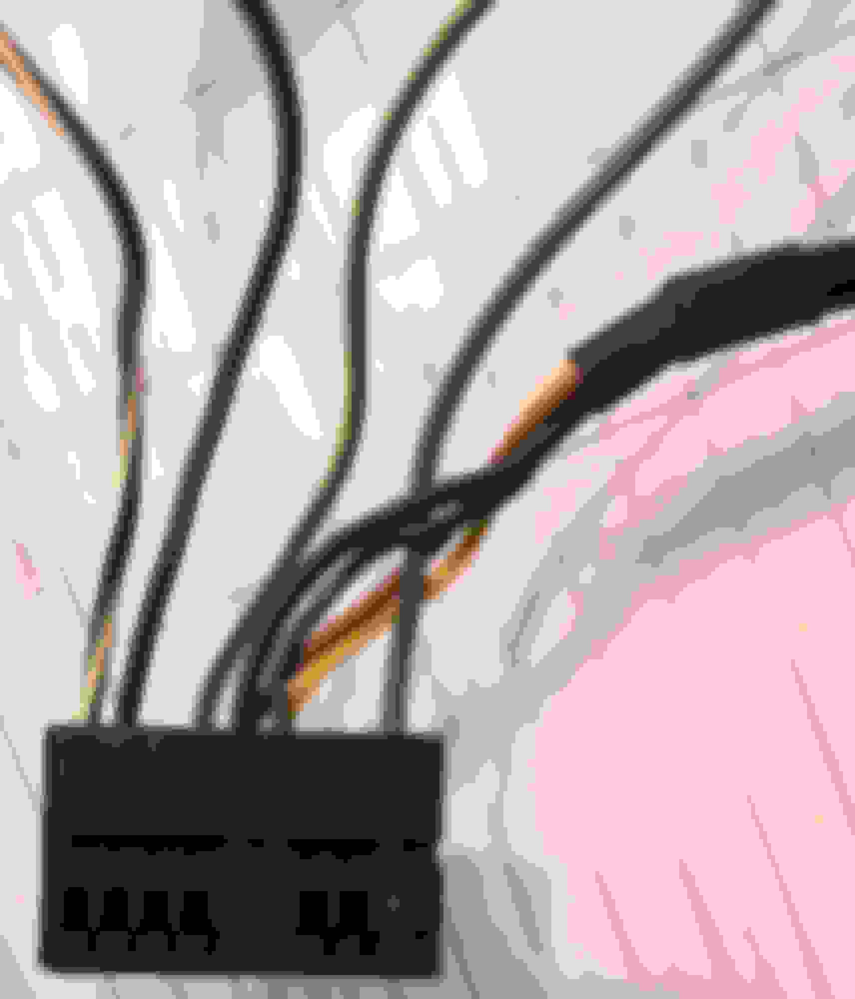
My clk430 had an aftermarket pioneer radio installed when bought, I have recently updated the radio with another pioneer and hope to get the steering wheel buttons to function using the PAC - SWI interface box. I have found that most of the original wiring has not been too messed around with and have identified what I believe is the C2 connector used on the command 2 radio which I'm assuming was an option on this car. The pictures show the connector with the housing removed to identify which coloured wire goes to which pin
Pin 4 yellow, pin 5 brown, pin 6 green with black stripe, pin 8 black, pin 9 black with white stripe, pin 10 blue, pin 13 black and pin 14 black
Some of the online pinout sites have pin 4 as aux in right, pin 5 as aux in ground, pin 6 as speedsensor, pin 8 as can bus low, pin 9 as can bus high, pin 10 as D2B wake up, pin 13 as aux in left, pin 14 as aux in ground.
Can anyone confirm these are correct because I thought most of the can bus wires are brown, and brown and red. I don't have a wiring diagram for a CLK 430 a208 for the radio which would help a lot. Grateful for any help.
Mercedes SLR McLaren 722 S Is Extremely Rare Example Modified by McLaren
Slideshow: A one-of-one U.S.-spec Mercedes-Benz SLR McLaren Roadster became even rarer after a factory-backed transformation at McLaren's headquarters.