When you click on links to various merchants on this site and make a purchase, this can result in this site earning a commission. Affiliate programs and affiliations include, but are not limited to, the eBay Partner Network.
Hello, Not even sure if this is still going but did anyone attempt this on a E320 cdi 2001 w210? Vacuum system still the same as this, just unsure of the wires i need to tap into. Any help appreciated!
Hi Lancelot. Thank you very much for your detailed explanation. I did everything what you expalined on my mercedes benz w202 c220 cdi 1999. First 2-3 minutes after starting engine everything is perfect. Car is gong well, black smoke is reduced but after some time car goes limp home mode. After disconnecting maf again everything is good. But I dont understand why car goes to limp home mode with maf connected. Before I faced the problem like this that is why I know that when car goes home mode it needs to disconnect maf. At that time priblem was that egr valve didn't work so maf put the engine to home mode.
Hi Guys,
W210 E Class 300TD
Bought my resistors and diode and just about to perform what seems from the posts an easy fix and I have some challenges.
Questions
The fattest module where all the computers are is the ECU? YES/NO
If so then there's three yellow and white wires in the ECU. Only one has two white stripes on it and that connects to pin 5 on the MAF.
When I try and test the MAF pin 5 (yellow and white wire), I can only do that by unplugging the connector to the MAF, Connecting my multitester to pin 5 and the other connection to earth. I get no voltage what so ever even if I rev the car... According to the above I should get 12volt ish and a drop of 4 or 5v when reved. This I am not seeing....
Can anyone help?
Thanks
Chris
When looking for the plug number, or is it pin number, it starts from the wing of the car, not the engine side, easy mistake to make.
But at which end of the connector? He He. That's my question seeing as how I can't get the yellow and white wire to give any voltage signal ay the MAF, I must try and count the pin number on the ECU connector. I have a '98 W210 E Class 300TD which this mod was orginally for? I should have a little faith and just go for it but I like the thread suggests, I need to be sure before I go spilcing in ciruitry to my lovely car's ECU.
Thanks anyone that can help further.
Chris
Hi,
I've had a reply on one of the forums I’ve been enquiring about this on. Thanks for the replies… I have a W210 E Class 300TD early '98. I eventually managed to detect some sort of signal with the MAF plug undone. Think it was impedance or Amps. When the car revved, the signal dropped. I then undid the ECU plug and tried to count the pin numbers and could come to no reasonable conclusion. The pin numbers were very different on the ECU end compared to what is on the thread. However, I left the MAF plug out and tested for the same signal at the ECU end once the ECU it was plugged was plugged in minus its outer mechanism. The same signal was detected on the Yellow wire with two white stripes. There's two other yellow wires with single white stripes. Beware! There is only one green and grey wire but there's a grey and pale purple wire which looks very similar. Beware!
Once the resistor and diode were in place I reset the gearbox ECU (easily done via YouTube video) and it’s been running very, very strong with less turbo lag. I can use the kickdown button with confidence now and only a minimal puff of smoke when jacked. Very happy with the result. Many thanks to all who made this possible and other reassuring me it was possible and I wouldn’t screw my ECU…
Chris
Reason I am posting is that I spliced in the resistor and diode into the ECU wiring to bypass the EGR and the car ran like a dream. The last couple of days I noticed that the EGR problem was back or whatever it is... I actually died on a hill when the car was cold. I’ve respliced in new components and will have to see. I did the amended version where only a 470 ohm resistor and one diode is used. No 1000 ohm added. Anyone else had problems with this and the EGR still trying to function with this MOD?
Hi Guys,
Just thought I've spliced the resistor and the diode only into the ECU harness, yet I still have the EGR transducer vacuum hose connected to the EGR valve. Do I need to disconnect the vacuum hose?
Chris
New on this forum. Can someone assist on how to delete EGR valve on my W203 C270 CDI with pics
It should all be on this thread. The main challenge is getting the right wires at the ECU end. I would think you car probably works in the same way. There's also other information on YouTube and other Merc. forums.
Have fun
Chris
I tried this MOD last year and it is not until recently have I realised that the suction pump is still operating the EGR. This MOD reads that you leave everything connected to the EGR -as I did - however, the EGR has still been causing problems and here's me thinking it had been deleted from operation. I have stripped and resoldered the exact diode and resistor to the exact wiring. I left out the original last resistor as this MOD says it is surplus to requirements. I would not have attempted this if I was unsure. Also I've worked on cars for over 35 years. I am no spring chicken. Everything was checked and re-checked?
Do I now assume that I can disconnect the suction pump and it will not throw out a error. I tried blocking the suction pump vacuum line with melted wax and it threw out an EPC Engine Electronics error until I allowed the pump to suck again.
You took the bait. All those saps that thought they were accomplishing something,actually accomplished nothing,except screwing up their wiring and falsely thinking they fooled the ECU---FYI the EGR only functions when the engine coolant temp is below running conditions-----what do you really gain????
So not even using the MOD that uses two resistors and the diode works? Surley it's not all a big load of rubbis? The logic makes sense... There are commercially made boxes that are made for this too. This has had so much coverage over a few forums and they all seem to agree that it works... Are you just a natural sceptic or is this the words of a very wise person? The EGR recirculates all the time, thats the problem... It can get stuck open any time and has. Even on a long journey. with a properly working thermostat the coolant is hovering around the engine temperature anyway isn't it?
Hey Biff this is the W210 forum and although open to posting all sorts of helpful hints, misinformation and HS sometimes creeps in----go back to the original post and follow the OP's directions,but don't start whining if you have problems with your 19 year old rust bucket----ever think of starting to save for a newer car!
Hey, I must have noticed this a while back as the post above are mine and I nearly replied to one of my own. Just to be sure, the reason a run my 20 year old NOT RUST BUCKET as it is probably the best example in the UK, is beucase it is also smoother than any new car and is a complete pleasure to drive. It can be worked on, and things mended/serviced and put back on. Its a very environmentally sound car as it doesn't have disposable parts.. I choose to drive it daily... It so reliable its never let me down and this is the second one of these I've had... I've had many a car in my time including a 1967 mustang. I prefer this type. And yeah, it's got acres of wood and room.
I tried this, didn't work and may hitherto unidentified deleterious effects. I would bother plus it is important to have the EGR for emissions for a UK MOT. The only test Mercedes do is put a vacuum line on the EGR. Once opened, if it snaps shut, that is good enough for Mercedes so it is good enough for me.
Chris
Disclaimer: READ people! This article is a compilation/summary of posts on UK-based MB owners forums. All credit goes to 'Dieselman' and 'Oygle' there! Please DO NOT PM me about if this works on car 'X' or petrol engines. I simply do not know!!! I did the below mod to my own car and it works. I DO NOT want to invest any more time and effort in it so please work with the info below. You do this mod at YOUR OWN RISK!!! Neither me, MBWorld.org, or anyone other than YOURSELF can be held responsible for seriously damaging the electronic systems in your car if you don't know what you're doing!!! And before replying, PMing: please READ...people!
__________
Mod to disable the EGR on DIESEL engines.
In general it's felt that having the EGR (ExhaustGas Recirculation) system on DIESEL engines is good for reducing the NOX output but bad in all other respects. It reduces economy, creates more smoke, increases problems and maintenance requirements due to clogging the intake and can reduce overall engine life. As a result of wanting greater economy many owners want to stop the exhaust gas being recirculated. The problem with doing this on a modern engine is that the EGR valve operation is monitored by the Engine Computer (ECU). The only way to disable the EGR and not trip a fault code and limp home mode is to fool the ECU into thinking the EGR is still working.
This mod works on earlier TurboDiesel and CDI cars with a vacuum-controlled EGR valve. Check to see if your EGR-valve ONLY has a vacuum-hose connected to it�s BODY.
(If the actual EGR-valve BODY has an electrical connection this mod won�t work...)
Skills involved are sorting out wires, using a multimeter and handling a soldering iron...
Pros:
- Less sooth output
- Less CO2 output
- No more �sooth/grease/gunk�- buildup in the inletmanifold (choking the engine)
- Smoother and quieter running engine
- Fuel economy improves around 2%
Cons:
- NOX output increases
- On CDI engines, warmup time increases. CDI�s have an exhaustgas/coolant-heatexchanger shunted through EGR operation. Take it easy the first few miles (like you should anyways!)
How does it work?
The Engine Computer (ECU) measures intake airflow using the Mass Air Flow sensor (MAF). This MAF is situated in the airstream right behind the airfilter box. When the EGR-valve is opened, a portion of the exhaust gasses are sucked directly into the inlet manifold (further downstream) so the ECU measures a slight drop in airflow through the air filter box. (the MAF puts out a slightly lower Voltage signal)
When removing the vacuum-hose for EGR-operation, or blocking off the EGR valve, the ECU does not measure the slight drop of airflow on the MAF when it operates the EGR and eventually throws an error code and puts the car into limp-home-mode! The ECU will also limp the car when it does not �see� the EGR transducer. (This tranducer controls the vacuum to operate the actual EGR-valve)
The Modification:
A small circuit (consisting of two resistors and a diode) is hooked-up to the wiring harness going to the ECU. One 1kΩ resistor acts as (the load of) the EGR transducer. Another 470Ω resistor in series with a 1N4004-diode utilizes the control signal for EGR operation to pull the Voltage drop the ECU expects to see on the MAF-signal. That�s all! The ECU is fooled, and the engine still gets the same amount of airflow but it�s all clean air coming through the inlet, getting full boost!
The EGR-transducer can now simply be unplugged. This causes the EGR-valve to stay closed at all time. That�s it! No clipping of wires and everything still looks original under the hood. For emissions testing, if needed you can simply connect the EGR-transducer and unplug it again when passed!!!
Making the circuit:
1/4 watt resistors are fine as there is no current, just signal voltage.
First identify your components. L-R = diode, 470 ohm and 1000 ohm resistors.
Solder the 470 ohm resistor to the tail of the diode. Note the silver band on the diode shows which is the + positive blocking.
Add the 1k ohm resistor to the other end of the diode and add appropriate wire then clip off any stray tails.
Fit heatshrink tubing to the bare sections.
And then tape over with material tape for protection to complete.
(The Red wire is +12v, Yellow is MAF, Green is EGR transducer signal.)
Hooking it up to the car:
Please - everyone doing this Mod. DON'T take wire colours for granted. All models are different.
Locate the appropriate wire at the MAF using a simple voltage meter. Look for the wire at the maf that indicates a Voltage change in the range of 2 to 4 volts approx. when the engine is Revved. When you have located the wire, note the colours and find the same wire near the ecu. The 12 Volt power source at the ecu of the 300TD is easy to find, once again with a meter, and the wire at the EGR transducer is also simple to locate, once again note the colour at the unit and find it again near the ecu. This is the only failsafe procedure!!!
Below are the known connections for W210 300 TurboDiesel and W210 270CDI, W210 320CDI and W163 ML270 CDI.
EGR transducer negative side:
300 TD: Pin 35 (grey-green wire)
CDI: Plug 3, Pin 50 (grey-black wire)
EGR transducer positive side:
300 TD: Any pin/wire that has switched +12V
CDI: Plug 3, Pin 37 (grey-red wire)
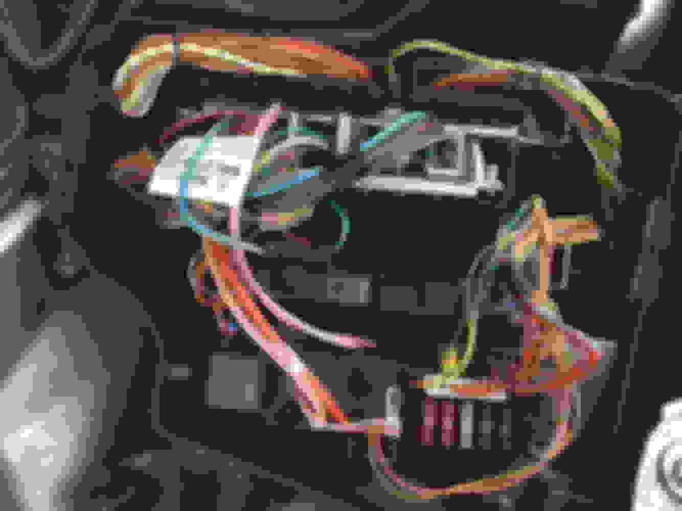
Inside the ECU box:
Hook up the circuit inside this box. It will be insulated and safely dry there!
Good luck!
A next project will be taking off my inlet manifold and clean out all the gunk that's probably inside. Below a pic of the inlet channels on a OM613 320CDI after 300k KM's...
Hi
Where are the pictures?
Can you sent me the pictures ?
Disclaimer: READ people! This article is a compilation/summary of posts on UK-based MB owners forums. All credit goes to 'Dieselman' and 'Oygle' there! Please DO NOT PM me about if this works on car 'X' or petrol engines. I simply do not know!!! I did the below mod to my own car and it works. I DO NOT want to invest any more time and effort in it so please work with the info below. You do this mod at YOUR OWN RISK!!! Neither me, MBWorld.org, or anyone other than YOURSELF can be held responsible for seriously damaging the electronic systems in your car if you don't know what you're doing!!! And before replying, PMing: please READ...people!
__________
Mod to disable the EGR on DIESEL engines.
In general it's felt that having the EGR (ExhaustGas Recirculation) system on DIESEL engines is good for reducing the NOX output but bad in all other respects. It reduces economy, creates more smoke, increases problems and maintenance requirements due to clogging the intake and can reduce overall engine life. As a result of wanting greater economy many owners want to stop the exhaust gas being recirculated. The problem with doing this on a modern engine is that the EGR valve operation is monitored by the Engine Computer (ECU). The only way to disable the EGR and not trip a fault code and limp home mode is to fool the ECU into thinking the EGR is still working.
This mod works on earlier TurboDiesel and CDI cars with a vacuum-controlled EGR valve. Check to see if your EGR-valve ONLY has a vacuum-hose connected to it�s BODY.
(If the actual EGR-valve BODY has an electrical connection this mod won�t work...)
Skills involved are sorting out wires, using a multimeter and handling a soldering iron...
Pros:
- Less sooth output
- Less CO2 output
- No more �sooth/grease/gunk�- buildup in the inletmanifold (choking the engine)
- Smoother and quieter running engine
- Fuel economy improves around 2%
Cons:
- NOX output increases
- On CDI engines, warmup time increases. CDI�s have an exhaustgas/coolant-heatexchanger shunted through EGR operation. Take it easy the first few miles (like you should anyways!)
How does it work?
The Engine Computer (ECU) measures intake airflow using the Mass Air Flow sensor (MAF). This MAF is situated in the airstream right behind the airfilter box. When the EGR-valve is opened, a portion of the exhaust gasses are sucked directly into the inlet manifold (further downstream) so the ECU measures a slight drop in airflow through the air filter box. (the MAF puts out a slightly lower Voltage signal)
When removing the vacuum-hose for EGR-operation, or blocking off the EGR valve, the ECU does not measure the slight drop of airflow on the MAF when it operates the EGR and eventually throws an error code and puts the car into limp-home-mode! The ECU will also limp the car when it does not �see� the EGR transducer. (This tranducer controls the vacuum to operate the actual EGR-valve)
The Modification:
A small circuit (consisting of two resistors and a diode) is hooked-up to the wiring harness going to the ECU. One 1kΩ resistor acts as (the load of) the EGR transducer. Another 470Ω resistor in series with a 1N4004-diode utilizes the control signal for EGR operation to pull the Voltage drop the ECU expects to see on the MAF-signal. That�s all! The ECU is fooled, and the engine still gets the same amount of airflow but it�s all clean air coming through the inlet, getting full boost!
The EGR-transducer can now simply be unplugged. This causes the EGR-valve to stay closed at all time. That�s it! No clipping of wires and everything still looks original under the hood. For emissions testing, if needed you can simply connect the EGR-transducer and unplug it again when passed!!!
Making the circuit:
1/4 watt resistors are fine as there is no current, just signal voltage.
First identify your components. L-R = diode, 470 ohm and 1000 ohm resistors.
Solder the 470 ohm resistor to the tail of the diode. Note the silver band on the diode shows which is the + positive blocking.
Add the 1k ohm resistor to the other end of the diode and add appropriate wire then clip off any stray tails.
Fit heatshrink tubing to the bare sections.
And then tape over with material tape for protection to complete.
(The Red wire is +12v, Yellow is MAF, Green is EGR transducer signal.)
Hooking it up to the car:
Please - everyone doing this Mod. DON'T take wire colours for granted. All models are different.
Locate the appropriate wire at the MAF using a simple voltage meter. Look for the wire at the maf that indicates a Voltage change in the range of 2 to 4 volts approx. when the engine is Revved. When you have located the wire, note the colours and find the same wire near the ecu. The 12 Volt power source at the ecu of the 300TD is easy to find, once again with a meter, and the wire at the EGR transducer is also simple to locate, once again note the colour at the unit and find it again near the ecu. This is the only failsafe procedure!!!
Below are the known connections for W210 300 TurboDiesel and W210 270CDI, W210 320CDI and W163 ML270 CDI.
EGR transducer negative side:
300 TD: Pin 35 (grey-green wire)
CDI: Plug 3, Pin 50 (grey-black wire)
EGR transducer positive side:
300 TD: Any pin/wire that has switched +12V
CDI: Plug 3, Pin 37 (grey-red wire)
Inside the ECU box:
Hook up the circuit inside this box. It will be insulated and safely dry there!
Good luck!
A next project will be taking off my inlet manifold and clean out all the gunk that's probably inside. Below a pic of the inlet channels on a OM613 320CDI after 300k KM's...
proper way is to get the ecu reprogrammed with no egr $200
Mercedes SLR McLaren 722 S Is Extremely Rare Example Modified by McLaren
Slideshow: A one-of-one U.S.-spec Mercedes-Benz SLR McLaren Roadster became even rarer after a factory-backed transformation at McLaren's headquarters.


 strato80@orange.fr