When you click on links to various merchants on this site and make a purchase, this can result in this site earning a commission. Affiliate programs and affiliations include, but are not limited to, the eBay Partner Network.
I don't know about a software method, but you could always wire up a timer relay. I would be worried about going past 2 hours (available in the stock rom) as it may drain your battery.
Good idea. My concern would be leaving the HU fully on for very much time after killing the engine. The 'shutdown delay' puts the unit into a standby/sleep mode for a period of time, which I assume draws a lot less current.
I have a Newsmy Android head unit in another car. It has a lot more variability in the shutdown delay. I have it set up for 48 hours. It works great, and I've never had any issues with the battery. I assume the current draw in standby mode is fairly minimal.
It would be great if there was a modified MCU out there that has the shutdown delay options expanded to include longer periods of time.
Does anyone know of a diagram or something where I can find where the reverse light power wiring is? Or do I just have to trace the wire from the bulb.
I am in the process of installing an 8.8"(9") display HU in my 2009 CLS 63 AMG. The HU is the same as the one Seicane sells, but I found it on AliExpress. Unfortunately, it's harness is really designed for 2006-2008 CLS's. So, it turns out that the harness does not match up.(probably because my unit is an NTG 2.5, and the harness was made for a prior version)
I am in the process of installing an 8.8"(9") display HU in my 2009 CLS 63 AMG. The HU is the same as the one Seicane sells, but I found it on AliExpress. Unfortunately, it's harness is really designed for 2006-2008 CLS's. So, it turns out that the harness does not match up.(probably because my unit is an NTG 2.5, and the harness was made for a prior version)
So, I'm just wiring it up manually. I found th
Hi Xpression,
It looks like you might have been responding to my post, but your response must have gotten cut off for some reason.
Yeah the website was playign games with me and would not let me quote, so i re typed my response 4 times and spend over 40 minutes trying to respond to only have it hang and not actually post and i lose everything so i got frustrated and gave up. I will reply back shortly, just really snowed down with jobs and weather here in AUST is shocking atm .
Sorry but i will get back to you and everyone else for that matter.
[QUOTE=pfarley11;6925352]
Originally Posted by Xpresion
Hi Xpression,
It looks like you might have been responding to my post, but your response must have gotten cut off for some reason.
[QUOTE=Xpresion;6926005]Yeah the website was playign games with me and would not let me quote, so i re typed my response 4 times and spend over 40 minutes trying to respond to only have it hang and not actually post and i lose everything so i got frustrated and gave up. I will reply back shortly, just really snowed down with jobs and weather here in AUST is shocking atm .
Sorry but i will get back to you and everyone else for that matter.
No worries. Sorry about the trouble with the website.
By the way, I have one other question related to installation for you or anyone who might know.
I installed the 9" display HU (AliExpress, same as the Seicane 9" HU) in my 2009 CLS 63 AMG. It works great, but I have one problem: I am not able to get the steering wheel controls to work with the device.
I was not able to use the original HU connector(HU to OEM stereo connector) provided with the HU because my car is a 2009 with the NTG 2.5. I believe the HU connector was actually intended for a 2006-2008 CLS. So, I had to connected each wire separately. It all works great except for the steering wheel controls.
For the steering wheel controls, I connected the green/black wire to CANBUS High, and I connected the green wire to CANBUS Low. Also, I configured the CANBUS interface box for B200.(although I tested every combination, I believe) I think I did this all correctly, but I am not able to program(learn) the steering wheel buttons. It appears that the CANBUS box is not recognizing the CANBUS signals.
Do you know what I might have done wrong? Or, is it possibly a problem with my CLS being a 2009 model, instead of 2006-2008? Is there possibly a difference between the '09 CANBUS protocol and prior years?
Or, do I need to have the car set to non-COMMAND by a Star Diagnostic machine before this will work? (just guessing)
From memory it may be a grey colour or white with red. However the best and easiest way to find the wire is to have the cay in key pos 2 but not running! and then apply your foot on the brake and put the shifter in R position then go to the boot with the multi meter and see which wire is showing +12v
Originally Posted by Dnasty
Does anyone know of a diagram or something where I can find where the reverse light power wiring is? Or do I just have to trace the wire from the bulb.
I am not sure why someone would want standby to go for that long really, 1 minute in the morning and after work waiting for the head unit to boot up is not that much of a problem, much better then having the unit on standby for over 24 hours still drawing (minimal) current. this will just cause the battery to always needing to be charged by the charging system. i honestly don't see the point.
it may just be easier to just buy the Remote start from Midnight city Engineering and do your car good by remote starting it and letting it warm up while also and also giving the stereo time to boot up and be ready for you when you enter the car.
Originally Posted by pfarley11
Good idea. My concern would be leaving the HU fully on for very much time after killing the engine. The 'shutdown delay' puts the unit into a standby/sleep mode for a period of time, which I assume draws a lot less current.
I have a Newsmy Android head unit in another car. It has a lot more variability in the shutdown delay. I have it set up for 48 hours. It works great, and I've never had any issues with the battery. I assume the current draw in standby mode is fairly minimal.
It would be great if there was a modified MCU out there that has the shutdown delay options expanded to include longer periods of time.
Again, i think i covered that before mate, take the unit out and remove the tiny chrome screws that are holding the face of the screen, you will notice a think delicate looking black and red pair cable which is for the microphone, cut the red side and tape it up. now when you use the external mic , all should be great. I have tested this on many units and get the same result.
Originally Posted by tubaprde
did you have to modify anything or adjust the settings on the HU to get good bluetooth call quality? i'm still having major issues with mine....echos on the other end
OK allot of stuff in this, so i am not sure whats been resolved already and whats not.
To start off with, the RCA to Optical fiber method that people are oping in for has no support from the manufacturers. that's why wiring is showing to be a hassle to all. better off using the 6M cable and know that the unit is wired correctly.
Can H and CAN L hare polarised, so they need to be connected the correct way otherwise no communication is possible.
The RED + and PINK + are supply power to the ORIGINAL unit, however the unit utilizes these according to certain circumstances, i think powering the unit on when there is no key in the ignition. again this is all regulated via canbus. and its not available for the after market units. unless the manufacturers decides to add this condition tot he canbus decoder. which seems too difficult and they just don't bother.
the 3 UNKNOWN cables are actually for the AUX input in the glove box. I rewired it to the AUDIO RCA INPUT of the android unit so that i can still get AUX input. i will never use it but i like to know that everything is working / connected in teh car
lastly, DONT ignore the canbuss, its critical for the operation of the system and features. you are not installing a dumd SONY /Alpine stereo in there. you are installing something that requires constant communication with the car so it determines when when the car is in Reverse gear, when the lights are on so it power on illumination/ when when to shut down (after the door is open) etc etc
Originally Posted by nordicbenz
Reading this thread, and other threads, everybody talks about the CANBUS taking care of waking up the Head-Unit, reverse camera, illumination, etc etc. But nobody seem to mention how to locate the CAN wires on the power adapter and actually connecting them to the cars CANBUS. I realize now this is because most have the Benz ISO harness adapter making connecting CANBUS and power and everything easy. Kinda surprised not more people have been facing the same issues as me. CAN-wires are not marked on my power adapters.
After doing some more research, and I found the CAN-B hub under the left side carpet/rocker.
Canbus hub left carpet with rocker
But then I read in this thread that you can splice into the brown + brown/red wires connected to the CH-changer, for CANBUS connection, I assuming these are the ones here?
CANBUS wires located on CD changer connector
I received two power adapters with my Head Unit, and I am not sure which of them to use. The Canbus decoder is connected to one of them, but can be connected to the other as well. Probably it does not matter which I use.
My two power adapters
Anyway using this scheme, I managed to locate CAN-H and CAN-L on one of my adapters.
Layout of Benz ISO harness plug/adapter
Layout of Benz ISO harness plug/adapter
Seem like CAN-H is the green/black and CAN-L is the green. And these green cables are the only ones going from the large Benz Harness connector to the connector for the Canbus adapter, so it makes sense these are in fact the CAN-H and CAN-L. (how hard was it for the seller to just mark these cables? - instead of assuming everybody has the Benz ISO harness)
Power adapter 1 - Location of CAN-H / L on Benz ISO harness plug/adapter
Power adapter 1 - Location of CAN-H / L on Benz ISO harness plug/adapter
Power adapter 2 - Location of CAN-H / L on Benz ISO harness plug/adapter
Now, for CANBUS connection, I am assuming I connect the green/black wire from the power adapter to the brown/red cable going to the CD changer. And the green to the brown.
Can I destroy the Canbus or any devices in my car if I am wrong?
For constant +12 and GND to the Head Unit and optical adapter, I can connect to the wires already powering my old COMAND APG. Or should I use power from the ash tray as they look thicker?
And I am guessing it should not matter which of the power adapters I use, since I will not be connecting to the Benz ISO Harness side anyway.
There is however a difference between them in how they are pre-wired.
One of them has the WHITE wire from the HU connected to the WHITE wire of the Canbus Decoder. The other one has the BLUE wired from the HU connected to the WHITE wired on the Canbus Decoder. I have no way to know what these connections do as I have not succeeded to find pin-outs for any of the sides.
My two power adapters
Sorry to see the attached images being blow up even if I had downsized them, but that is another story.
If the Optical loop is broken all devices go into sleep / standby mode until they detect Optical signal again. so always be sure to continue the loop and never break it! if you must then remove the optical cables from the connector (they are just clipped in the connector) and now get your self (Vacuum hose / Window washer hose) YES YOU READ THE CORRECTLY! and now cut about 3 cm of it and terminate the 2 optical fiber ends inside. and push them as deep as possible so they meet in the middle. this will cause the optical signal to continue without being corrupted by ambient light
Originally Posted by depoteet
My CLS is a 2006, so I'm not sure if we have the same thing. I have an android head unit and I purchased a MOST Interface from AVIN. At first I didn't get sound and it turned out the problem was that I had disconnected the CD Changer which broke the fiber loop. Once I realized what I had done (I work fiber in IT but didn't realize there was only one fiber path for all devices in the car that are fiber connected) I reconnected the changer and great sound.
Earlier I had some issues figuring out power for the head unit itself. I needed an Aux, light, and switched power. Oh and the AVIN MOST interface needs an unswitched always on power connection.
To me it sounds like its the the canbuss decoder is not correct.
FYI you wont be able to reassign or learn the steering wheel buttons using the app thats on the unit. its just not possible because the canbuss box perform that passively. I tested those 9" units and not a fan. too many issues which i did not like.
From memory the canbus decoder the used was slightly different and it had din switches on the side where you can select the type of car ? have you tried adjusting that? after every adjustment you need to reset the canbus by powering off the car and back on.
Finally, have you tried changing the canbuss protocol within the FACTORY SETTINGS int he unit and entering the password (126) ?
Regards
[QUOTE=pfarley11;6926401]
Originally Posted by Xpresion
Yeah the website was playign games with me and would not let me quote, so i re typed my response 4 times and spend over 40 minutes trying to respond to only have it hang and not actually post and i lose everything so i got frustrated and gave up. I will reply back shortly, just really snowed down with jobs and weather here in AUST is shocking atm .
Sorry but i will get back to you and everyone else for that matter.
No worries. Sorry about the trouble with the website.
By the way, I have one other question related to installation for you or anyone who might know.
I installed the 9" display HU (AliExpress, same as the Seicane 9" HU) in my 2009 CLS 63 AMG. It works great, but I have one problem: I am not able to get the steering wheel controls to work with the device.
I was not able to use the original HU connector(HU to OEM stereo connector) provided with the HU because my car is a 2009 with the NTG 2.5. I believe the HU connector was actually intended for a 2006-2008 CLS. So, I had to connected each wire separately. It all works great except for the steering wheel controls.
For the steering wheel controls, I connected the green/black wire to CANBUS High, and I connected the green wire to CANBUS Low. Also, I configured the CANBUS interface box for B200.(although I tested every combination, I believe) I think I did this all correctly, but I am not able to program(learn) the steering wheel buttons. It appears that the CANBUS box is not recognizing the CANBUS signals.
Do you know what I might have done wrong? Or, is it possibly a problem with my CLS being a 2009 model, instead of 2006-2008? Is there possibly a difference between the '09 CANBUS protocol and prior years?
Or, do I need to have the car set to non-COMMAND by a Star Diagnostic machine before this will work? (just guessing)
I am not sure why someone would want standby to go for that long really, 1 minute in the morning and after work waiting for the head unit to boot up is not that much of a problem, much better then having the unit on standby for over 24 hours still drawing (minimal) current. this will just cause the battery to always needing to be charged by the charging system. i honestly don't see the point.
it may just be easier to just buy the Remote start from Midnight city Engineering and do your car good by remote starting it and letting it warm up while also and also giving the stereo time to boot up and be ready for you when you enter the car.
Yeah, it's not that big of a deal. I asked that question when I first installed the unit. I hadn't really realized yet how quickly the unit boots - significantly faster than my Newsmy unit. The Newsmy unit really needs the long standby, or else you'd spend a lot of time waiting for boot-up ... By the way, these units seem to draw very little currents when on standby (or at least the Newsmy unit did) I'd keep the Newsmy on 48 hour standby, and I never saw any effect on my battery at all.
With the current unit booting so quickly, I probably won't do anything about this, but that remote start is a good idea, though.
[QUOTE=Xpresion;6926948]To me it sounds like its the the canbuss decoder is not correct.
FYI you wont be able to reassign or learn the steering wheel buttons using the app thats on the unit. its just not possible because the canbuss box perform that passively. I tested those 9" units and not a fan. too many issues which i did not like.
From memory the canbus decoder the used was slightly different and it had din switches on the side where you can select the type of car ? have you tried adjusting that? after every adjustment you need to reset the canbus by powering off the car and back on.
Finally, have you tried changing the canbuss protocol within the FACTORY SETTINGS int he unit and entering the password (126) ?
Regards
Interesting about not being able to assign/learn the buttons when doing the CANBUS. So, is the learning app only used for when you're doing resistive steering wheel control(SWC)? (I guess with other cars the core unit might be used with) Am I correct in understanding that the learning app doesn't do anything in the CANBUS SWC context? So, if I choose the correct combination on the din/dip switches on the CANBUS interface box, all of the steering wheel buttons should function right then, right? (no learning needed)
I have tried, I think, all the different din/dip switch combinations on the CANBUS box, but I don't think I reset the CANBUS after each test (by turning off the car), so I should go through that process again.
By the way, just to verify, I connected the green/black wire to CANBUS High, and I connected the green wire to CANBUS Low. Is that correct?
The RED + and PINK + are supply power to the ORIGINAL unit, however the unit utilizes these according to certain circumstances, i think powering the unit on when there is no key in the ignition. again this is all regulated via canbus. and its not available for the after market units. unless the manufacturers decides to add this condition tot he canbus decoder. which seems too difficult and they just don't bother.
I used one of these wires (I think Red) as my constant 12V power and have had absolutely no issues. Ended up using the cigarette lighter for the switched power. Everything works as it should, including the MOST converter box.
Yes your assumptions are correct, once they are hooked up correctly and the settings match the protocol of the car then all should work straight away.
as for CAN H and CAN L , power on the unit and get a multimeter on the Gb and G cables and set the meter to DC volts and see what will spit out +ve and -ve it will be very low voltage, however the multimeter will still show if you at least got the polarity right or wrong by showing -ve or +ve voltage.
I hope that makes sense
[QUOTE=pfarley11;6927403]
Originally Posted by Xpresion
To me it sounds like its the the canbuss decoder is not correct.
FYI you wont be able to reassign or learn the steering wheel buttons using the app thats on the unit. its just not possible because the canbuss box perform that passively. I tested those 9" units and not a fan. too many issues which i did not like.
From memory the canbus decoder the used was slightly different and it had din switches on the side where you can select the type of car ? have you tried adjusting that? after every adjustment you need to reset the canbus by powering off the car and back on.
Finally, have you tried changing the canbuss protocol within the FACTORY SETTINGS int he unit and entering the password (126) ?
Regards
Interesting about not being able to assign/learn the buttons when doing the CANBUS. So, is the learning app only used for when you're doing resistive steering wheel control(SWC)? (I guess with other cars the core unit might be used with) Am I correct in understanding that the learning app doesn't do anything in the CANBUS SWC context? So, if I choose the correct combination on the din/dip switches on the CANBUS interface box, all of the steering wheel buttons should function right then, right? (no learning needed)
I have tried, I think, all the different din/dip switch combinations on the CANBUS box, but I don't think I reset the CANBUS after each test (by turning off the car), so I should go through that process again.
By the way, just to verify, I connected the green/black wire to CANBUS High, and I connected the green wire to CANBUS Low. Is that correct?
[QUOTE=Xpresion;6928115]Yes your assumptions are correct, once they are hooked up correctly and the settings match the protocol of the car then all should work straight away.
as for CAN H and CAN L , power on the unit and get a multimeter on the Gb and G cables and set the meter to DC volts and see what will spit out +ve and -ve it will be very low voltage, however the multimeter will still show if you at least got the polarity right or wrong by showing -ve or +ve voltage.
Yes your assumptions are correct, once they are hooked up correctly and the settings match the protocol of the car then all should work straight away.
as for CAN H and CAN L , power on the unit and get a multimeter on the Gb and G cables and set the meter to DC volts and see what will spit out +ve and -ve it will be very low voltage, however the multimeter will still show if you at least got the polarity right or wrong by showing -ve or +ve voltage.
I hope that makes sense
Super dumb question, but if I get a positive voltage, the red lead of the multimeter is touching CANBUS H, right? I know, dumb questions . . . : )
My head unit recently stopped working. I traced it to the B+ (pin 15) pin. Referred to as the "yellow" wire on page 2 of this thread. It does not have 12V at that pin (key on or off). However, I think this pin goes all the way back to the boot/trunk of the car. Does anyone happen to know which fuse I should check? I thought it might go back to the Audio Gateway (Fuse F006 in the rear sam) but the fuse was good. Here is the pin out below:
I think i know exactly whats happened as something like that happened to me after re routing the 6m cables a number of times.
OK so the 6M cable is really 4 meters universal cable, the manufacturer then adds 1M on both ends with plugs to suit the unit / car.
These ends are attached by sloppy crimps. and i'll almost guarantee the +B "yellow" has broken from the crimp. Thats what i discovered happened to mine. I then took the opportunity to go over all the crimps and fix them / solder the cables.
Make sure you do it on both ends as its hard to determine at which end the break occurred.
Good luck and report back!
Originally Posted by turbo97se
My head unit recently stopped working. I traced it to the B+ (pin 15) pin. Referred to as the "yellow" wire on page 2 of this thread. It does not have 12V at that pin (key on or off). However, I think this pin goes all the way back to the boot/trunk of the car. Does anyone happen to know which fuse I should check? I thought it might go back to the Audio Gateway (Fuse F006 in the rear sam) but the fuse was good. Here is the pin out below:
Cheers mate! My next step was to ohm out the cable going to the boot and check that power was at least making it to the connection there in the boot. I am not a big fan of crimped connections and usually add a drop of solder to dodgy crimped joints just to be sure. I'll report back what I find
Originally Posted by Xpresion
I think i know exactly whats happened as something like that happened to me after re routing the 6m cables a number of times.
OK so the 6M cable is really 4 meters universal cable, the manufacturer then adds 1M on both ends with plugs to suit the unit / car.
These ends are attached by sloppy crimps. and i'll almost guarantee the +B "yellow" has broken from the crimp. Thats what i discovered happened to mine. I then took the opportunity to go over all the crimps and fix them / solder the cables.
Make sure you do it on both ends as its hard to determine at which end the break occurred.
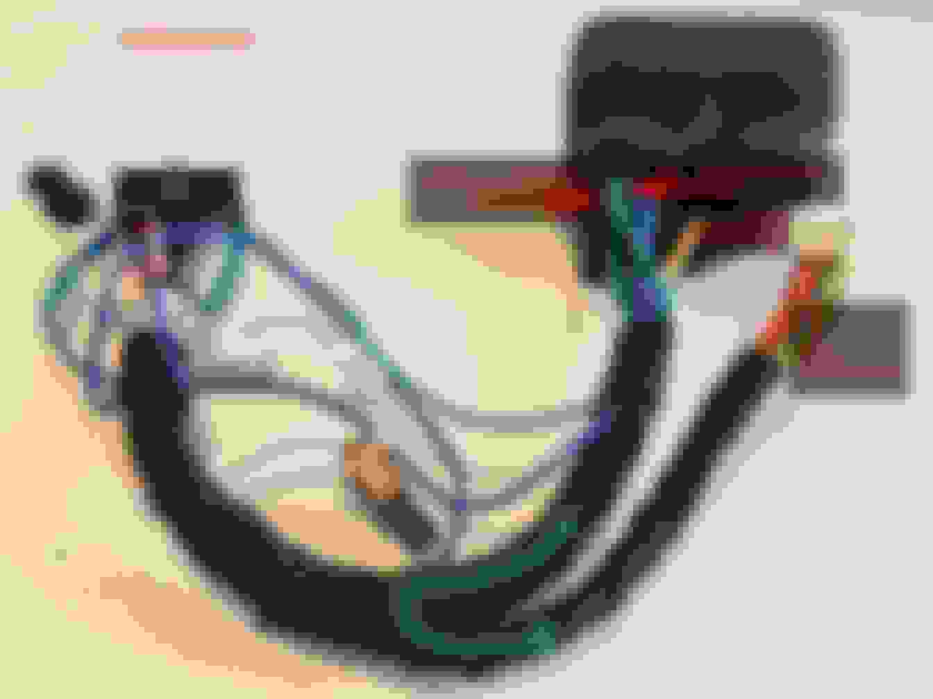
So I dismantled my trunk parts to test the wiring ... however I found power was being delivered to the harness ... so I looked back up front again.
I found this device that is a filter that is in-line with the yellow wire. I opened it up and found a 15A fast blow fuse. I purchased another fuse (using a slow blow as tester for now) and the unit powered on ... however, the connection appears to be intermittent somewhere. I need to find out where it is intermittent. I believe it may be the pins at the plug to the head unit or between the head unit and this filter .. I messed with it for so long that my battery went dead so now I need to charge it. My question now is how do you un-pin the connector? I can unpin many of the Mercedes connectors as they have locking tabs. But the connector to the head unit does not appear to have tabs that are easily visible or convenient to get to. Could you let me know how to unpin it? I think that may be the culprit after all ... the connector pin was probably loosely crimped causing intermittent connections and finally blew the fuse.
OK .. so I looked at this some more ... The filter appears to be the issue. When I twist it slightly, the head unit turns off. I can't seem to identify where exactly the issue is as when I open the box, the issue is gone. I want to get rid it ... I have looked at pics of other people's wiring and don't see this on theirs. I was planning on cutting it off and possibly adding an aftermarket in-line power line filter. Any thoughts from anyone on which one to use? It needs to support at least 15 Amps.

 09-20-2016, 01:04 PM