When you click on links to various merchants on this site and make a purchase, this can result in this site earning a commission. Affiliate programs and affiliations include, but are not limited to, the eBay Partner Network.
hello from Denmark i am so stuck Have a car with flashing right front light, fault in cluster with battery and SRS, radio and upper control flashing/goes out. Xentry have a lot og codes and Can erros. i have used: http: www.carlogic.org/bg/data/MB%20CAN(ICC).pdf last pages, to look at the network and i can get fault to stop with pulling one connector from Can B X30/4 Put in and all are flashing again.
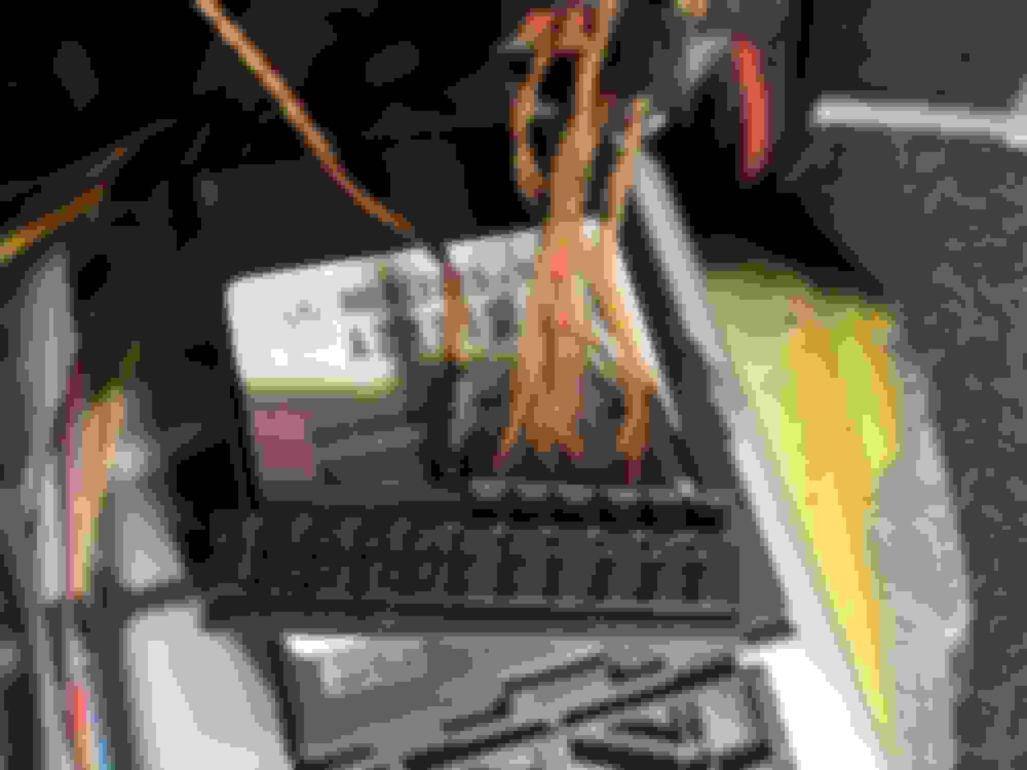
Follow the brown brown/red and can see it goes out unter paasenger right to engine room so cant follow longer messuring 40 ohms on connector pins. Cant find a wiring diagram on X30/4 Sry about my bad English
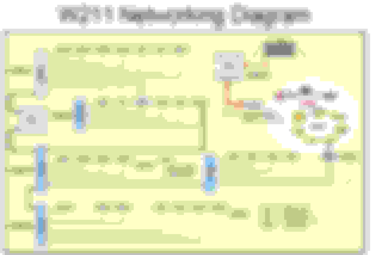
Junction X30/4 is under the passenger-side footwell. Diagram shows seven connections and the OP's photo shows either #1 or #7 unplugged. The diagram below shows eight connections so this will call for a view of the WIS to determine which connection is which according to the schematic.
From the diagram, not(!) any schematic, connections are:
-X30/7 junction block CAN B Driver's side rocker panel
-N10/11 Passenger-side SAM
-N69/2 right-front Door Control Module
-N69/4 right-rear Door Control Module
-N82 Battery Control Module
-N2/7 SRS
-N72/1 Upper Control Panel
-N32/2 ESA right-front Seat Adjustment with N32/22 right-front Dynamic Seat Control daisy-chained(?)
Need to know which connector is unplugged as I cannot see the numerical designations on the junction block; I am guessing they are on the other side. Once we have that, assuming the connectors are in their original locations in the junction block, should be easy enough to find the schematic and point @docaalfa in the correct direction.
Last edited by bbirdwell; 04-01-2024 at 11:12 AM.
Reason: Additional photo
dont think you can take the numbers from 1to 7 as the connector dont have numbers on, and in number 2 is the wire from X30/7 brown/black, but it can be the missing spot on diagram?
i cant find anything not working with the last fault can wire out. dont have memory seats.
Junction block position matters.
Post your VIN. I found the X30/4 connections by position for my car just to confirm they are in the schematics. I'll look them up for you and list them in a post.
The schematics I am looking show only Brown/Red and Brown two-wire connections on junction block X30/4. There is no black in the schematic for my vehicle.
For the W211 sedan, connection #2 on block X30/4 goes to N10/1 (driver side SAM) on right-hand drive cars (annotation U13) with M113 and M156 engines (annotation U137 and U152). On left-hand drive cars, connection #2 on block X30/4 goes to N10/11 (Passenger side SAM) according to annotation U12.
Again, post your VIN as multiple configurations were made.
Following is from document number pe00.19-p-2300-99da, wiring diagram CAN bus interior, Model 211 voltage distributor for cockpit CAN, X30/4, VIN WDB2112221B219765
-connector #2 to N10/11
-connector #9 to N32/2 as of 05/04 (May 2004)
-connector #3 to N93
-connector #4 to N72
-connector #5 to N69/4
-connector #6 to N69/2
-connector #7 to STH per annotation U579 (valid for stationary heater STH)
-connector #8 to N2/7 restraint systems control unit
-connector #11 to N82 battery control unit as of 05/06 (May 2006)
-connector #10 to Special vehicle multifunction control unit per annotations U520 (taxi) and U649 (government vehicles both export and domestic market)
-connector #1 to X30/7
Many thanks for your informative posts -- much about the WIS/ASRA wiring schematics has been suddenly illuminated.
Hello so many thanks for getting me some more info.
I have only treid very fast to seen up the numbers 1 to 7 is the same on x30/4 but only seen that x30/7 was on number 2 and not 1.
but when i get time again i will follow the number 7 as it is for extra heater and it is not working at the time. will take the wire out off the heater and try with connector 7 in again.
Again many thanks
S�ren
hello from Denmark i am so stuck Have a car with flashing right front light, fault in cluster with battery and SRS, radio and upper control flashing/goes out. Xentry have a lot og codes and Can erros. i have used: http: www.carlogic.org/bg/data/MB%20CAN(ICC).pdf last pages, to look at the network and i can get fault to stop with pulling one connector from Can B X30/4 Put in and all are flashing again.
Follow the brown brown/red and can see it goes out unter paasenger right to engine room so cant follow longer messuring 40 ohms on connector pins. Cant find a wiring diagram on X30/4 Sry about my bad English
Solved after getting last post on the X30/4 pin i could take out the stationry heater an the can bus was fault free.
Many thanks pointing me in the right way
Glad to be of assistance. FWIW, last Friday I had a failure of my W210 CANBUS that took out the driver's door control module (seat, mirror, window, steering wheel adjustment); everything else worked. Once again, it was a faulty rear door control module (I replaced the other side in June of 2023). This time, it only took me 20 minutes to identify the faulty module (right rear door control module) using a multimeter and the schematic while removing and replacing connectors one at a time. Going to order the right rear door control module today. I'll post another CANBUS diagnostic DIY in a few days.
Is the position really relevant?
They are just internal bridges.
can bus directs the information by ids, all units receive the same information.
I could be wrong, I just want a reasoning that I can understand so that in the future I can make decisions without information.
The connector position in the junction block matches the connector position numbers in the schematic. If the connectors get swapped, you'll be chasing ghosts because the schematic no longer matches the actual connectivity of the modules.
How did I learn this? I cleaned the connectors in the junction block on my W210 all at the same time (big mistake) several months before when the failure was intermittent. I got all into the proper position except for...number 2 and number 7.
#7 is driver side rear door window. #2 is Front SAM.
When both front DCMs (#6 and # 8) and the Lower Control Panel (#1) failed, I pulled connectors from #10 to #1 in the X30/7 junction block while comparing to the schematic and monitoring voltages. No change on #10, nor #9, nor #8. Pulled the connector from position #7 which I thought was the driver side rear door but was really the accidentally swapped in Front SAM; Lower Control Panel and both front DCMs were still inoperative so no change and the CANBUS still unstable...so I plugged the connector back into the junction block thinking the left rear door is not causing the failure. No change on #6, #5, #4, or #3; CANBUS still had incorrect voltages. When I got to position #2 and pulled the connector, the CANBUS stabilized with good voltages, both front DCMs and the Lower Control Panel came back online functioning normally. I'm thinking I have a bad SAM killing the internal CANBUS and might have to replace the SAM. Lower control panel was now working except it would not control the driver side rear window; that was when I started scratching my head and pulling my hair out. The rear window switch would but not the lower control panel (position #1). That was when the proverbial light bulb came on and by the process of elimination I identified the two swapped connectors. Moved the two back into the proper position and now my troubleshooting matched the schematic and everything made sense.
I spent maybe 4-6 hours trying to figure out the above and then 15-20 minutes to confirm once I realized the problem was one I caused myself.
That was June of last year. Two days ago I diagnosed a failed passenger side rear door control module (position #9) in less than 15 minutes because the connectors matched the schematic and I could go right to the suspect module. Took me more time to reglue the rear door panel than it did for me to identify the failed module.
You are 100% correct the junction block is just a bridge. If the wires in the harness themselves were labeled 1 through 10 with tags I would have no issue of plugging the connectors into the junction block randomly. But the wires are not labeled and that is where the fog of diagnosing takes over...
 04-01-2024, 10:07 AM