When you click on links to various merchants on this site and make a purchase, this can result in this site earning a commission. Affiliate programs and affiliations include, but are not limited to, the eBay Partner Network.
Luckily, the ECU kept the quantity valve closed at the end, so I could record the live fuel rail pressure decline on the real, which would show any leaking injectors. Pressure drops by 0.6 bar (9psi) every 10 seconds, so it seems the injectors are actually closed.
Here is the capture of this decline:
and here I am wondering what it is that I’m actually seeing here. Why would the quantity valve stay closed? It’s a normally open valve, closure triggered by cam position, closure is timed in milliseconds. What’s keeping the valve shut? Cannot cross-reference this to the scope data unfortunately, but I’ll try to capture this moment once more.
Post all the pico raw files please. zipped it before you post, otherwise MBforum wont accept pico file type.
This laptop of mine I travel with has pico6 and pico7 software and is my picoscope laptop.
I need to calculate something.
By the way, S-Prihadi, do you remember where you connected your signal and ground on the loom while measuring your posted graphs?
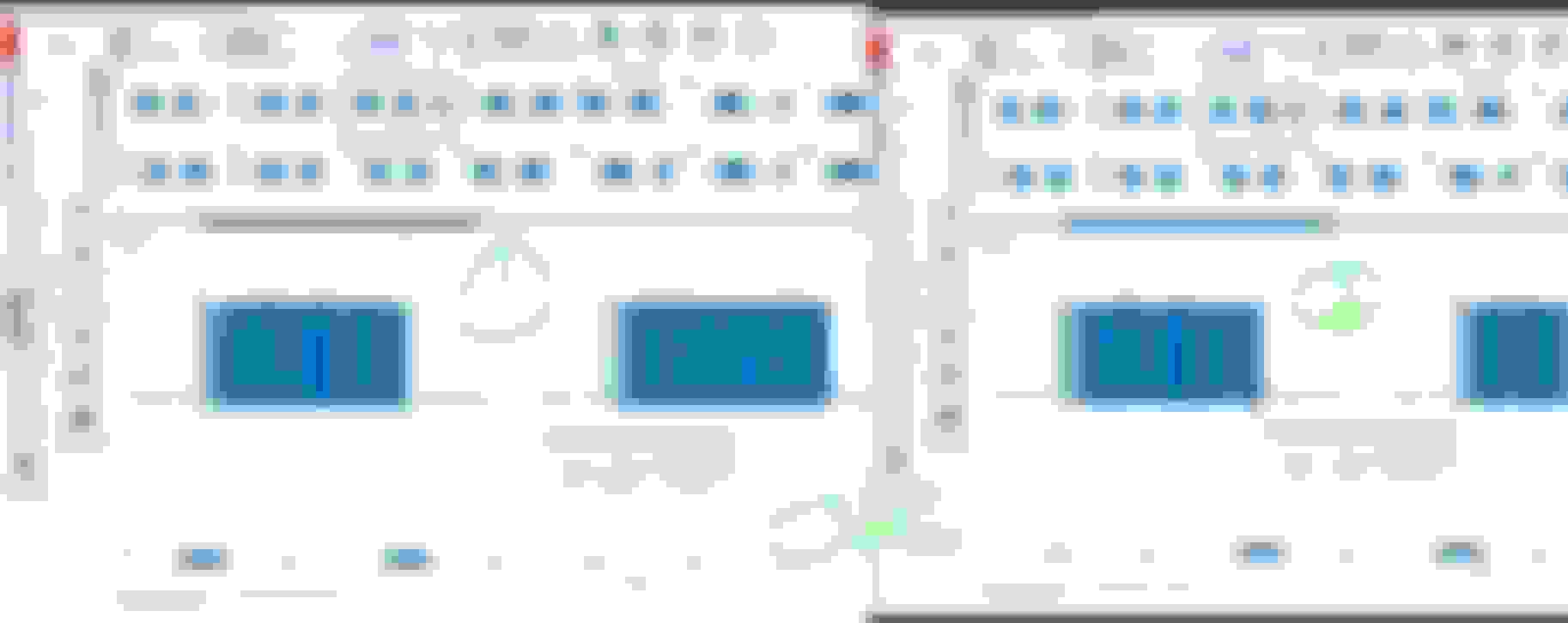
In the below example, you see a very distinct negative spike when the quantity valve falls back to open. This spike is expected, as the piston returning will create some current in the coil. However, I don't see these spikes on my scope. My ground is connected to the vehicle ground, maybe that creates a bit of a difference?
Yes, that is a very good catch on your part to see the reverse spike on my Y94, typical reverse spike of a coil when power is removed.
Now, we scope at Y94 itself, we can not scope at the driver side of the circuit inside the ECM.
Can that reverse spike is actually being used by ECM as a signal telling ECM, the actuation has stopped ?
Here is why I need your raw file.
The timing of your Y94 is very weird.... I mean the timing of Y94 actuation and de-actuation is not right. We can't yet say ECM is at fault, now that we know your Y94 does not generate the
reverse spike like my Y94.
Here is your Y94 actuation which seems decently normal, but what baffles me is, based on my calculation, your cranking speed is only like 60 CRANK RPM.
This is way too slow. My engine is 165 to 200 RPM CRANKspeed during crangking , depending on oil film left over when and if I do not touch my car for 30 days.
I like pre-lubing my car when I have not touch it for 30 days, I use the compression test feature of MB Xentry, which reads piston crank speed , sort of.
Our engine does not have CLEAR FLOOD MODE of typical US cars, which when brake pedal fully depressed and accelerator fully depressed, you can crank the engine and engine
on purpose WILL NOT START.
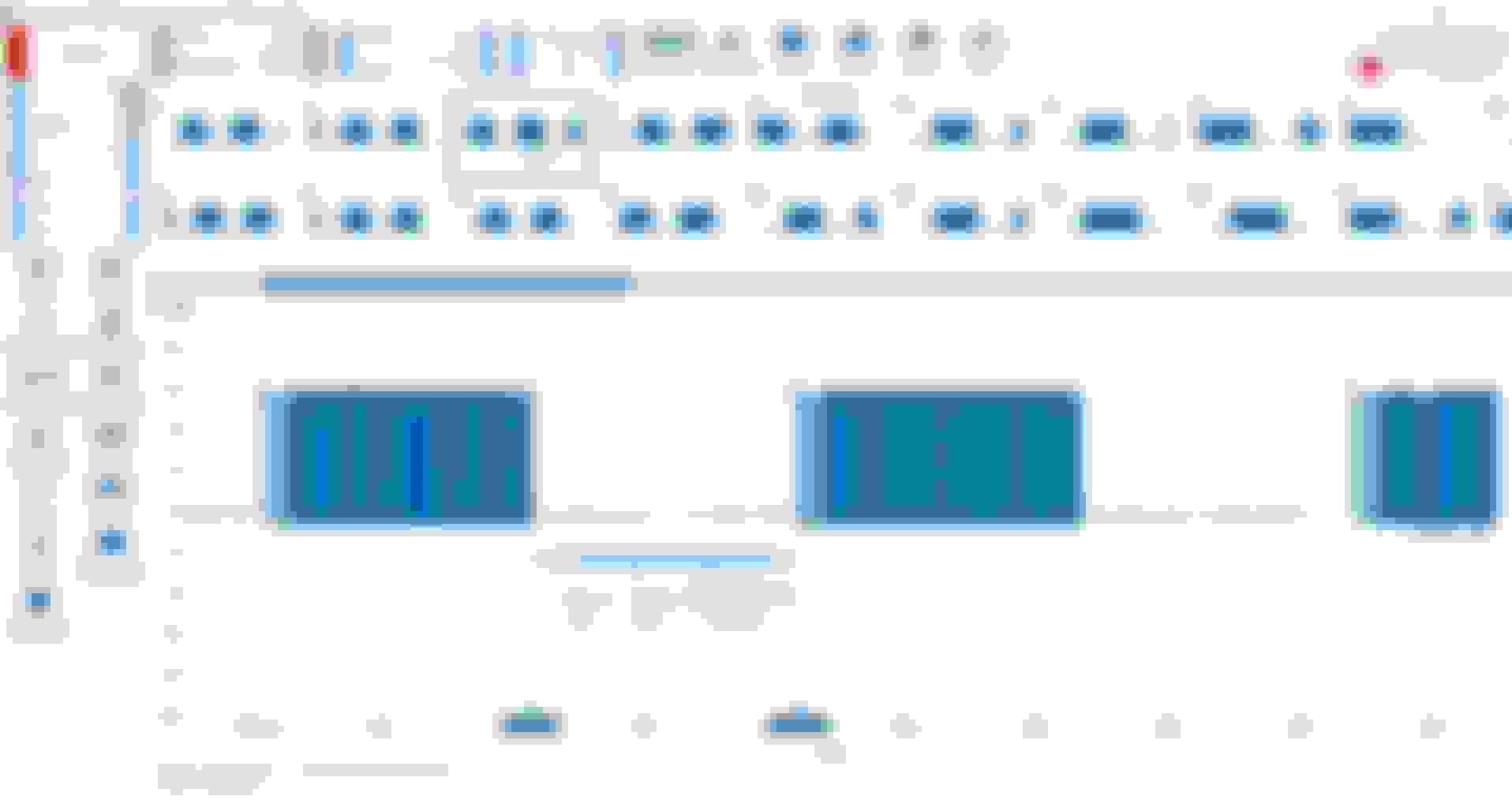
See that the Y94 duration of actuation which we assume as 60 degrees ( CAMshaft degrees ) as max for 2 above images.
The duration is 20.x milliseconds for the 1st PWM pulse and then the dormant period between 2 pulses of PWM is also 20.x millisecond.
I done reverse calculation to get your cranking speed, otherwise the duration of Y94 PWM signal on its own is not useful.
Since you did not catch crankshaft waveform, I can't do other method to know the actual crankshaft revolution speed, other than a reverse calculation based on the norm....of my engine crankking speed.
However the number dont add up.
If I use your Y94 20.x milliseconds actuation and rest period, the cranking speed CRANKshaft RPM is then 60 RPM only.
Try to verify my calculation, just in case I screwed up.
But why cranking speed is only 60 CRANK-RPM, no way you will not know if starter sound so lame-slow.
Now come the crazy one. I must assume that at scope capture page 59 below , your cranking speed is still the same as page 9 which I used to reverse calculate your CRANKshaft cranking RPM
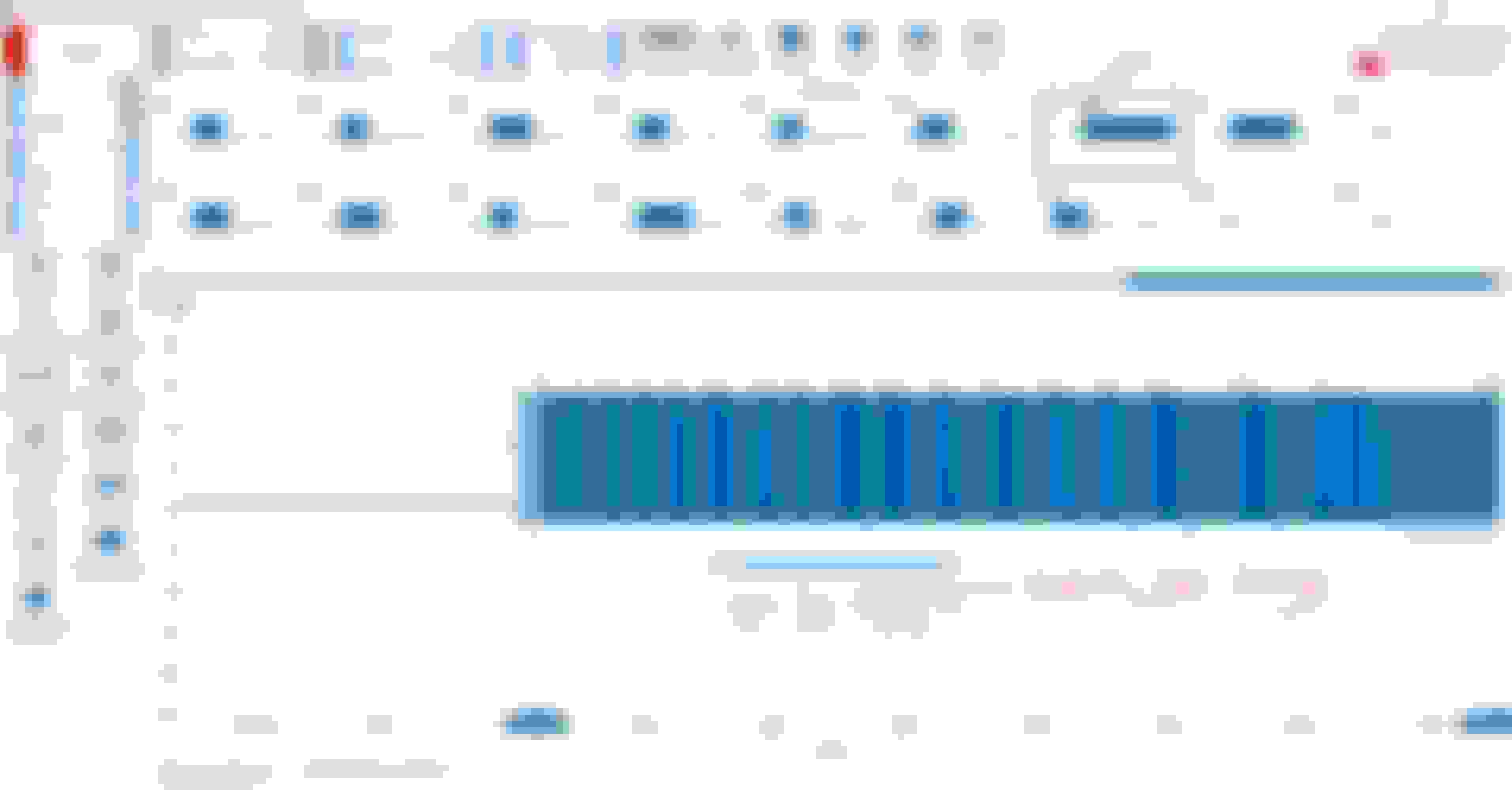
Above duration of Y94 actuation is totally bonkers, it does not make sense at all. Near 73 milliseconds of actuation is way too long.
I think this weird long 73 milliseconds is when your HPFP probably loose pressure rise.
Hhhmmm, I let you do more thinking, while me want to do more thinking too.
We shall discuss further later.
By the way, the Bosch HPFP pump of yours, it has only the Bosch P/N but no MB Part/Number yes ?
Can you go back to seller and top up a bit more money for MB version ?
Take 20ms as in the screenshot above. The time between the start of each pulse is double that, so 40ms. As there are 3 lobes on the camshaft driving the HPFP, that would make 3x40ms -> 120ms per camshaft rotation.
The crankshaft runs at double the speed of the camshaft, so it takes 60ms per crankshaft rotation.
60 millisecond per rotation would give 60*1000 milliseconds per 1000 rotations. So that would read 1000rpm in my book.
Testing things right now, I connected the scope probe at both pins of the solenoid instead of 1 pin on vehicle ground to inspect the specific 'spike' on solenoid release. It's there if I measure this way:
So the signals are at least similar, that' sone thing I'm learning here.
And another very weird thing I captures on video. I start the engine, idle is too rough so it dies by itself (@0:09), then the pressure rises all the way to 126 bar (1800 psi). After starting the engine with this high pressure still in the rail, it runs great for 3 seconds, until the pressure gets too low. You can see the quantity valve being controlled accordingly, as the pressure drops the duration of the closing of the valve increases.
It makes me rethink the low pressure side, is there actually enough fuel being delivered to the HPFP?
I have corrected the formula mistake at field marked in red In milliseconds, per 1 degree of CAM revolution , it was a wrong constant I use, a 60 as in seconds and
not 1,000 as in milliseconds per 1 second ...LOL, my apology.
Since we do not have crankshaft waveform which we can take CRANKshaft RPM from it and we are quite blind on actual CRANK or CAM RPM.
I suggest you hook up your scope to Ground and Signal of CRANKsensor which is a 3 pins, see the N3/10 ECM schematic and its there, but you got to back probe at the ECM big connectors,
as I doubt your hand can reach the CRANKshaft sensor at bell housing.
For others who may in the future look at this post for assistance, here is how the 60 degrees calculation comes about for a 3 fuel lobes camshaft which is a 120 degree per lobe.
So the first two scan captures are OK, them being 20.x milliseconds and at 1,000 crankshaft RPM.
The 3rd image capture is still something wrong. 73 milliseconds is will be worth approx 180+ CAMshaft degrees if at 1,000 RPM.
I think it will be best you also scope minimum the CAMshaft sensor, if not the CRANKshaft sensor or both if your Pico is a 2405A 4 channels.
Just in case there are signals anomally at either one of those 2 sensors, which still does not produce CAM-CRANK corellation code because your engine
did not run long enough to trigger such DTC, if any.
This 73 milliseconds of Y94 actuations assumed at 1,000 RPM idle , need to be solved first, this is not normal.
=====================================
Now with your scope ground direct at the Y94 ( but you got the 2 pins reversed probed or did you invert the capture ? ), you get the reverse spike voltage. OK, that is nice.
You now see true unfiltered signal of Y94.
Next time do not believe in what other people say about scope ground is to be ALWAYS at battery ground, as long as you do not get mixed up the grounds between other channels of the scope,
it is fine , even for common ground scope like Pico 2000 series. I have 2205A Pico and started with that, I love that little baby scope.
============
J wrote :
And another very weird thing I captures on video. I start the engine, idle is too rough so it dies by itself (@0:09), then the pressure rises all the way to 126 bar (1800 psi). After starting the engine with this high pressure still in the rail, it runs great for 3 seconds, until the pressure gets too low. You can see the quantity valve being controlled accordingly, as the pressure drops the duration of the closing of the valve increases.
It makes me rethink the low pressure side, is there actually enough fuel being delivered to the HPFP?
I can't comment on that, because you told me that you did the LP fuel flow test well and all is good, so I believed that.
I suggest you hook up your scope to Ground and Signal of CRANKsensor which is a 3 pins, see the N3/10 ECM schematic and its there, but you got to back probe at the ECM big connectors,
as I doubt your hand can reach the CRANKshaft sensor at bell housing.
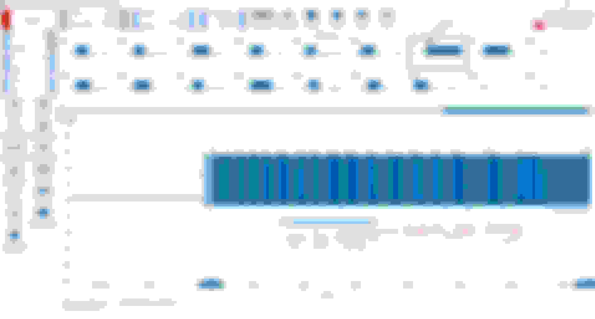
I did so this afternoon, I'll post an example here. Vertical lines are still 10ms I think. I'm reading the exhaust cam / right side from the ECU connector, I guess this is the right cam for the HPFP lobes.
The 3rd image capture is still something wrong. 73 milliseconds is will be worth approx 180+ CAMshaft degrees if at 1,000 RPM.
It's the last bit before the engine dies, it's probably already running below 300rpm. As the reference to engine speed is missing, it does indeed look very odd..
Now with your scope ground direct at the Y94 ( but you got the 2 pins reversed probed or did you invert the capture ? ), you get the reverse spike voltage. OK, that is nice.
You now see true unfiltered signal of Y94.
Yeah, the pins were reversed. I back-probed the actual solenoid connector which is well hidden, so I could not swap anything over, I just made use of a signal I could get. But the spike is there, that's the important bit.
I can't comment on that, because you told me that you did the LP fuel flow test well and all is good, so I believed that.
I know, and I did test it. But I get such weird readings, for example this one on the rail pressure:
The spike halfway is startup of the engine, the pressure drops, as usual, but the pump almost recovers. It cannot get the pressure to the desired 50 bar (725 psi), slowly looses pressure and then the engine stops. That's when the pressure starts rising again up till ~25 bar. It's such weird behaviour that I'll be testing the low pressure side once more, this time with someone in the car to start it up, while I can test flow during that exact moment.
Wait wait wait a minute..........
Are you saying the red channel is a CRANKshaft waveform ? It does not look like that....
The blue channel is a CAMshaft waveform.
Let me try to dig my old post, I believed I may have posted a CRANKSHAFT waveform.
It is a 58 teeth and 2 empty = total 60 pulses with the 2 being missing. Some call it 60 teeth less 2, some call it 58+2
Yeah, so the cam signal looks okay. It's not possible with this info to assess if the quantity valve timing is in the right spot, however, as it's position is linked to the cam timing, and constant in that respect, and at startup I build some pressure, the timing must be correct.
Another by the way, I tried scoping B4/25, the rail pressure sensor. This way, I could assess pressure deltas during the closing phase of the quantity valve. Unfortunately, it doesn't give any specific readings on pin 2 of the sensor, just a steady 4V signal.
Another by the way, I tried scoping B4/25, the rail pressure sensor. This way, I could assess pressure deltas during the closing phase of the quantity valve. Unfortunately, it doesn't give any specific readings on pin 2 of the sensor, just a steady 4V signal.
I never scoped that pin 2, yet. B4/25.
But pin 2 supposedly HP fuel pressure sensor and pin 3 is fuel temperature.
Commonly a 5V sensor would be a 0.5 to 4.5V range and the 4 volts window is then per X milivolt equal to Y Bar.
I do not know if that sensor is voltage up as pressure up, or the opposite.
I think if our engine is a 200 BAR rated GDI, the sensor would be a 300 BAR max.
============
BTW, these long pulse duration at pages I marked red is weird. If page 59 could be engine almost choking and 300RPM, but these middle pages ?
You better capture CRANKshaft sensor signal while scoping Y94, if you have not done so.
You have to eliminate any possibility that CRANK sensor has intermittent bad signal but not totally bad.
Hmm, thought the blue line was the crank. Very useful reference document, I really should get WIS to get to this info. I'll give the engine another prove, I must have connected to the wrong pin.
I performed another low pressure system just now. On the Schrader valve, I see a rapid pulsing between 60 and 70 psi, pulsing is probably the result of the HPFP pressing back into the low side. If I check flow during idling, fuel pressure on the low pressure sensor is still healthy (~70psi) while showing a proper fuel flow at the gauge I have. There's really not much else left than just the HPFP itself it seems, I'll get an original MB one, unmount the current one, while carefully checking the cam lobe and roller tappet for any issues.
This is the manual gauge measuring pressure during idling of the engine.
Hmm, thought the blue line was the crank. Very useful reference document, I really should get WIS to get to this info. I'll give the engine another prove, I must have connected to the wrong pin.
I performed another low pressure system just now. On the Schrader valve, I see a rapid pulsing between 60 and 70 psi, pulsing is probably the result of the HPFP pressing back into the low side. If I check flow during idling, fuel pressure on the low pressure sensor is still healthy (~70psi) while showing a proper fuel flow at the gauge I have. There's really not much else left than just the HPFP itself it seems, I'll get an original MB one, unmount the current one, while carefully checking the cam lobe and roller tappet for any issues.
This is the manual gauge measuring pressure during idling of the engine.
Yes that is a clean fuel filter you have at that kind of pressure at the test port with fuel flowing out of tester tool. NICE....
If indeed a Bosch genuine MB HPFP is the solution, I am curious what is the difference MB special ordered/requested for the HPFP from Bosch ?
I know for oxygen sensors wide band and narrow band one, Bosch one if correct part number is plug and play.
My front wide band on my engine is by Bosch the rear ones narrow band is by NTK.
I replaced them all to Bosch, from FCP Euro reccommended Bosch P/N and its good, no issue.
There are known proven difference if on a car tryre.
BMW has special version of Mich Pilot Sport 4S, which is BMW version and the compound is different, no bull-shiet. The label is BMW too.
Mercedes has many special order Hirshmann and Kostal electrical connector which is only sold to MB, but we can see the difference, which are the groove or channel, or called coding by them Germans.
We can not buy these connectors if not from Mercedes dealers.
I'll have a close look on part numbers. There is a slight difference between the original pump on the car (0261520218) and the replacement Bosch item (0261520217). However, on FCP euro, the Bosch number is also 0261520217, and looking across different websites they all mention 0261520218 and 0261520217 as similar.
For sure there are specific tyre versions for different manufacturers, and it is indeed labeled on the tyre wall. For my Lotus, there were specific 'LTS' compounds of various tyres. Main difference was sidewall stiffness. The LTS tyres optimised this for the relative low weight of the car (only 160kg static load on a front tyre for example...).
U know J, if say ur crankshaft sensor is intermittent bad or even dead, your engine can still start but limp mode.
So scoping its waveform to see if it is actually good , is a must before next step of action.
Something I still wanting to verify soon is :
The said timing document above from MB, at what RPM and engine coolant temperature is that ?
or
Do I need to un-plug the exhaust valve oil solenoid , so that VVT of exhaust system stay fix and not do its variable action ?
See at the bottom for VVT actuation data, that is my worry. It is dynamic aka moving if from COLD start for exhaust VVT sprocket.
Hmm, interesting. I would think that the diagram in the PDF is used as a reference only until engine startup has begun. Its purpose would be to provide multiple means to derive crankshaft position / TDC. As soon as the position of the crankshaft has been determined (still during cranking), timing of injection and ignition can be decided and startup will engage. In the YouTube video at 0:02, you can see that engine speed is shown (125 1/m), before the camshaft positions start to change.
The ECU strategy might be to only allow the VVT system to work if the ECU can derive engine position from the crankshaft hall sensor. If that sensor fails, the VVT system might stay disabled so the ECU still gets a known good engine position.
Mercedes SLR McLaren 722 S Is Extremely Rare Example Modified by McLaren
Slideshow: A one-of-one U.S.-spec Mercedes-Benz SLR McLaren Roadster became even rarer after a factory-backed transformation at McLaren's headquarters.




























 or did you invert the capture ? ), you get the reverse spike voltage. OK, that is nice.