SUBFRAME OTHER 2 BUSHINGS
Bushing item 50 is A204 351 04 42 Axle housing to rear subrame. This hold the differential casing..
Bushing item 40 is A204 352 10 65 Rubber Bushing. Spring control arm to subframe
The diameter of these two bushings , I can not get the data.
===========================
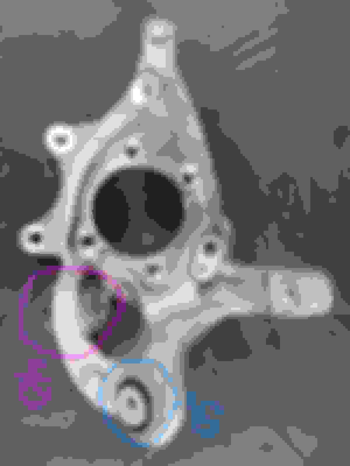
Rear Wheel Knuckle bushings
Bushing #50 for rear wheel knuckle serves this ARM item 540.
Item 540 ARM has a few names : Pushing Arm or Rod or Thrust Arm
The diameter of these rear knuckle bushings , I ALSO can not get the data.
so I have to buy these bushings first and find the bushing tools which will fit.
For now, I recently got this low cost bushing tool only.
The construction steel is good, I am surprised. In Amazon USA it will be this one :
Supposedly these are the sizes, but I have not use my caliper to measure the accuracy yet. Should be within 0.5mm tolerance I guess. In millimeters, each of its ID and OD.
=============
If you guys wondering why would I need to replace all these bushings before they are visually torn ?
Torn or noisy is too late already.
I like brand new feel of a tight car and since target to keep is 20 years old, the 10th Bday is the middle age refurbishment program, mechanical side.
These 3 bushings : SUBFRAME - Bushing item 40 is A204 352 10 65 Rubber Bushing. Spring control arm to subframe
Bushing 50 and 40 of rear wheel knuckle
They control the dynamic alignment of the rear wheel. Aside from 4 other arms of the total 5 arms rear suspension.
If I want my rear tires to wear as beautiful as I am getting now, I need to give love to these 3 bushings.
The subframe main bushings, those 4 unique shaped ones and the DIFF bushings 2 of them + DIFF mounting, is what made a car as vibration free as MB intended design.
Vibration from misalignment between tranny output to differential input is what I meant, not only from road surfaces typical vibration.
When I get those bushings in hand, some would be a 3 months wait possibly, I will share the sizes, so you guys can hunt your own bushing tool kit.
PS
While doing these bushings, the rear CAMBER ARM LEFT and RIGHT need to be replaced too , albeit still withing static alignment value, that arm has a tough working life during
ride on bad roads and when cornering hard.
A205 350 61 03 Camber Arm ( rear ), LEFT. 1pc
A205 350 62 03 Camber Arm ( rear ), RIGHT. 1pc
I would like to add that there are 2 sizes for item 20 , FRONT subframe bushing. It will depend on your chassis number.
Mine per my VIN is using the 76mm OD one and not the 85mm OD one.
The subframe also has 2 versions, one for 76mm and one for 85mm bushings.
However, the suggested latest model subframe P/N would be the 85mm bushing type.
Thus if you guys get new subframe for corossion warranty, which the bushings are already included, I think it will be a 85mm one if stock is fresh and not before 2013.
So next time using VIN to buy the bushings, you got to know the new subframe P/N you got during warranty aside from using your car VIN.
These are the local prices I am getting, after 10% VAT/sales tax.
Not bad actually, more so for Camber Arms. These mark up is not as high as some components I been buying.
Should arrive at worst by Dec 2023.
Seeing OEM W212 Models have no front �Camber� or �Caster� adjustment and no rear Camber to resolve costly, premature excess edge tire wear - only basic Toe �directional� adjustment !
Not only do we manufacture Front and Rear adjuster kits to resolve this situation (providing precise �single wrench� adjustment� of tire contact angles, essential - allowing to spread load more evenly).
WE ALSO MANUFACTURE UPRATED PERFORMANCE BUSHES FOR THE ENTIRE FRONT AND REAR SUSPENSIONS.
SEE SPOILER
AUDI to VOLVO � K-MAC Experience Of Resolving OEM Suspension Shortcomings Since 1964 !
Spoiler
#503028Q $890 �4� REAR SUBFRAME BUSHES. Kit also includes �Bush Extraction Tools� so no other special tools required and designed to allow fitment without need for subframe removal !!
#503228J$380 Replaces the �2� Diff bushes - K-MAC are MONO BALL / SELF ALIGNING.
#502628K$480 Replaces the �6� REAR MULTI LINK ARM BUSHES also with bush extraction and insertion tubes.
#502916K$480 (4MATIC #503616K) Replaces the 4 FRONT HIGHEST WEARING BUSHES and same time providing for the FIRST TIME CAMBER AND CASTER ADJUSTMENT. Includes bush extraction tools (Camber can be fitted without need for arm removal).
#502126K$480 Rear lower arm inner bushes FOR CAMBER ADJUSTMENT ALSO FOR FIRST TIME and also doubles the existing rear Toe adjustment to compensate for new Camber facility. Bush extraction tools provided allow fitment without need for arm removal.
NOTE: These K-MAC UNIQUE Patented design kits allow �ultimate adjustment� - direct on Alignment rack (under load) !
DHL Express delivery Worldwide $40 one kit, $20 each extra.
Since you are hitchhiking on my post ( I endorse all genuine MB components and not aftermarket ) , you might as well provide complete information for other members.
01. Tell us, what diameter is your front subframe bushing, now that we know there is a 76mm and an 85mm version
So your inner sleeve is removable..... therefore it can surely spin ( with friction probably ) inside the elastomer/rubber because it is not bonded.
Those small river/vein like machining cut on the inner sleeve OD, are those for lubricant trapping ?
How then your bushing absorb these forces :
Fully bonded Rubber - Metal bushes
These fully bondedantivibration rubber bushes are a type of anti vibration bush that consists of two cylindrical metal tubes which are bonded with rubber in the middle. These rubber metal fully bonded bushes consist of 2 concentric metal sleeves with rubber securely bonded to both of them. The bush is designed to accommodate small torsion, conical and axial movements and can endure radial loads.
The Rubber Metal fully bonded antivibration bushes are used for suspension and can be pressed into a housing, which will provide absorbtion of vibrations in any directon - radial, axial, torsional and conical directions. The fully bonded bushes allow elimination of high frequencies through the elastic deflection of the rubber under the effect of the external couples which act on the metalic tubes.
Rubber is pre-stressed to provide the best longevity and dynamic strength. All movements are absorbed by bonded rubber. Sleeves have excellent sound and vibration isolation capacity.
Hi Certainly did not realize you were endorsing �strictly only all genuine MB Components� - do apologise therefore for our input !
We had presumed you and forum members would like to be aware that there was a cheaper alternative for removing / installing replacement suspension bushings (without the expensive purchase of complete tool sets) and the added advantage of not needing to remove subframe.
Also that �UPRATED PERFORMANCE BUSHINGS� were available - Replacing the OEM soft rubber air voided bushings (for those wanting tauter more precise steering response) - Less twitch, flex, loss of traction - whether street or for track days.
The other information we pointed out is - �seeing todays models� have only BASIC FRONT AND REAR TOE - WHICH IS �DIRECTIONAL� ADJUSTMENT. No longer Camber (or Caster) essential to adjust tire contact angles to resolve costly, premature tire replacement. (All brought about by the ever increasing speed of new car assembly lines).
WE HAD INCORPORATED THEREFORE INTO OUR REPLACEMENT BUSHES - Front �Camber� and �Caster� along with rear �Camber� and extra Toe (to compensate for the new rear Camber facility).
ABOVE PROUDLY WAS A UNIQUE K-MAC DESIGN BREAKTHROUGH - Revolutionizing how adjustment is made - We invented / patented the concept of bush adjustment - Ultimate (easily accessible �single wrench�). Fast, accurate, precise adjustment, direct on alignment rack (under load) !
REGARDING THE �4� REAR SUBFRAME BUSHINGS - manufacture both 76mm (which covers W204, C207, C218 & majority W212) or late model W212 front in 85mm simply mention when ordering.
RE BUSHINGS VERSUS OEM - AS EMPHASIZED WE MANUFACTURE �UPRATED PERFORMANCE BUSHINGS�.
WHICH ARE ENTIRELY DIFFERENT �CONCEPT / DESIGN� THEN OEM SOFT RUBBER BUSHINGS see website �ABOUT US�. As pointed out we have the experience of resolving OEM suspension shortcomings and manufacturing �performance� bushings longer then anyone else 59 years (1964) !
The bushings + camber arms arrived.
So I can take measurement for you guys later to buy the bushing tool...NOT from Mercedes
Start with the rear knuckle/spindle/wheel carrier if per MB EPC
26 pcs VEVOR bushing kit contains 20 pipes, which can be push pipe or receiver pipe. For their sizes, go to earlier post page.
.
.
All I need later is to make a small push disc of 46mm OD, or use Vevor one if working space allows.
The push pipe I use is aluminum and not steel. I can't find OD 40mm steel, but have ordered 38mm galavanized pipe for just in case.
So I thin down the alu pipe using dremel for the inside diameter and using angle grinder with fiberglass sort of polish disc for the OD, but hand sanding required to make it rounder ...LOL.
Bushings at the rear Subframe, but not the 4 main big ones. The 2 smaller ones.
The tool to use is a combo tools, the Vevor and the special subframe main 4 bushing tools UNT-M4334. Vevor pipe size stop at OD82mm/ID72mm as biggest.
So the push pipe is using Vevor, the receiver "pipe" using UNT-M4334. Remember, when the pipe becomes the receiver, its ID is what we need, not the OD.
I did not measure the 2 types of main subframe bushings totaling 4 pcs, as I have special dedicated tool for it.
I will share some information.
Both are from Lemforder, ZF group.
Shown below the bigger size one, item 30
These item #30 bushings have orientation, so observe the arrow and notch properly when removing the old one, to allow the new one to be positioned the same.
ITEM #30 - ABOVE when seen from below the car, so that face is the facing down face.
This is how it will be installed, that metal thingy heading up to car body. My caliper too "small" ...LOL
The top part of #30 also has orientation arrows, 2 in fact.
.
The bigger main bushing item 30 is 793 grams.
The rubber is NR / SBR
Natural Rubber and Styrene-butadiene or styrene-butadiene rubber (SBR) describe families of synthetic rubbers derived from styrene and butadiene
@S-Prihadi A truly amazing project! Did you figure out the mystery logo on A204 351 04 42?
btw another name for the "supporting joint" is "cross-axis joint". This is the component with two boots and 4 retaining rings. They are used widely in rear suspensions for premium and luxury cars from the late 1990s into the first decade of the 2000s.
Nope, can't figure out yet the unique logo.
The Camber Arm of the rear also is having that logo.
I won't be surprised if I can remove any other arms and photo up close all of the rubber part of the bushings, that same unnique logo will be there.
So who/what is the Mystery brand MB is using for their suspension arms ?
Why the stand alone bushings at rear knuckle/splindle/wheel carrier and others at the rear subframe ( except the 4 main ones ) are not made by Lemfoder ?
Even the front sway bar link is Japanese made by THK.
There were a number of rubber-component companies that were in the industry in the 1980s and 1990s, who either went out of business or who were scooped up by ZF in the 2000s. ZF in the past 15 years has been on quite an acquisition path. TRW was a big one, and they have acquired many other companies.
The mystery logo is probably from (I guess) a German, or European, rubber component company that is no longer in business.
I am going to Bali by week 2 December 2023 and be back by week 2 Jan 2024.
The car will be doing 2,000 miles approx return trip.
I might as well do the spindle/knuckle/wheel carrier bushings 2 types ( 2 + 2 ) and the spring control arm bushings 1+ 1 ( at subframe ) and the camber arm replacement next week, as 1st stage job.
The reason is, I do not do Bali-Jakarta-Bali run every year, so this is a good time I can split the main subframe bushings (4) and the DIFF bushings (2) as a separate task for mid 2024 as second
stage job.
This way I have the time and distance to feel 3 new bushings + camber arm* ( *has bushing too ) as stage 1 and 3 types of other bushing on subframe as stage 2.
Hoping I can feel how much improvement stage 1 and stage 2 separately would bring, instead of doing them both at the same time.
Also my rear Camber Arm value is what made me bought new arms. It is still within limits but its close to end of limit.
I got all 4 new tires about 500KM ago, 11 Sept 2023. I have not done alignment yet with them yet.
Currently rear Camber Left to Right is 24 minutes ( 0.42 degrees ) difference, where maximum is 30 minutes ( 0.5 degrees ) difference.
So it is very close to its end of useful life.
Good healthy camber keeps my tire wearing out pattern so nice and almost very equal inner to outer.
I also think that doing these 3 of stage 1 bushings is better when the subframe still to be on the car and not on my wooden cradle.
Just in case a high torque task required for the work , I do not want to shift and then drop my subframe on the floor if it were on my wooden cradle hahahahha.
I shall make a new post for stage 1 job next week. Keep you entertained
A wooden cradle, in the perfect scenario, would be secured to the floor or other solid structure. And the subframe would be secured to the wood cradle. This would allow any high torque work on the subframe to be done safely.
.
Yes, I got 2 lashing strap ratchet type already, to secure the subframe to wooden cradle .
I look at the rear wheel drive shaft collar nut WIS, size 32, that is the highest torque I seen so far on my W212 at 350Nm tightening, no extra degrees.
.
I recalled front caster and camber arm at 100Nm and 180 degrees. The 180 degrees sequence I did try to "measure" roughly and its like 250Nm or more.
Working height of 50cm of Quick Jack to do that kind of torque, I had to play Kung-Fu and my face turned green from exertion ...
The subframe weight I estimated with the DIFF on it would probably not exceed 120kg/264 lbs.
If I tighten to 350Nm ( 258 lbs ) and subframe not on the car.... the outcome may invite Uncle Murphy.
I actually already bought a bigger new torque wrench like 2 years ago a 406Nm ( 300 ft-lb) one, just for this rear wheel size 32 collar nut, as my biggest torque wrench at that time was 250Nm only.
I saw the local rep of the brand can't sell the wrench because it was imperial/foot-lbs in my metric country, so they sell cheap. The last unit. It should be US$500 ish.
This model : https://handtools-from-germany.com/e...-730na-40.html
I think I paid like US$175 max, but need the extra head attachments as extra, another US$150 more.
Removing and assembling the hub nut (collar nut) will be a challenge if you don't have a torque reaction to hold the hub/rotor. When the vehicle is on its tires, the weight of the vehicle and tire friction help for this job.
Impact tool for removal would probably not require a torque reaction. Assembling the 350Nm nut will require a torque reaction because impact tools should not be used for this step.
@S-Prihadi A truly amazing project! Did you figure out the mystery logo on A204 351 04 42?
btw another name for the "supporting joint" is "cross-axis joint". This is the component with two boots and 4 retaining rings. They are used widely in rear suspensions for premium and luxury cars from the late 1990s into the first decade of the 2000s.
What a unique bushing this one is ........... its like a ball joint/tie rod end in its articulation.
Item 40.
.
.
Mine is already kinda weak, loose no...simply not as tight as new one. Photo above is the new one. Now at 39,000KM / 24,200 miles.
This reminded me of the L shaped ball joint at front suspension arms I replaced at 25,0000 KM or so. Same thing, weak already due to abuse at the track, I can spin it easy with my fingers.
No noise, just weak and that L shaped ball joint I believe is responsible for the straight line steering performance at high speed, which I love so much about my car.
This one : RWD car only, 4-matic does not use this type.
============================
TIPS
01. FOR RIGHT SIDE, REAR SUSPENSION ARMS. I have not worked on the left side yet, but would be the same I am sure.....
The first arm to be have its bolt removed from wheel carrier/knuckle/spindle, best to be item 350, Strut Rod. The most angled arm by installation.
RIGHT SIDE VIEW - Strut Rod , item 350 is red arrow.
.
I made a mistake by removing spring arm first because I am afraid of the spring energy, and that made the wheel carrier/knuckle/spindle goes up by 3 inch / 7.5cm or so, as such the sway bar is blocking my tool.
.
See.......... it was better with spring arm still attached.
I am always worried of spring, due to its massive energy. Hence I undo the spring arm first
As safety measure, I locked the spring with a spring compressor, but as "DONT-KICK-MY-FACE preventive only and not to actually compress the spring.
The first arm I removed was Caster Arm, as I want to replace it. See, it is removed already in above photo.
Are you disassembling the complete suspension? All pieces are being disassembled?
A bit late now, but I would have first removed the spring, or followed the suspension disassembly steps so that the spring can be removed early in the procedure. This takes the stored energy out of the system as you have referred to. No need to be worried if the spring is removed.
To do the two bushings on the wheel carrier/knuckle/spindle , yes....suspension tear down is needed .
Quick Jack + 2 extra jacks as back up. One at DIFF and one at Front subframe. I worry of earthquake
.
My DIY bushing #40 push pipe works well.
Very tight space, push pipe need to be super short.
.
These scoring on my DIY push pipe for bushing #40 is the "un-roundness" of it , it is hand grind-ded down to 39.80mm from 40.00mm and I can't be super accurate doing so.
.
Installation of bushing #40 ruined my DIY push pipe , aluminum is too soft and I made it too thin. So I made a new one.
During bushing removal, the cavity for the bushing itself help my ALU push pipe to maintain its shape, but for pushing in a new bushing there is no cavity to assist by DIY push pipe.
This is bushing cavity helping my DIY push pipe to not expand.
My 1st DIY push pipe for bushing #40 before its demise
.
DIY push pipe for bushing #40 damage, the old one. I made a new one 1mm thicker.
This is how I damaged my ALU DIY push pipe for bushing #40 and also spread open the DIY U shape beam, which is the "receiver"pipe. This stupid beam is so weak, I think it is iron and not steel.
.
Solution. Cut Vevor ID40.80mm OD50.00mm pipe short, make it as receiver pipe. Use existing Vevor pipe with ID 38mm as INSTALL push pipe.
When a push pipe gets bushing REMOVAL duty, its OD must be 0.2mm smaller than bushing OD.
When a push pipe gets bushing INSTALL duty, its OD is not important as it will never need to be inside the bushing cavity at the wheel carrier.
Good thing the VEVOR ID40.00mm is not a true 40mm, but 40.80mm, otherwise I can't use it as receiver pipe for bushing #40 which is 40.01mm
.
Okey....back to work. Will update again the challenges tonite.
Now we go to subframe.
Bushing for the spring control arm, # 40
Have to remove 1/2 of my exhaust system. I done the exhaust solo. So I bought a 3rd motorbike jack.
.
My subframe craddle system, where I made the wheel base for the motorbike jack ... the wheel works very well, albeit 1/2 of exhaust system is not as heavy as a complete rear subframe.
The subframe craddle system making is here : https://mbworld.org/forums/e-class-w...em-cradle.html
One thing I realized about the 1/2 exhaust system because I remove it solo.
The cavity of the exhaust system under the bumper is bigger at the top part....because that is the shape of the 2 fat final mufflers
So when we lower the fat mufflers x 2, the bumper will hit the mufflers and won't let mufflers be lowered .
That is why I need to use the cargo strap to squeeze mufflers inward.
The squeeze distance is like 7cm or 3 inches.
The green is how wide the spread is originally. The red is how much I need to "narrow" the 2 mufflers together.
.
Without 1/2 exhaust removal, there is no space for bushing tool to work.
This is the longest metal bushing body of all and OD is quite big too , that means lots of friction to overcome.
I damaged 2 of the long threaded shaft ( spindle ) of the Vevor bushing tool set. The M10 and M12 size.
Not a regular bolt thread Vevor is using, they call them M10 and M12 , but that is the threaded rod OD and no information on the thread type.
Good thing I keep spare 1 meter of standard M10 threaded rod grade 8.8 steel.
The M12 of Vevor got damaged because one of the pipe from Vevor I need to cut shorter for the other two bushings on wheel carrier.
So the cut are 1/3 and 2/3 length. I use the 2/3 length for this long bushing, but since I cut using this simple machine :
the cut on a 5mm thick Vevor steel pipe is not a true square, there is "misalignment" of 0.5mm or so.
Thus when I use a round pipe surface not a true flat/square, the pressure to the bushings is not good full complete contact and that made the M12 threaded shaft got bent a bit
and also the bushing ( good thing the old one ) got a minor cut, see below :
.
After I damaged the Vevor M12 threaded rod, I then use the Vevor M10. The bushing ID is M12 maximum, so I can't use the bigger M14 and M16 from Vevor.
Almost 80%of bushing managed to be pushed-in, the M10 threaded rod ....its NUT ( the one with the bearing ) its female thread got damaged....DUGHHH !!!!!!
Since Vevor use a unique threaded rod, its nut is also matching to it and I can't use the M10 rod of Vevor with regular M10 NUT.
So I use my own M10 threaded rod and its nut.
To prevent paint damage on my subframe, I made from 1mm thick P.U sheet a protection layer.
This is how the bushing cavity is like. Seems they shaped a metal sheet to be a "pipe"
Installation of new bushing #40 of subframe.
Will continue tomorrow.
Bushing is not the only "fun" part of the job..................
ACME threads or I guess trapezoidal threads now a days but we always called them ACME threads. If it was good steel those threads would have been perfect for that application. Unfortunately chinesium steel is garbage and they stripped out.
Have not scene that cut and wrapped flat steel for a pipe application in a while. Its a cheap alternative to a proper pipe material. In this application its probably a ok.
Well, the Vevor tool is so cheap hahaha, can't expect much.
At least I get their push/receiver pipes in various diameters and their push/receiver pipe base is nice, it has groove to "zero" the pipes.
.
The 32mm collar nut for drive shaft and the 350Nm tightening torque.
The dry micro encapsulated thread locker. This type of sealant we work immediately tightening it when installed, the drive shaft' male thread will cut open the dry sealant and probably inside is "wet" and activation starts.
I have to tear down the parking brake to do this bushing job.
I hate parking brake so much !!!! It is so primitive and the spring is a pain to work with, the movement accuracy is so bad on drum style brake which the parking brake is one.
Its a fine balance between parking brake pad "touching" the drum while not activated and we need to do 7 click to lock it properly.
I need to remind others, make sure your tranny is in neutral or else you may damage your parking pawl when doing this 350Nm.
Get someone to apply the car brake too.
My parking brake adjustment with already : parking brake pad slightly "touching" the drum while not activated, and maximum 8 click..... can not survive 350Nm, the disc will spin.
So car brake must assist. To think of it, M276 3.5NA has only 375Nm at 3,000 RPM, I was doing by hand 350Nm at 1 RPM....LOL
The position of the wheel hub is a bit inside the wheel well, so I have to use a 4" extension on my torque wrench, or else the torque wrench will hit the rear door.
The 32mm nut MB uses is a low profile nut, unlike ordinary 32mm bolt which is taller and hence more grip for 32mm socket to work on.
I yesterday have not got a 3/4"drive extension bar yet, it was a 1/2" one I been using. This morning I got a 3/4" drive extension for LEFT REAR suspension work.
Yesterday and since I worked on the RIGHT REAR suspension, I been using Item 1 and 6 for impact driver to loosen the 32mm MB collar nut, no issue.
When I have to do the 350Nm torque wrench, I use the item 5 which is a 1/2 extension which I already damaged the detent ball, its gone, hence I bought a new one this morning item 7.
My 400Nm torque wrench as you can see, the head is change-able.
Yesterday right rear 32mm collar nut was tightened using item 1, 4, 5 and 6 a 1/2" system.... not nice. I best need a 3rd person to push on the socket tight to collar nut, 2nd person was pressing the car brake.
But I tried my best with my knee pushing in the socket tight ( my knee th 3rd person ...LOL ) to the nut and my arms ( short arm ) on the end of the torque wrench
...damn it ....350Nm is a bi-etch, since my position is so bad having my knee pushing in the socket tight to the nut.
I can't use my body weight and arm muscle to its full capacity due to the risk of the socket coming off the so shallow 32mm collar nut of MB.
I made a mistake, bought a 1/2" drive 32mm impact socket, I failed to see it is a 6 points and not the 12 points I required....it is short I like it, but useless for my MB
The shiny taller 32mm regular socket but 3/4" drive works OK though.
The Dremel , cutting the 32mm collar nut to make the folding "lock". I got my home staff to do it....LOL.
I cant do too well on tight small space and small object.
I do not want to fold the steel lip too much, Now it is good enough to stop the nut from ever moving more than 1mm...if it ever can move to begin with
The smallest cutting wheel is 18mm, and that is already big for the limited space and "sunken" work space.
.
==========================
The need to tighten all the bolts of suspension arms at RIDE HEIGHT is the time wasting process, but a must do.
Rear suspension has both bushing end arms, unlike front suspension arm which only have 1 bushing end.
So the rear suspension arms amount of work is so much more, when and if you want the proper way of doing bushing pre-load for best life and performance.
If only MB uses external torque bolt, I would suffer much less.
Why the heck MB chosen internal Torx is beyond me ?????.... takes more tool length to work with and also internal torx is weaker.
Camber Arm replacement is a pain-in-the-AZZ. Space wise it is a nightmare to torque it to 50NM and 90 degrees. 50Nm is not an issue, the 90 degrees is the issue
with only like 20 degrees torque wrench movement possible. Go up, I hit the sway bar. Go down I hit the other suspension arm.
LEFT REAR wheel carrier removed.
I now can do faster as I know the sequence.
First to be loosen and then unbolted at the wheel carrier. CAMBER ARM. #1 in red, item 250
In the WIS, names of the suspension arm sometime is different vs EPC. Here are their other names.
First one to be unbolted. CAMBER ARM. #1 in red, item 250.
No 4 in red, item 540. Pushing Strut or Thrust Arm is second one to be unbolted but place something in the bolt hole to make it stay, as that arm wants to go up because its setting is RIDE HEIGHT/Pre-Load.
I adjust a bit of spring control arm height, so it is not full droop. The reason being, since all the suspension arms bushing ends at the subframe are actually tightened and torqued by MB at ride height,
when we do full suspension droop, all 5 arms are actually pulling up and some up and sideway. So I raise the spring control arm slowly till I feel the bolt* spin with least friction ( *nut already removed ).
3rd arms to be unbolted is tie rod/track rod. Number 3 in red, item 450.
View is your eye at the DIFFERENTIAL looking at the LEFT wheel.
4th arm to be unbolted is : Strut Rod / Radius Rod, no 2 in red. Item 350.
5th or last one to be unbolted is the Spring Control Arm / Spring Link.
A spring control arm IF can dangle like below ( I loosened the bolt ) and you have not loosen the bolt/nut at the subframe side, either you have a VERY loose bolt/nut at subframe side,
or your bushing internal bore have detached from the rubber mold.
In fact any suspension arms when the bolt at wheel carrier/knuckle is removed and does not spring up .........something is wrong at the bushing or bolt at the subframe side.
This is based on suspension is not adjusted to RIDE HEIGHT by you using a jack or similar, I mean you let the suspension system droop on its own.
====================================
The subframe bushing for spring control arm is out already.
The welding "line/mount" I do not know the correct name for it, for the pipe which is made to be the cavity of this bushing is not the same between RIGHT and LEFT.
The LEFT I need to use pipe ID of 60mm. The RIGHT I was using 56mm.
LEFT, 60mm ID
RIGHT, 56mm ID
.
Bad welder !!!! Or maybe that is some kind of sealant ? I can't see from under the car, good thing I took photos 360 degrees.
.Dremel + Screwdriver + Cold chisel. This time the 32mm collar nut was more forgiving.
There is a small space to pry.
.
I am very happy today...smooth sailing for LEFT rear suspension
I have sent for machining the Vevor push pipe I cut, now very good and square/flat
Well done! The collateral damage on the axle shaft stem doesn't hurt anything. It simply stops the collar nut from rotating, and it will still deliver this function.
The damaged tip of the axle stem does not carry axle torque.
.
I was experimenting with the old CAMBER arm.
Rear Suspension at full droop, it is 47cm distance from wheel fender to center of drive shaft. For ride height it is 37-38cm.
This is how much difference if one tightened a bushing at subframe side or would be the same for wheel carrier side/knuckle......when suspension is in full droop vs its actual need to
be tightened at Ride Height. I did not even yet achieved 37-38cm ride height, still 42cm which means I have not jacked up the spring control arm to true RIDE HEIGHT yet.
I think MB rear spring is approx 7 kg per millimeter of travel, maybe more. So 40mm short = 7kg x 40mm = 280kg short ( 616 lbs )
The calculation is not as simple as I done above, the wheel carrier has bushings which can articulate and suspension arms move up and down with an arc, not true up down.
While I have not achieved true ride height yet, you can already see how much angular movement the bushing inner ID has to fight the rubber mold/cast of the OD of the bushing.
This is the reason bushings goes bad fast when one tightened to spec, when suspension is in full droop height compared to proper ride height.
If one wonders why is the 2 front suspension arms bushings are so much bigger in diameter ?
My guess is of course there are only 2 arms for the front and only 2 bushings. Both from arm end at the wheel carrier/knuckle uses ball joints, that is another form
of movement control but LEFT-RIGHT and twistng on axis kind of load.
The 5 rear arms all have bushings on each end of the arm. I believe the bushings at the subframe side is the one working harder by angle than those bushings at the wheel carrier/knuckle side.
So total 10 bushings for rear suspension to spread the load of suspension travel and also the torque of the rear suspension system being the drive axle and front being the driven one.
So rear suspension arm actually has more stressful life in terms of punishment, but the front has its own unique torture session when doing hard cornering.
As for car total weight spread, you can see my 4 wheel weight data , front carry approx 53% and rear carry 47% of car weight ....static, not while driven.
====================
I use RIGHT side rear camber arm for bushing subframe side tightening example, because I replaced the arm with new one already.
First I need to re-install temporary the wheel carrier/knuckle, without the bearing hub. Also without spring.
The drive shaft is the zero level. The drive shaft will center itself even without the bearing hub due to the cupping it has which fits nicely at the wheel carrier/knuckle back-side.
I have height data since many years ago. 37 to 38 cm measured from fender top. Car on the ground.
Tire at this time of measurement in 2018-2019 was 8mm ( 0.3") less wall than today when it was 265/35/18, where today is 255/40/18
I then marked the correct 37-38cm ride height at the bushing side at the subframe and at the mount of the arm at the subframe.
Tightened that bushing of CAMBER arm at the subframe and done.
Remove wheel carrier. Install spring, install wheel carrier with its bearing hub and do it all over again, this time for the bushings at the wheel carrier/knuckle side.
The not so nice job is when everything ( 5 arms ) are installed and the ride height to be established with spring already installed for the bushings at the wheel carrier/knuckle side.
This spring need to be compressed at 944 lbs / 428kg to be at ride height and that is a lot of force to break my neck if I screw-up.
With only a Quick Jack limited height and not a standing height of a 4 point workshop lift, me tend to be closer to danger when doing this job.
I respect tremendously a 1,000 lbs force waiting to harm me So I am extra careful.
This is a full droop suspension vs a ride height one.
The spring control arm need special head torque wrench to work, as there is not enough space.
I actually bought this torque wrench design for front arms, which also need low profile head torque wrench and I need one for 400Nm capability anyway for rear drive shaft 32mm collar nut.
So serve twin purpose...nice. The various heads took 3 months special order from Germany...DUGGH !!!
For the 90 degrees after 80Nm, this awesome handle extension tool is needed


") ( I endorse all genuine MB components and not aftermarket ) , you might as well provide complete information for other members.
( I endorse all genuine MB components and not aftermarket ) , you might as well provide complete information for other members.


 . The last unit. It should be US$500 ish.


 it was better with spring arm still attached.


 , soon LEFT REAR


 So I am extra careful.