When you click on links to various merchants on this site and make a purchase, this can result in this site earning a commission. Affiliate programs and affiliations include, but are not limited to, the eBay Partner Network.
I was already at 80% insertion for the biggest bushing of all, the spring control arm at the subframe.............
.
The push pipe spin a tiny bit and went misaligned and SANK into the bushing !!!!!
This reminded me of the unique ball joint like bushing at the wheel carrier. The same thing happened, the ALU DIY push pipe I made spun and since the push pipe is ALU and
bushing OD is steel, my DIY push pipe is the one damaged. In the case of this subframe bushing with ALU body, the bushing OD which lost to the steel of push pipe.
Even my DIY replacement threaded shaft M10 due to the sudden side way movement the push pipe made .....while under extreme tension, also got bent
.
MB special tools for this type of bushing is very expensive at US$1,200 and air-hammer powered which the gun seems custom shaped and that would cost extra $$
The bushing tool only : https://www.ebay.com/itm/303126620488
This is actually how the push pipe FOR INSTALLATION should be like when pushing such a heavy load bushing as the bushing is always never 100% inserted into the cavity,
always minimum 1mm on each end out of the cavity hanging out and often more than 1 mm.
The length of this bushing is 68.38mm and the OD is 51.3mm. So as I got to 80% insertion, the total friction of bushing OD to the bushing cavity steel get much higher
as friction by total surface area keep increasing.
So there then I got to improvise and make a push plate with maximum contact area and a plate which can not "slide-out" of its position.
The size is so small, making a cut with an grinder I overshot. With dremel..... it has no power to cut this 6.35mm ALU ( 1/4 inch ).
So I drill holes and grind down BOTH side of the ALU plate to thin it down and use chisel to brute cut the rest of the ALU
I just placed an order for various size hole saw , I need to make more push plates for other bushings, just in case.
I hope the store open tomorrow Saturday, I am now on Friday nite now as I am writing this....soon midnight and Saturday it becomes.
2nd try...........
Good result. See how thin is the bushing ALU OD body pressure foot print........
I will improve my bushing tool, for next year rear subframe total removal. The DIFFerential bushing is a very big OD, albeit not as long.
I bet the total friction area would be as bad as the spring control arm bushing at subframe side.
Let me do some rough calculation.
01. Spring control arm bushing at subframe side. Length 68.38 mm, OD 51.3 mm. That is 11,020 square millimeters or 17.08 square inch.
02. DIFF bushing at subframe. Length 50.6 mm and OD is 74.1 mm . That is 11,779 mm2 or 18.26 square inch.....oops more friction.
.
Last edited by S-Prihadi; Dec 1, 2023 at 12:30 PM.
Front suspension control arm bushings are larger than rear suspension control arm bushings on almost all cars for decades. This is mainly true for lower control arms and mainly for the front lower control arm bushing, for both front and rear suspensions. These are the �ride� bushings, as compared to the �handling� bushings and joints which are smaller and stiffer.
Reason for this as rightly mentioned is more weight on the front axle. And the front axle hits road disturbances (e.g. potholes) before the rear axle. Front suspension lower control arm bushings in particular play a large role in ride comfort. Larger rubber bushings = more ride comfort.
What is press fit dims?
OD bushing - ID hole = Press Fit Interference.
This makes for large impact on press forces required.
Dissimilar materials also require a bit more interference as they tend to have different thermal rates of expansion like in your Case Aluminum & Steel.
All to be sure it never has a time when bushing OD is smaller than hole ID. IF it can be loose is when they add some sort of retainer like set screw or clips etc.
No different then pressing a bearing into a hole or onto a shaft.
Or ring gear on differential
ANother trick would be to put bushing in Freezer to "SHRINK" it a little bit and heat up other part with heat gun a bit (not scorch earth hot) to make hole a tiny bit larger.
Yep, have to go that hot-cold route today for wheel carrier bushing #40.
Who ever machined this bushing bore of my Right Rear wheel carrier need to be bi-etch slap.
The Right Rear is good, no issue. The Left Rear is too small a bore and I am at a 30C typical temperature and not some freezing country.
Bushing bore #40 , old bushing removed.
The bore is so tight, new bushing was unable to go in straight, it was always "stuck" at one side, imagine Leaning Tower of Pisa. 5 times I tried, same result,
I can't believe this is happening and this is a steel body bushing, it ate into the aluminum bore. I can feel the upward ridge with my nail.
Smooth it slowly with sand paper and do the hot ( boiled my wheel carrier in a pot of 95C water for 3 minutes ) and cool the bushing in freezer and ice water , with a bit extra boost of cold from this cooler spray during
pushing in on the bushing. I am sure inside is refrigerant this 580 cooler spray,
DONE, finally it can go in and straight..... with also assist from the push out tool, I guide the bushing entry from front and back.
.
.
The bad dude.............................
.
I would expect 0.1mm intefrerence as probable for steel bushing into aluminum bore.
. Who ever machined this bushing bore of my Right Rear wheel carrier need to be bi-etch slap.
Last edited by S-Prihadi; Dec 2, 2023 at 11:31 AM.
Reason: typo
I remember your rear tire wear issue....bald to the cord.
Perhaps you should take a look at that unique bushing #40 at wheel carrier.
See if it get stuck and won't articulate well and stuck at static ride height position.
Hence it pass the static alignment check, but still eating the rear tire under the dynamic load when vehicle on the move.
.
4 previous alignment data 10,11, 12 and 13th, before 5th Dec 2023 14th Alignment.
.
,
I missed something on the LEFT REAR spring. I thought the spring will auto-reset when car is already down the road with some distance traveled.
I did not do any fast and aggressive driving yet, but I did like total 30 miles to and from the alignment shop.
This is what I meant by auto-reset.
The spring has end-stop limit which when the spring rotate enough under use, it will hit/kiss the raised shim and stay there
Above is how the spring end is to be positioned.
.
The left spring due to the rubber top shim #90 coming off ( it came off from its mounting cup item #100 ), when I install this rubber, I did not place accurate to the required degree to make the bottom end of
the spring to hit/kiss its end stop.
Spring gap photos are taken after the alignment shop visit, this is at home.
This left spring not seated properly yet, I think actually raise my ride height a few millimeters as such, the left camber value might change to be closer to the right suspension side when I get this spring to sit properly at its end stop.
Lowering a car spring will increase negative camber, "raising" the car spring will decrease the negative camber.
Amazing how suspension values at the rear can effect the front too. Now my front Caster has actually improved too be closer to MB target.
Its key is ride height.......damn. I am also on new tires, all 4, so all are the same height ( thread depth )..
I saw a video on Formula School, where the instructor said that changing the height by 1mm or 1/25 on an inch, can make a drastic effect to such racing car .....wow !!!
I forgot to paste the BEFORE alignment values, where REAR toe arm albeit not adjusted or loosen at the subframe side but loosen at the wheel carrier side,
with the new camber arm and 3 type of bushings were renewed made its value changes a lot.
The front LEFT toe out of whack to negative territory is probably from the 2nd time I bent the front Left wheel due to the stupid bridge joint, in a 2 years old PAID HIGHWAY....Duggghhh
I did not do any alignment inspection yet from that impact.
The front 2 arms only suspension is much simpler.
These 5 links REAR suspension is to me very complicated. Wrestling them into their respective bolt holes at the wheel carrier made me respect the engineers who designed this suspension.
Its a tug-of-war between the 5 arms of the rear to produce the values and the comfort it offers.
On mild bad road, the 3 new bushings of rear suspension made the typical rubbery sound of bad road surface hitting the tire a little better, milder and I did not yet install the boot side liners
and the floor board , also no spare tire and my heavy sound proofing mat.....yet on purpose. Technically it would be louder if these noise absorbing material get removed.
On very bad roads its not much improvement yet, but will be quieter when the boot gets all its noise killer goodies back.
I will fix that LEFT spring "gap", and then do a 1,000KM and align the wheel one more time, for curiosity sake if the LEFT rear camber change will occur.
Last edited by S-Prihadi; Dec 6, 2023 at 08:28 AM.
Done the spring end stop re-positioning.
I hate the spring arm re-install, when it is the only arm to un-do and re-install.
It is at an angle and the only good "flat" support point is the arm end near the wheel carrier end and that is also not flat zero.
This is how angled the spring arm actually is when supported by a jack at the subframe side, when all other suspension 4 arms are already applying their tension/compression.
I got another jack at the wheel carrier side and the spring arm is already bolted there. I was experimenting on what if I un-do and re-install spring arm at subframe side.
.
The top plastic mount for spring is not a true screw-on for the white small plastic female thread, its more like simple friction fit actually.
.
.
I have not driven the car yet after this spring seating correction and Bali trip by car this year is a 90% cancelled , I would be likely taking a flight instead.
My hand Carpal Tunnel Syndrome became so bad after I worked on the bushings and rear suspension arm, I get cramped fingers fast now and no fun holding steering wheel for 10 hours x 2 days of the 1 way trip.
The 50 Nm and/or 80 Nm + 90 degrees for all 5 suspension arms , on cramped + short headroom working space and short tool really hammer my fingers. The 90 degrees is the culprit.
I only done 200KM in 6 months, between alignment 14 to 15th... damn !!!!
...
Amazing these suspension geometry.
Left rear spring not seating to end stop ( 1 in green ) and then corrected to sit well to its end stop ( 2 in green ), can be seen as changing values.
Mere millimeters change on left rear side spring sitting height, can effect both L & R rear side Camber too.
Honestly I am not happy of the latest Rear Camber value of the Right Rear. I was expecting closer to -1* 27' like Left Rear Camber.
Will see how it progress in the next 1,000KM more of use. 200KM of use between the 14th and 15th alignment probably is not enough to exercise the new bushings.
If I can do Jakarta-Bali this July, by the time I come back to Jakarta, I would log easy 2,500KM or more.
Shall update then..........
I see data in the normal range for your car. Right and left camber have individually been in a range where they are now. Total camber difference has been in the range it is in now.
MBs generally have too much negative camber in the rear, it's the nature of the beast. Aftermarket camber accessory parts (K-Mac) are the only option if the factory parts won't achieve the alignment settings you wish to have.
The other weak suspension arm at the rear will be the thrust arm.
If my camber values drifting towards end limit, I will replace the thrust arm.
The black steel arm with plastic cover, the skinny one.
I have no interest in using adjustable camber arm, as I do not have inner side tire wear problem.
Adjustable camber arm is not a solution, it is a lazy approach/excuse in lieu of a proper maintenance/replacement. Suspension components do wear out, so we replace them, that easy.
I like the MB target rear camber for its cornering and overall handling and their bushings comfy feel and noiseless.
My rear tires wear are beautiful...it should, the way I maintain my car
LEFT REAR
At 1,222KM / 760 miles of use..........
At 50% life, used for 10,500KM or 6,500 miles. Rear tires only last no more than 20,000KM / 12,400 miles to its 1.6mm wear limits......for the way I drive.
==============
RIGHT REAR
At 7,162KM of use.
At 16,400KM / 10,190 miles of use or 75% of its life gone. See the 1.6mm legal limit is so close already.
I doubt you know anyone doing wheel alignment per every 5,000KM on a road car.
I like it, as that is how I know the aging of my suspension and steering system bit by bit.
Only US$20 for wheel alignment and 50% more for tips. Using Hunter's 4 camera system 4 wheel alignment machine.
How could I not inspect my alignment per 5,000KM ... it is so cheap for the database it can provide me.
Not only do we manufacture Front and Rear adjuster kits to resolve this situation (providing precise “single wrench” adjustment” of tire contact angles, essential - allowing to spread load more evenly).
The other weak suspension arm at the rear will be the thrust arm.
If my camber values drifting towards end limit, I will replace the thrust arm.
The black steel arm with plastic cover, the skinny one.
I have no interest in using adjustable camber arm, as I do not have inner side tire wear problem.
Adjustable camber arm is not a solution, it is a lazy approach/excuse in lieu of a proper maintenance/replacement. Suspension components do wear out, so we replace them, that easy.
I like the MB target rear camber for its cornering and overall handling and their bushings comfy feel and noiseless.
My rear tires wear are beautiful...it should, the way I maintain my car
LEFT REAR
At 1,222KM / 760 miles of use..........
At 50% life, used for 10,500KM or 6,500 miles. Rear tires only last no more than 20,000KM / 12,400 miles to its 1.6mm wear limits......for the way I drive.
==============
RIGHT REAR
At 7,162KM of use.
At 16,400KM / 10,190 miles of use or 75% of its life gone. See the 1.6mm legal limit is so close already.
I doubt you know anyone doing wheel alignment per every 5,000KM on a road car.
I like it, as that is how I know the aging of my suspension and steering system bit by bit.
Only US$20 for wheel alignment and 50% more for tips. Using Hunter's 4 camera system 4 wheel alignment machine.
How could I not inspect my alignment per 5,000KM ... it is so cheap for the database it can provide me.
I was just working on my rear brakes and stabilizer links and looked at rear axle arms. The skinny trust arm is really in contrast with all the other arms injection molded.
Actually the aging part is not the arm... the bushings are. Meaning we need to extract the bushing on spindle side... not cake walk like the front trust arms
old stab-links rear/front
The rear stab-link rubber construction makes them age more rapidly than the front stab-links.
If your chassis is bouncing side to side a lot... then replace rear stablinks (40 to 50kMi) then the whole chassis will becomes stable again! It's all right I don't get sea sickness but highway handling is crap borderline not safe with dancing chassis.
Last edited by CaliBenzDriver; Jun 11, 2024 at 09:20 PM.
Many thanks to @S-Prihadi for posting this detailed thread. Armed with this information, I removed the rear subframe on my W212 2013 E350 4matic wagon and replaced all subframe bushings, rear axle bushings, and links/arms. Also applied rust preventive coating on the subframe. Removing the rear subframe was necessitated by a corroded and leaking brake line that runs right above the subframe. I will post pictures of my project shortly.
Hope it's OK to post the following on this forum.
For any US-based mbworld members who may be planning to replace rear subframe bushings, please note that I have listed on eBay the Baum Tools toolkit (same toolkit listed as the US version of kit in the original post above). I paid US $400 + $50 (shipping) + tax for this toolkit. After one-time use, I have listed it for $325 + shipping + tax. I have also listed a low-profile transmission jack which I used to support the rear subframe during removal and installation. I'd welcome bids/offers from US-based mbworld members.
I want to replace the two bushings on the rear wheel carrier on my W204 so im getting everything ready. The spring control arms are also extremely rusty so i picked up a used set in very good condition. Also the thrust arms will be replaced at the same time. I want to make it as easy as possible so im buying the Mercedes tools. They appear to be the same tools for the W212.
I have the thrust arm bushing tool 204589034300. Havent used it yet but test fit it on a spare wheel carrier and everything fits great. I was surprised to see the tool does not have bearings but instead looks like a brass or bronze bushing which im assuming cuts down on friction. They are pressed onto the nut ends. I took some measurements for anyone interested.
The receiving cups have an ID of 40mm. The cup for pushing is almost 37mm OD. That cup fits on the bushing so it sits flush on the inner part as well so it seems to push the entire bushing, not just the outer edge.
I ordered the Gedore KL-0043-11 B tool for the spring arm outer bushing. Mercedes has two tools for this bushing, one for removal and then another tool for installation. The Gedore tool says its for both removal and installation and a less expensive option.
Now I just have to buy the bushings. Wondering if the Lemforder are the way to go, FCP lists them as OE.
Re all the discussions / input re bush extraction and insertion tools and actual front and rear bush replacement !
Do point out that not only does K-MAC provide full range of “replacement” bushes (with also the experience of manufacturing uprated bushings longer than anyone else - since 1964).
The 4 front highest wearing bushes also include “CAMBER AND CASTER” adjustment. While the 2 rear include Camber adjustment.
Plus the added feature of “bush extraction and insertion tools” included. Allowing fitment without need for any special tools - or time consuming need to remove control arms to install !
Patented design provides precise adjustment of Camber and Caster - easily accessible single wrench. Ultimate - direct on alignment rack UNDER LOAD.
FACT / NEW CAR INDUSTRY’S BEST KEPT SECRET - The often quoted “Full Front & Rear ‘4’ Wheel Alignment” - is now only basic TOE - “directional” adjustment !
Onus now back on owners to fund costly premature tire replacement.
All to do with cost cutting and ever increasing speed of new car assembly lines.
NO LONGER (even AMG performance models) - can you adjust tire contact angles allowing ongoing adjustment capability to cater for excess passenger side edge wear through high cambered roads. Or excess inner edge wear both sides through altered height or load carrying. Excess outer edge wear through spirited driving. Along with no adjustment to resolve curb knock damage.
SEE SPOILER ATTACHED RE “TOTAL SYSTEM” - All W204 incl AMG & Black Series.
Similar kits manufactured to suit all Mercedes Benz Models (1968 to 2025).
NOTE: W204 / W212 - Spoiler includes fitting instruction sheet for the ‘4’ rear uprated high quality subframe bushes also showing specially designed bush extraction tool “which is also included” with bushings. Designed to allow bush removal without need for subframe removal !
Also note the “uprated bushings” FOR THE 6 REAR MULTI LINK ARMS. Replacing the OEM soft rubber bushes - significantly resolving rear end flex, loss of traction / allowing tauter response especially when applying power to lane change / overtake.
Spoiler
-
DHL Express Air Worldwide $40 one kit ($20 each extra) sales@k-mac.com….web: www.k-mac.com ….1888 847 9099 (Sales Tech 24/7)
AUDI to VOLVO - Experience Resolving OEM Suspension Shortcomings (and costs) Since 1964
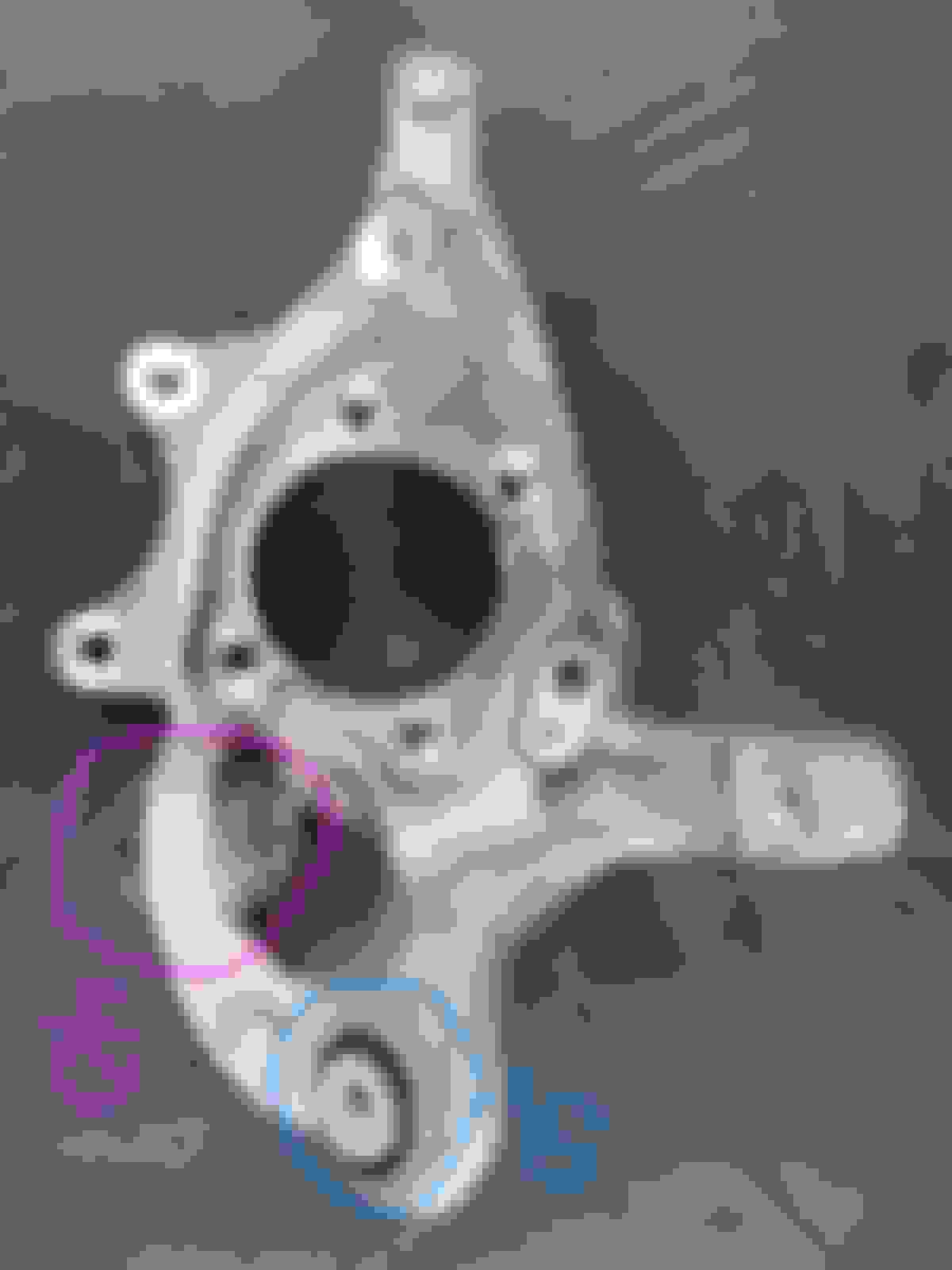
This is the only bushing with steel cylinder. The rest are ALU cylinder.
The worst bushing to work with, so much force needed to remove and install it.
Thus a proper good tool is a good investment when buying them is easy for you.
For me the importation is a big hassle.
My final/new DIY bushing tool for it is decent, in green. Not good enough, but decent.
I made a new one after I replaced my bushing.
I use it to replace my friend's W204 bushing with it and using my impact gun. If hand turn is still a nightmare.
The bolt I use is now M14, as M12 thread often get damaged from the force required to work on this bushing.
The mistake is this part of the PUSHER unit too thin, thus it bent inward
.
Two washers act like simple bearing.
.
.
I can't control the steel type machine shop uses, it is a small machine shop.
The thrust arm tool came from MB-USA and the Gedore tool is coming from Germany. I figure the tools are a good investment since my other option is paying the MB dealer $225/hr to do the work. Plus I think I can always re-sell the tools for at least half what I paid.
I'm finding out these really are specialty tools. The wheel carrier is shaped in such a way that basic bushing cups wont fit without some type of modification especially if its being used on the car.
I looked closely at the bushing and does appear to be the Lemforder symbol so thats what i'll order. I also want to use the best grease for the threads, I read Molykote G-N is good.
Without the notch the cup fits crooked against the surface of the wheel carrier at the thrust arm bushing.
And the pushing cup sits on the bushing perfectly.
Agree, good accurate tools are worth the investment.
Ur photo shows you worked on bushing #50. The easy one.
When you try bushing #40 steel body, it will be approx 300% more force to work compared to bushing #50.
Bushing #50 is aluminum body, it sacrifice itself when fighting the knuckle metal , which is also aluminum
Bushing #40 being steel body, it eats up the knuckle metal, which is aluminum....hence it requires much more force to insert and remove.
Inserting bushing #40 is more difficult than removing it....from accuracy stand point, if the tool is not accurate/good, like my 1st try on my E400 knuckle.
Mercedes SLR McLaren 722 S Is Extremely Rare Example Modified by McLaren
Slideshow: A one-of-one U.S.-spec Mercedes-Benz SLR McLaren Roadster became even rarer after a factory-backed transformation at McLaren's headquarters.


 ... it is so cheap for the database it can provide me.


 thanks for sharing