When you click on links to various merchants on this site and make a purchase, this can result in this site earning a commission. Affiliate programs and affiliations include, but are not limited to, the eBay Partner Network.
A lot of data to examine carefully and with accuracy. First bits of info, compared to my car and cross referenced to WIS:
- Our CPS/Intake cam profile overlays are identical on idle (I have a recording from a couple of months ago that I was able to use for this).
- With the info at hand, it seems at first glance the timing of control of the QV on my car is correct. However, this is a very rough estimate, derived from the 40� flat position mentioned in WIS.
- The timing of the start of your QV control does not match any of my timings (The start of a 'first' lobe does not overlap with any of my 'first lobe starts.) I would expect MB to have an identical '0' position on the lobes.
- I'm really lacking a known-good QV/CPS or QV/Inlet cam.
I been trying to find my actual 4 peaks or the TDC-s in relation to CAMshaft degree, but it is not easy because I think MED177 we are using is more complex.
I am using this part of the INTAKE CAMshaft tone wheel as reference, in my calculation. I use it as CAM-zero degree. Zero degree using start of Intake CAMshaft 2nd short rise
.
.
The WARM IDLE 600 RPM seems to be the odd one. I think, it is trying to lower pressure by overshooting past TDC/peak of the lobe.
.
.
Last edited by S-Prihadi; Apr 10, 2024 at 12:01 AM.
Reason: ADD INFO
Very useful info on that side, and some proper explanation on the workings of the HPFP.
The WARM IDLE 600 RPM seems to be the odd one. I think, it is trying to lower pressure by overshooting past TDC/peak of the lobe.
The design of the various valves in the pump do not allow for this function. There is a check valve between the cylinder chamber and the fuel outlet towards the rail. Pressure on the rail cannot escape via the check valve. There is a safety valve incorporated to allow bleed-back, but this will only function significantly above 200bar on the rail. From witnessing controlled pressure changes on my car, I gather the following logic:
- If the required rail pressure is lower than the current rail pressure (e.g. the 200 -> 150bar drop after 30s of cold idling), the QV is not controlled and pressure on the rail is gradually reduced by normal fuel conspumption of the injectors. Once the pressure is low enough, the QV is again controlled.
- Rail pressure is probably taken into account while calculating the required injector opening times, to adjust for actual rail pressure vs required rail pressure.
This bit in the info on the openecu site is very intriguing:
The FCV solenoid must be energized long enough so that enough pressure is developed in the pumping chamber to prevent the FCV from opening till the plunger begins its downward stroke. By relying on the pressure in the pumping chamber to keep the FCV closed the on-time of the FCV circuit can be reduced which reduces current draw from the ECU and limits the heating of the ECU.
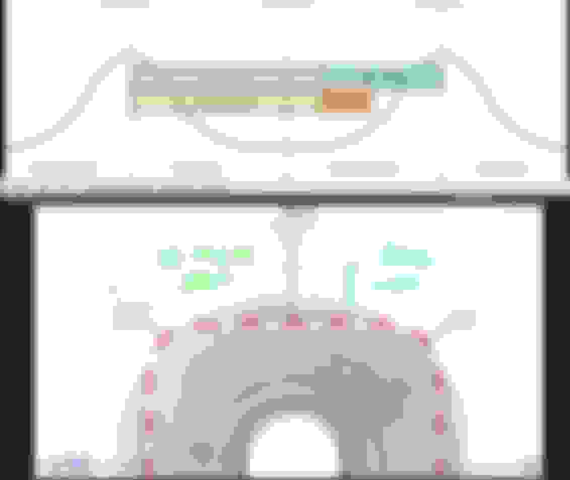
Compare this to the fuel pump drawing provided in the M276 booklet from MB:
The pump design indeed allows for this function: to prevent the FCV from opening. Note the little spring I'm pointing at with the green arrow. Once there's enough pressure in the chamber, the QV will remain closed, even if it's no longer being powered by the ECU, during that stroke. Not sure yet how this design would influence the effect of incorrect timing of the QV compared to the cam lobe position. In that scenario, the QV is closed during the downward motion of the piston, leading to very low pressure (and possible cavitation?) inside the chamber, or the piston not moving down at all, if the lower spring (the big bottom one in de drawing above) is not providing enough force to overcome the low pressure. Which would possibly lead to loud slapping noises as the cam follower would no longer be in constant contact with the plunger 4.
Such a small bit of the total engine but already so much to learn about!
I can't say that the OpenECU is using exact 100% copy of HDP5 Bosch we are using, but since it has ECU/ECM for GDI engine, I think at least on the control side of QV their information is good.
I said overshooting past TDC/lobe peak means the pump will then not allow enough downward stroke to BDC as taking in fuel.
Remember, whenever QV closes, fuel can not get into compression chamber too.
What I am trying to do is to figure out what MED177 maybe different in how it control the QV in respect to fuel lobes peak /TDC compared to OpenECU.
Because we can't access the intake camshaft bank 1 to measure their 3 or 4 peaks/TDC in respect to its tone wheel....for now.
Understanding a 4 lobe M276.8 would be the key to understanding your M276.9 3 lobe QV strategy.
I said overshooting past TDC/lobe peak means the pump will then not allow enough downward stroke to BDC as taking in fuel
Well, at the same time, we're talking about a hydraulic pump, not a pneumatic pump. And fluid cannot be expanded by a downward stroke, so if all valves are closed, I would say the pump gets stuck for that downward stroke.
It would indeed help to get a reference between cam tone wheel and cam lobes for your engine (and mine). I think on the E400 you have intake cam part number A2760500800, is that correct? There are plenty of picture on google search, showing a rough indication of tone wheel vs lobe position. Then of course we need to take into account that the angle at which the fuel pump is mounted is off by about 90� (at least on my single-pump engine) compared to the cam position sensor. And the cam signal is driven slightly earlier (~3�) before the visual position in the sensor opening. (the 0� position in your drawing is very close to 30� CKA). From picture of cam 2760500800 I think the 0� degree position you're drawing should be moved 22~45� anti clockwise. However, there are a lot of error margins in here, as these are just rough pictures, and I would have to assume the 90� offset between cam position sensor and fuel pump housing and take the difference between cam position reading and actual cam position into account.
Okay, interesting. Tonight I got the dial gauge out to measure the lobe position vs crank angle etc. I got the time to remove inlet, and the HPFP down to about 20 minutes now, getting good at this procedure unfortunately.
The lobes are exactly where WIS states where they should be. With the crank at the 40� mark, cam tone wheel indicating the overlap TDC position of #1, I find the peak of the lobe. Which means (as it's only 3 lobes on mine), the flat should be 180� opposed, so at 40� CKA after ignition TDC on #1, which is the position stated in WIS document ar0510p762004mm. So that seems to confirm once more that my cam is in good order and the problem is elsewhere. I'll recheck the earlier scoped timings of QV vs inlet cam, but first impressions shows that timing to be correct as well. Some calculations seem to indicate that the QV start closing 10� camshaft angle before the ramp up, and close at 10� camshaft angle before ramp down starts, in the scenario where pump demand is 100% (so 50% duty cycle of the PWM).
Great, good mechanical check.
Now use your Launch baby scanner and see ( engine off ) , what does it say for VVTs degree before engine start and what camshaft adaptation values is your ECM keeping now.
Now scope CrankPos vs Intake CamPos Bank 1, but you must first overcome the engine warm up period and be at the 600ish RPM warm idle or engine must run decent for 100 seconds from cold start.
After that scope Exhaust CamPos Bank 1 vs Intake Bank 1 CamPos at warm idle.
After that scope again Bank1 Intake CamPos vs Fuel QV actuation.
This morning I did a double check to confirm lobe positions, and int confirms my reading of yesterday.
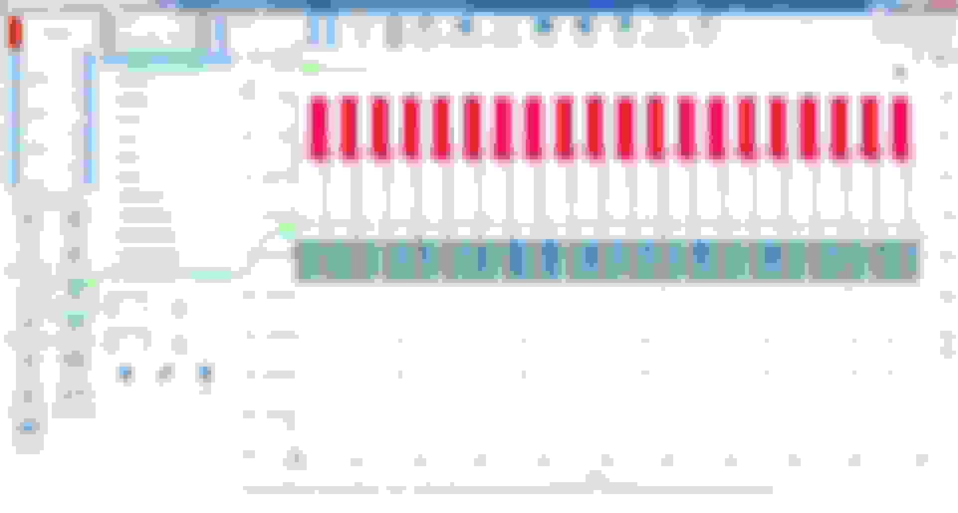
Unfortunately, in this condition the car idles so rough that it's really impossible to the engine to warm up. So these are the readings I have to work with. Before I got my dial gauge out yesterday, I scoped the intake cam position versus QV current with non-mercedes branded Bosch HPFP attached. Strangely, I got very odd readings on the current, which of course I forgot to store on my laptop. Darn. The current profile of the MB branded pump is in post #30 above, a logical profile with a short high-current burst to get the piston moving, then a steady lower current to keep the valve shut.
With the 'other' Bosch pump on the car, I got a very different profile. Very stupid not to store this, so here's a rough drawing of that profile:
As you can see, current showed both positive and negative values. In hindsight should have investigated this further with some voltages readings, but it might indicate that one of the pumps is having issues with the QV, further messing things up. Currently searching various forums for a current trace of a known-good HPFP QV!
Interesting current waveform information on the non MB branded HP pump.
It goes to show that MB probably may need its own special requirement because they have some technical reason for it and Bosch complies.
I regretted that when I made the test wire for HPFP QV I did not scoped its current waveform.
Now its too difficult to access the wiring loom to do current waveform , good thing my voltage waveform can still be used as baseline for future works.
Fascinating difference isn't it? The solenoid coil in the pump is supposed to be just a long piece of copper wire. So what could create this differences in currents in 2 pumps that are supposed to be identical? Some ideas:
- I messed up once again scoping this. Though, with a current clamp I don't see how I am supposed to mess this up.
- The QV valve itself is stuck in one of the 2 pumps. The movement of the steel rod will create differences in the magnetic field and currents. See the negative voltage spike after closing the valve, or the typical current on-ramp profile of solenoids in general. Differences in movement of the steel rod will influence currents and possible voltages as well.
- The coil in the solenoid is damaged somehow, maybe when testing the QV with a separate 12V connection. Though the internal resistance of both coils are pretty similar.
- The Bosch ECU is very very smart, identifies the QV type and produces a different control strategie. This is highly unlikely to me, but alas, cannot be ruled out.
Now of course, having 2 pumps behaving differently, there is for now no easy way to tell which behaviour is right. Best right now would be to try them both once again, and do a deep dive on voltages and currents etc. However, the high pressure fuel lines can only be loosened/tightened a limited amount of times before I have to replace them, at considerable cost (for just a bit of piping). And I'm not sure yet if it would make me any wiser and closer to solving my issue.
Things I do know right now, is that, besides the pump itself, all other things tend to check out okay:
- Fuel flow and pressure on the low pressure side are okay.
- Fuel filter is new.
- Fuel is clean (now).
- Cam timing is correct.
- Cam lobe for the HPFP is in the expected place.
- Control of the QV matches the cam lobe position.
- Injectors seem to be leak-free, as the rail holds is pressure after engine shutoff.
Would there be this very exotic chance that I happen to have 2 new but broken HPFP's (albeit one used, without issues, for 800miles, the other being a non MB-branded one)? Could there have been a weird underlying issue in the fuel system that was able to kill a total of 3 pumps in quick succession?
Try a single channel and scoped the QV in voltage for both pumps. If you are worried 2nd channel get too much noise.
Use a 10:1 attenuator, you have it right ?
Yes, at some point in time you need to replace those HighPress pipes.
The ferrule MB uses is not as good a Swagelok twin ferrule. The pipes itself is OK, the ferrule is the one taking the beating.
Bu the ferrule relies on "damaging" the pipe OD to maintain sealing integrity, and if a single ferrule they sometime "spin" a bit.
Fascinating difference isn't it? The solenoid coil in the pump is supposed to be just a long piece of copper wire. So what could create this differences in currents in 2 pumps that are supposed to be identical? Some ideas:
- I messed up once again scoping this. Though, with a current clamp I don't see how I am supposed to mess this up.
- The QV valve itself is stuck in one of the 2 pumps. The movement of the steel rod will create differences in the magnetic field and currents. See the negative voltage spike after closing the valve, or the typical current on-ramp profile of solenoids in general. Differences in movement of the steel rod will influence currents and possible voltages as well.
- The coil in the solenoid is damaged somehow, maybe when testing the QV with a separate 12V connection. Though the internal resistance of both coils are pretty similar.
- The Bosch ECU is very very smart, identifies the QV type and produces a different control strategie. This is highly unlikely to me, but alas, cannot be ruled out.
Now of course, having 2 pumps behaving differently, there is for now no easy way to tell which behaviour is right. Best right now would be to try them both once again, and do a deep dive on voltages and currents etc. However, the high pressure fuel lines can only be loosened/tightened a limited amount of times before I have to replace them, at considerable cost (for just a bit of piping). And I'm not sure yet if it would make me any wiser and closer to solving my issue.
Things I do know right now, is that, besides the pump itself, all other things tend to check out okay:
- Fuel flow and pressure on the low pressure side are okay.
- Fuel filter is new.
- Fuel is clean (now).
- Cam timing is correct.
- Cam lobe for the HPFP is in the expected place.
- Control of the QV matches the cam lobe position.
- Injectors seem to be leak-free, as the rail holds is pressure after engine shutoff.
Would there be this very exotic chance that I happen to have 2 new but broken HPFP's (albeit one used, without issues, for 800miles, the other being a non MB-branded one)? Could there have been a weird underlying issue in the fuel system that was able to kill a total of 3 pumps in quick succession?
Technical notes always tell us that they do not want to overheat the QV coil, hence there is a way to energize it to make it last long.
I do not think the ECM would be the QV killer....unless some input is not proper.
Maybe possible once a QV electrical "signature" is out of spec, ECM simply ignore it or to protect itself ?
J,
Perhaps the difference between MB branded HPFP QV is the back EMF diode. Or flyback diode.
All solenoids with coil will produce back EMF, including relays.
Negative current is the back EMF of a coil.
Some MB models of HVAC valve do have built in diodes and some does not.
So the HVAC computer N22/7 is matched to such solenoids. So the diode could be at N22/7 module or at the HVAC solenoid.
Wrong selection of HVAC solenoid will make compressor wont work. It was documented in one of Pine Hollow video on a GLE chassis. Owner did not buy a proper MB HVAC solenoid.
Further digging this weekend, and some interesting findings.
Trying various things with the HPFP, timing etc, I've for now concluded that the HPFP function is probably okay(*), and there might be an issue further downstream, between HPFP and cylinders. So I set out to further investigate the relation between injector timing and fuel pressure. As I have the current clamp available now, it's pretty straightforward to measure injector timing. The rail pressure sensor can be back probed from the ECU connector. Let's go:
First capture. Blue line is injector #1 current. Red line is pressure sensor on the fuel rail. Time is right after startup of the engine.
Okay, this is strange. During injector #1 operations, the fuel pressure does not go down. However, later on it does. Getting the firing order from this engine (1,4,2,5,3,6) it seems there is something weird going on. Let's try injector #4, which sprays directly after #1:
More info on the blue trace: the injector is opened by the negative current spike, it's closed by the positive current spike. What you can clearly see happening above, is the fuel pressure in the rail drops during operations of this injector. Let's examine #3 and #6 together, first injector is #3, second is #6:
Okay, this is wrong. Some checks confirmed this: on firing injector #1, #2 and #3, fuel pressure is not impacted. On firing #4, #5 and #6, the above effect is visible. That's a complete bank, and actually the bank with the rail pressure on it. Hmmm.. I get a pressure issue only on these injectors??
Let's give it a try with injector 4,5 and 6 disconnected, see what happens then:
Hard to see here, but over the whole trace, there is no drop in pressure. Actually, the pressure rises to 200bar, with the engine running reasonable, insofar as possible with only 3 cylinders active.
So, this is interesting! This examination of the relationship between injector vs pressure gives a whole new insight, clearly there is an issue on bank #2.
There's plenty of fuel on bank #1, while there's starvation on bank #2. This puts a whole new light on my previous issues!
Take for example below graph, fuel pressure starts at 200 bar (cranked with all injectors disconnected). Then I started the engine, pressure drops rapidly. At the lowest dip, the engine stalls. Then pressure starts to build again, and the ramp-up slowly declines till a steady line:
Now think of the setup of the fuel rail. The pressure sensor is at bank #2. What if there is a very severe blockage in the fuel line to bank #2, or in fuel rail #2? When almost completely blocked, rail #2 can be rapidly depleted of pressure once the injectors are firing. Or, after engine shutoff, the pressure between rail #1 and rail #2 will level over time, which would lead to the exact above graph. The higher the pressure difference between rail #1 and #2, the more rapid the equalisation takes place.
Another interesting view, at engine idle. Rail pressure @150 bar. Two times I press the throttle, and pressure drops in rail #2. The pump 'fights' to bring the pressure back to 150 bar, but overshoots twice.
Again, think of a severe blockage to rail #2. Pressure in rail #1 would be at >200 bar and pressure in #2 would steadily rise. Once #2 crosses 150 bar, the HPFP will turn off, however, as the pressure in rail #1 is way higher, the pressure in rail #2 will overshoot..
I think I'm finding a plausible explanation for the behaviour I've been witnessing! Let's get the high pressure fuel line and rail #2 removed from the engine.. Will keep you posted on my findings!
(*)
I did some further scoping on the QV current. It seems my current clamp sometimes acts up and gives these weird #59 readings. With proper grounding of the scope leads, this disappears and becomes a normal reading like post #30.
2015 SL400 (M276 Turbo), 2014 C350 Sport (M276 NA), 2004 SL500 (M113), 2004 Audi TT225 (BEA)
Originally Posted by S-Prihadi
Piezo injector if power is loss during engine running is dangerous, it may stuck open.
Piezo need electrical assistto close and open. There is no spring like oldie electro-solenoid type injector.
The piezo stacks change shape using electricity, hence its so called Open and Close needs electricity in "opposite" way. https://www.techtips.ie/Autobiz/test...njectors-1.pdf
@S-Prihadi Not sure if the linked document addresses the final state of the piezo injector when the engine is NOT running. And do we know if the XENTRY-run compression test shuts off fuel or simply holds the injectors close?
The ECU is supposed to shut the injectors before engine shut-off. Otherwise the rail would empty itself into the cylinders, which is unwanted of course.
Attach your scope captures, don't just screen shot.
I cant see the timing and the voltage or current values.
I don't even know the voltage limits of the fuel pressure sensor, never measure it.
Is it a 0.5V to 4.5 V ? So zero volt or 5V is an indication of fault/s.
Is it linear 1 volt = X Bar of pressure ?
When you back probe the fuel pressure sensor, the pressure section, note the voltage when at 5-6 BAR and when at 180 BAR.
From there at least if the value is linear it will be helpful.
If indeed fuel rail bank 2 is clogged, I wonder what damage it also impacted to the HPFP ?
I mean the dirt must be a lot.
ADD : Very first few seconds of start COLD, injectors fire 4 times.
Triple injector firing is when engine still cold.
Later it will do twin firing when engine more warmed up.
Single firing when engine is already warm enough.
ADD: Very first few seconds of start COLD, injector fire 4 times. I do not know if this will apply to M276 non turbo...or not ?
........
Attached a warm engine injector voltage and current. Also COP current, see the notes.
I am using differential probe for the injector voltage.
Last edited by S-Prihadi; Apr 20, 2024 at 10:10 AM.
@S-Prihadi Not sure if the linked document addresses the final state of the piezo injector when the engine is NOT running. And do we know if the XENTRY-run compression test shuts off fuel or simply holds the injectors close?
I am sure during compression test, Xentry simply do not power the injector at all and also no power to the COP.
I never bother to check though...but it is logical
Attach your scope captures, don't just screen shot.
I cant see the timing and the voltage or current values.
I don't even know the voltage limits of the fuel pressure sensor, never measure it.
Is it a 0.5V to 4.5 V ? So zero volt or 5V is an indication of fault/s.
Is it linear 1 volt = X Bar of pressure ?
When you back probe the fuel pressure sensor, the pressure section, note the voltage when at 5-6 BAR and when at 180 BAR.
From there at least if the value is linear it will be helpful.
If indeed fuel rail bank 2 is clogged, I wonder what damage it also impacted to the HPFP ?
I mean the dirt must be a lot.
I'll try to upload the psdata file. I've only got Picsoscope 7 T&M, so you cannot find the right crank angle info etc. But the basics are there.
The rail sensor reads ~0.7V at 7.7 bar and ~1.36V at 61bar. I've set the scaling to 2V to get as much detail as possible, as my scope is an 8 bit version.
For now I'm trying to understand the basic plumbing of the rail. The pipe running into the rail is not an open line:
This is the fuel entry point into rail #2. I was expecting the small hole to be open into the rail, but it's not. A needle won't protrude into the rail. Air passes this opening so there is way through..
Aha, good info . They need smallest volume possible in fuel rail, otherwise the pressure will collapse.
So the fat fuel rail body is for "mounting" of injectors only. Inside it is small pipe size for fuel delivery.
700 millivolt for 7.7 BAR, I think this sensor starts at 0.5V, but I can't correlate 61 BAR to the 1,360 millivolts. The result does not match.
The HPFP pump actually can also fail at its output check-valve and/or at the pressure relief valve, come to think about it.
Without the check-valve doing its pressure maintaining properly, there will be poor pressure build up at the pumping chamber.
Or if the pressure relief valve weakening and fuel is suck back to compression chamber during piston downstroke.
If those 2 are purely spring operated, surely someday it can break too.
Just something to think about.
BANK 2
How easy for air to be blown into fuel big rail and exit at the 3 injectors hole , tested 1 by 1 per injector hole ?
Same question for the fuel pipe from HPFP to the bank 2 fuel big rail.
Inner diameter of the rail is actually ~7mm, while being 25cm in length. I think that gives 1/100 of a liter of volume in the rail.
I've blown air through the high pressure line, from the connector on bank #1 to the connector on bank #2, with the HPFP attachment closed of with my thumb. Pretty decent flow (testing at ~7 bar air pressure from my compressor).
On rail #2, there is the opening of the pressure sensor on one side of the rail, so I can peek into the rail, and put air pressure on that side. With all injectors still attached, I get a reasonable amount of air out of the union attachment on the rail. However, the other way round, the air flow seems more limited. Of course, if something was clogging up the system, I may have accidentally already removed it. So it's a bit hard to conclude if there is still a problem.
I'm currently trying to get a small thread through the system. Got my vacuum on the opening of the rail sensor, and trying to 'suck' a thread through whatever opening is there. So far no luck, it must be a convoluted path somehow.
Sometimes cleaning inner pipe is good to use liquid, better than air in terms of pushing power.
Do you want to try using cooking oil or similar lightweight non harmful oil ?
Pipe ID 7mm, that is the same my 225/335 BAR dive compressor HP air pipe.
Not sure what you're aiming at. The rail inner pipe is clean, with a light I think I can spot the other side internally. That bit is clean. Since the union connector to the rail is close to the pressure sensor location, it's very easy to inspect that bit visually. And that bit is unobstructed. So if there is a blockage, it's either in the convoluted entry into the rail, or in the fuel line between the HPFP and the rail. I'll try to get a picture of the inside of the rail.
Or, if I'm really unlucky, the fuel line is not attached straight and blocking the very small opening into the rail itself.
Here it is. The little protruding rod is at the location where the fuel lines attached to the rail it seems. This seems to be the place where fuel enters the rail.
Mercedes SLR McLaren 722 S Is Extremely Rare Example Modified by McLaren
Slideshow: A one-of-one U.S.-spec Mercedes-Benz SLR McLaren Roadster became even rarer after a factory-backed transformation at McLaren's headquarters.


 . They need smallest volume possible in fuel rail, otherwise the pressure will collapse.