When you click on links to various merchants on this site and make a purchase, this can result in this site earning a commission. Affiliate programs and affiliations include, but are not limited to, the eBay Partner Network.
and if so where would I get the signals for this interface for this wiring harness that clamps around the Hi and low CAN Bus (instructions say it�s near the ignition key but that�s it)
I found this thread when I was trying to find out the same thing as blu60, but there was no answers to be found here. I still managed to complete the installation and I really hope that blu60 also have done that. Now I know there is at least one member here trying to find out how to do this, so I thought I should share how I did this.
First a disclaimer: English is not my native language. Grammar might be funny and I might not know all the correct terms for things, but I hope you all understand anyways.
The Cannect CanM8 installation manual for G-Class 2012> says under �Vehicle CAN Bus Location� that �The CAN wires are located at the Ignition Barrel� and then �CAN HI = BROWN /RED, CAN LO = BROWN�.
That�s all, nothing about how to find the wires and connect them. I did a lot of searches on the Internet, but couldn�t find any good manuals/tutorials. I found that on many cars you can connect at the ODB connector. That seemed easy, so I found out what cable are CAN HI/LO and tried that, but it didn�t work.
Then I went to my local MB authorized workshop and asked how to do this. First they explained that my car has three separate CAN bus systems. The one at the ODB connector is not the same as the one at the ignition barrel. So, I had to reach the cables behind the ignition switch.
The workshop printed two manuals for me, one for how to remove the panels under the instrument panel (AR68.10-P-1500GW) and one for how to replace the ignition switch (AR80.57-P-1000GW).
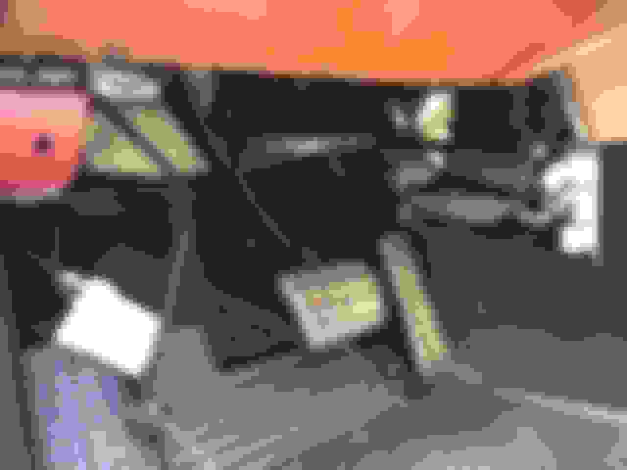
I didn�t take any pictures of this, but removal of the panels are pretty basic. Start with the small on the tunnel, three screws and just remove it. Then there is three screws to remove at the upper edge of the large panel. Pull the cover down, can be a little tricky with the air duct inside. ODB connector have to be removed from the panel. Depending on options there is some other cables to disconnect to remove the panel. When you are done it should look like this.
The twisted pair coming from the ODB connector is from my (failed) attempt to connect there.
Now it�s time to find the cables behind the ignition switch. First completely extend steering wheel toward rear. Then it says you should detach ground line from battery, but I didn�t. Do as you like, but don�t blame me if something goes wrong with your electric system.
The panel with the bellow around the steering column can now be pulled back. Be careful to not drop the knob for the instrument light control inside the panels under (don�t ask me how I know this).
The manual I mentioned above (AR80.57-P-1000GW) then describes how to remove some bolts and then just losen some to be able to remove the ignition switch. I found that I didn�t have to remove the switch, just two of the connectors on the switch.
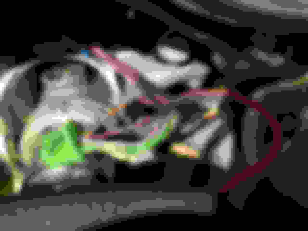
I disconnected the blue and the green connectors and pulled out the cables as much as possible. The CAN HI/LO is located in the green connector, but you can pull the cables out more if you also disconnect the blue connector.
Then I used a small snap-off blade knife to carefully remove 10-12 mm (1/2�) of the insulation on the two cables (brown/red and brown).
As the cables that come with the device is pretty short I used a piece of speaker cable as extension. I twisted the ends of these cables around where I removed the insulation.
Then I soldered on the cables to secure the connection.
Insulated first the separate cables with �electric tape� and then around all of the cables.
Connector when I was done. Both connectors were then installed back on the ignition switch.
I routed the cable along the air duct and attached it with tape to the duct. I crimped one male and one female round connectors on the wires and tied the cable up with a cable tie.
The panel around the steering column can now be installed back, don�t forget the knob for the instrument light. The panels under the instrument panel stayed off until I completed the rest of the installation.
Now it�s just the rest of the installation, but this is the most difficult part. If there is any interest for it I can write a little more about this another night.
This is the first time I'm posting images in this forum. I don't know if I found the best way to do it. I uploaded the images to an album, but then I couldn't find an easy way to put them in my post. I went to the album and opened my album, right clicked on one image and choose to copy the image. Then I had to close the album to get back to my post and paste the image, and then repeat for all other images. Isn't there an easier way to do this?
On the left side (drivers side) of dash, remove the side cover and your can line connectors are in there. they are all labeled what they go to with abbreviations. Just went through all of this when repairing the flood g wagon that i bought.
In addition to the CAN bus cables the device need power supply and connection to the relay that will turn on the light. I bought a complete kit with relay, cables and one fuse. Fuse for the power supply to the CAN bus device was not included, so it is not shown on the image below.
As can be seen on this image there is a switch to be installed somewhere at your panel, if you want to run with high beam without your additional light. I decided to change the wiring a little, so these wires could be used to supply the CAN bus device also.
In the lower part of the last image in my previous post you can see a grey hose on top of a part of the original cable harness. The grey hose is a 8 mm hose for pneumatics that I used to protect the thin wires when routing them to engine room.
As it is a German (Austrian) car it feels good to know that the hose is "T�V GEPR�FT"!
As the battery connection in the engine room is on the right side of the car I had to go cross somewhere. I looked at the options to go cross in the engine room, but couldn�t find a good way to do that.
Soon after I bought this car I had my local workshop install a system for electric (240 V) pre-heating of the engine and the inside of the car, including battery charger, timer and remote start (of the heating system, not the engine). DEFA WarmUp is the name of the system: https://www.defa.com/electrical-preheating/
Now I checked where they had pulled the cables that goes inside the car and found them going down with some original cables behind a heat protection shield on the firewall on the right side of the engine, and then went inside the car.
I removed the panels also on the passenger side and folded the floor mat back to find where the cables came in. On the below image you can see the original cable coming through a rubber strut and the cables for the heater and my grey hose coming besides.
They had sealed with some soft black sealant, so I could make a hole with a screwdriver and press my hose through this hole and then press the sealant around it.
The small device under where the cables come in are a part of this pre-heating system.
At the battery post in the engine room there was already one extra fuse for the DEFA system, now I added two more.
If you look down behind this you can see my grey hose coming up with the wires for the light. Here are also another box for the DEFA system and some large cables for it.
To pull three thin wires through a hose might seem easy, but it isn�t! The wires are made as a flat cable, with the wires side by side. I tried to put a thin steel wire (the type used in gardens) through the hose, connect to the wires and then fold the wires and pull the steel wire at the same time, didn�t work. Not even with some lubricant.
To make the hose straight I taped it to a beam of the frame on my boat trailer.
I split up the three wires on the part that was supposed to be pulled through the hose. Connected them to the steel wire and now it was possible to pull them through the hose.
I didn�t split up the wires longer than needed, to make it look better in that end.
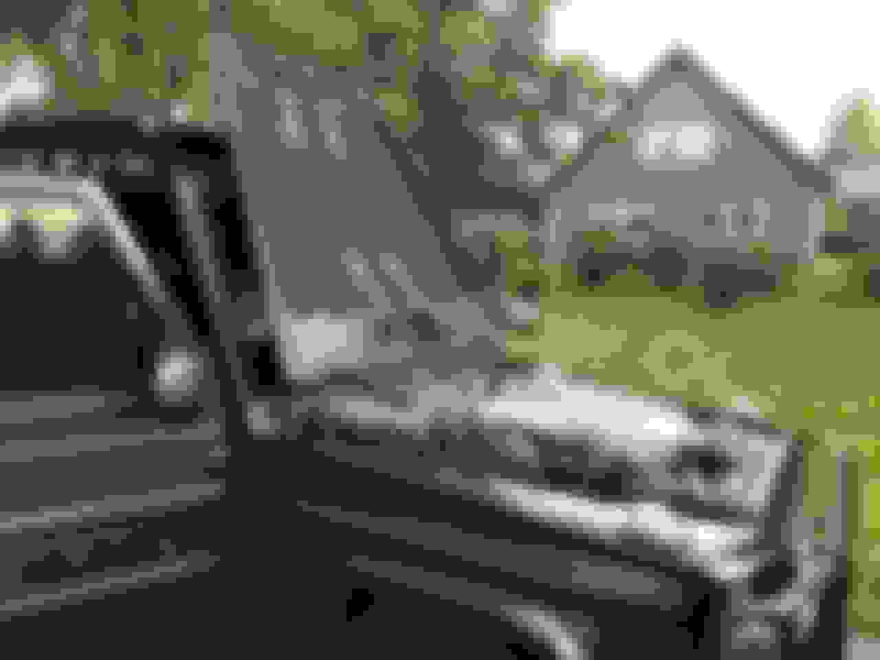
When working in this part of the engine room I recommend to open the hood all the way.
The brush guard has not been there since the truck was new. It was delivered with the "standard" AMG options, with 19" wheels. Then some previous owner have made it look like a G63 Edition 463, with 21" wheels, new front etc. I assume the brush guard was installed, and painted, at the same time.
Mercedes SLR McLaren 722 S Is Extremely Rare Example Modified by McLaren
Slideshow: A one-of-one U.S.-spec Mercedes-Benz SLR McLaren Roadster became even rarer after a factory-backed transformation at McLaren's headquarters.