When you click on links to various merchants on this site and make a purchase, this can result in this site earning a commission. Affiliate programs and affiliations include, but are not limited to, the eBay Partner Network.
I've had a tow bar / trailer hitch installed on my '06 GL500; VIN WDC1648861A140229. The car is European (Swiss)
It's an aftermarket kit from Westfalia, with a CAN specific wiring set from a brand called ECS (Link to installation manual) which terminates in a 13 pin Jaeger connector.
The firm that did the hookup is very well known; but they weren't able to activate/code the set so I took it to my independent.
He was able to activate the hitch, and contacted the dealer to add the hitch to the configuration, but couldn't get the switched (+15) 12V to work; this is to power consumers like a battery charger or fridge in a caravan. His diagnostic system shows code 914B; relay F4KL (30X) is defective, absent or the feed is interrupted.
He provided a printout from DAS showing trailer recognition active, and this error code current.
The switched 12V, according to the manual, is connected to Fuse 72 in the rear fusebox. Normally, I believe, this fuse would be powered by relay F4KL. There was no relay in place before the hitch was added so the independent had added a relay (A000 982 7723) to position L on the fuse box.
I didn't want to keep throwing money at the independent and the dealer doesn't have time until 2 weeks from now so I've started troubleshooting and have found several useful resources, however none have the exact same configuration and I don't have access to wiring diagrams for the GL. First thing I did was try a different relay because I'd seen conflicting info on what should be in that position. I tried a Hella version of A0025421119, but it made no difference.
Looking at the fusebox, I measured 12V at relay L (no matter whether the ignition was on or off) on pins 1 and 5, with pin 3 showing connection (0 ohm) to fuse 72. I assume pin 5 would be connected to ground controlled by SAM or similar, but am not sure. At any rate, I didn't measure any connection to ground there.
Fuse 70 is delivering 12V (+30); fuse 72 is not powered under any circumstances.
Any help greatly appreciated; particularly:
-Is it correct F4KL should provided switched 12V (+15) to fuse 72, and if so; what are the conditions for the relay to be powered?
-Is there another simple way to provide switched 12V from the rear fuse box are; fuse 72 is connected directly to the trailer connection so in theory any safe switched fuse-protected 12V connection would provide the functionality I need?
-Can someone provide the wiring schematic to the fusebox?
Relevant info:
Fuse box part nr A1645400572
SAM part nr A1649005101
Thanks in advance, Jay
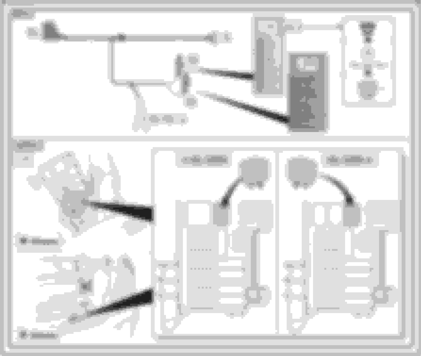
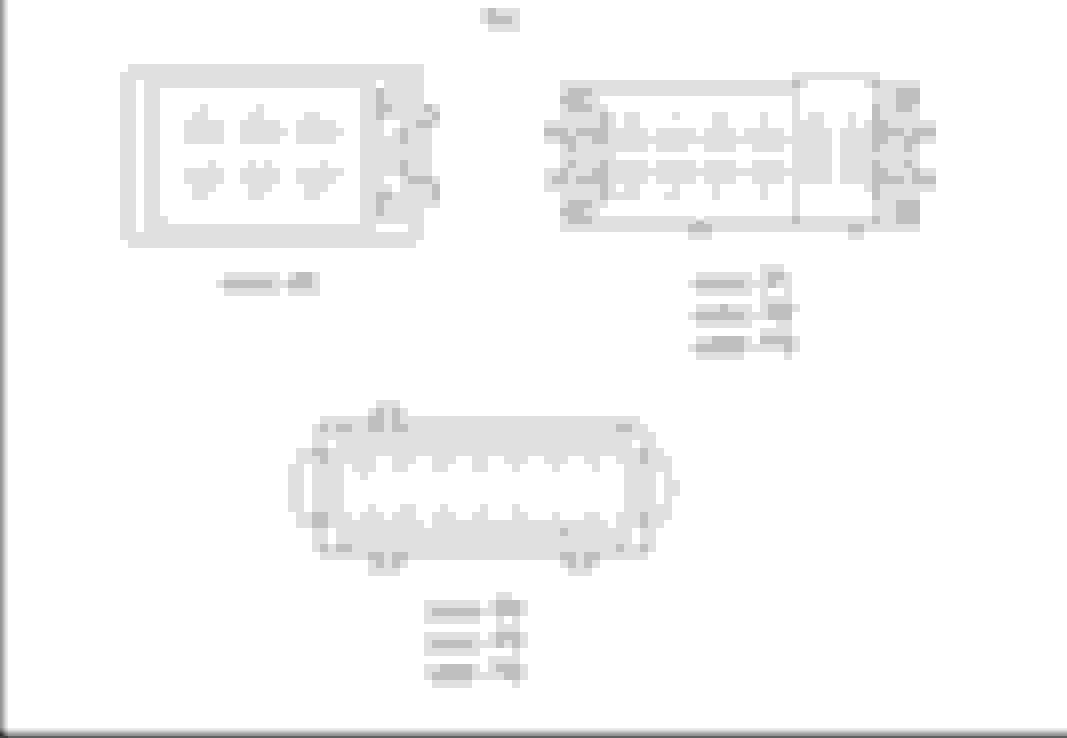
Installation manual; my fusebox is as per the left example. Trailer fuses; +30 to fuse 70, +15 to fuse 72
Anybody able to help? Any help greatly appreciated; particularly: -Is it correct F4KL should provided switched 12V (+15) to fuse 72, and if so; what are the conditions for the relay to be powered? -Is there another simple way to provide switched 12V from the rear fuse box area; fuse 72 is connected directly to the trailer connector in my application so in theory any (safe) switched, fuse-protected, 12V connection would provide the functionality I need? -Can someone provide the wiring schematic to the fusebox?
I�ve verified that the trailer lights all work, and that trailer recognition functions:
The car senses when a trailer light is broken
The rear Park Distance Control is disabled when a trailer is plugged in
I haven�t checked yet but assume the air suspension will behave as expected with a trailer attached.
noting the above, it seems the trailer hitch is coded correctly with the exception of F4KL / circuit 30X working as expected.
for now I�ve just piggy backed of of fuse 45 (cigarette lighter) for the trailer accessories. To be honest I�d rather wire trailer accessories to only work once the engine is running rather than when the ignition is on but I�m not sure whether there is an easy option to do so?
I�m still keen to get the relay to work but not sure it is worth a trip to the dealer unless it�s an easy fix.
I really think you have a coding issue. The rear SAM, Instrument cluster AND Central Gateway must ALL be coded for your trailer hitch "present" or things will not work properly. I would only trust a dealer or indy with a factory Xentry computer to do this. The rear SAM activates relays for the trailer based on CAN signals from the other control units telling the SAM that a trailer hitch is installed.
Thanks for the detailed information @E55Greasemonkey , very much appreciated!
Do you have an image showing which of the rear SAM connectors is P4; I can�t find one.
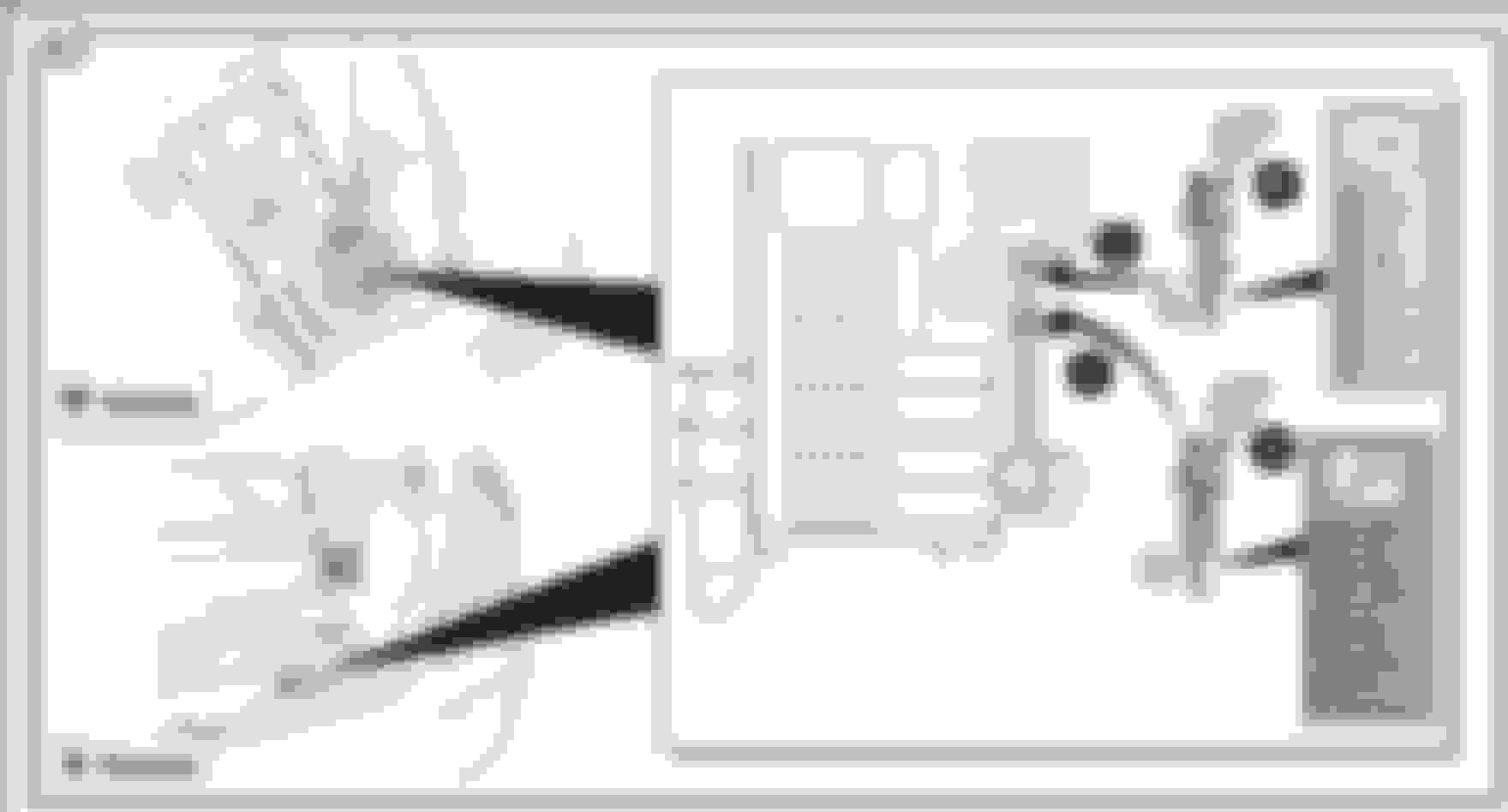
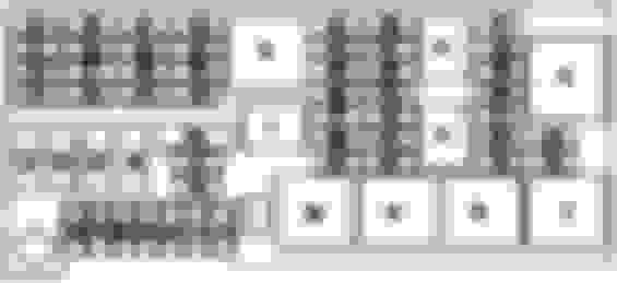
On relay U; I don�t have this in my fusebox; I believe this was only on fuseboxes of slightly later modes. My fusebox is shown on the picture in the opening post and is configured like this: Fusebox as installed in my car
What I�d like to do next is check whether the connection is at least complete (is there a wire at P4 pin 1) and whether the SAM is trying to switch relay L (does P4 pin 1 go to ground when the ignition is switched on).
If not then I�ve checked all I can and I�ll take it to the dealer as you suggest to check the coding.
I looked everywhere and cannot find the P4 pin #1 in any wiring diagram as it relates to the SAM. I found P4 with many other pins except pin 1. I would guess it's not shown because it's simply a signal out from the SAM to fuse box to trigger that relay, and the wiring diagram would only show that symbol that MB uses which looks like a diode, but indicates internal electronics that control the signal, meaning there's no wires to check... It's simply an internal function of the sam. I looked at my fuse box (2008 ML350) but it's different from yours. I also thought maybe you need a relay installed in one of your empty slots at the top of your fuse box. What letter designations do those empty spaces have? It should be marked in your fuse box, look closely where the relay sits.
Last edited by E55Greasemonkey; 06-08-2022 at 10:23 AM.
Thanks again @E55Greasemonkey ; I've made some progress based on your info.
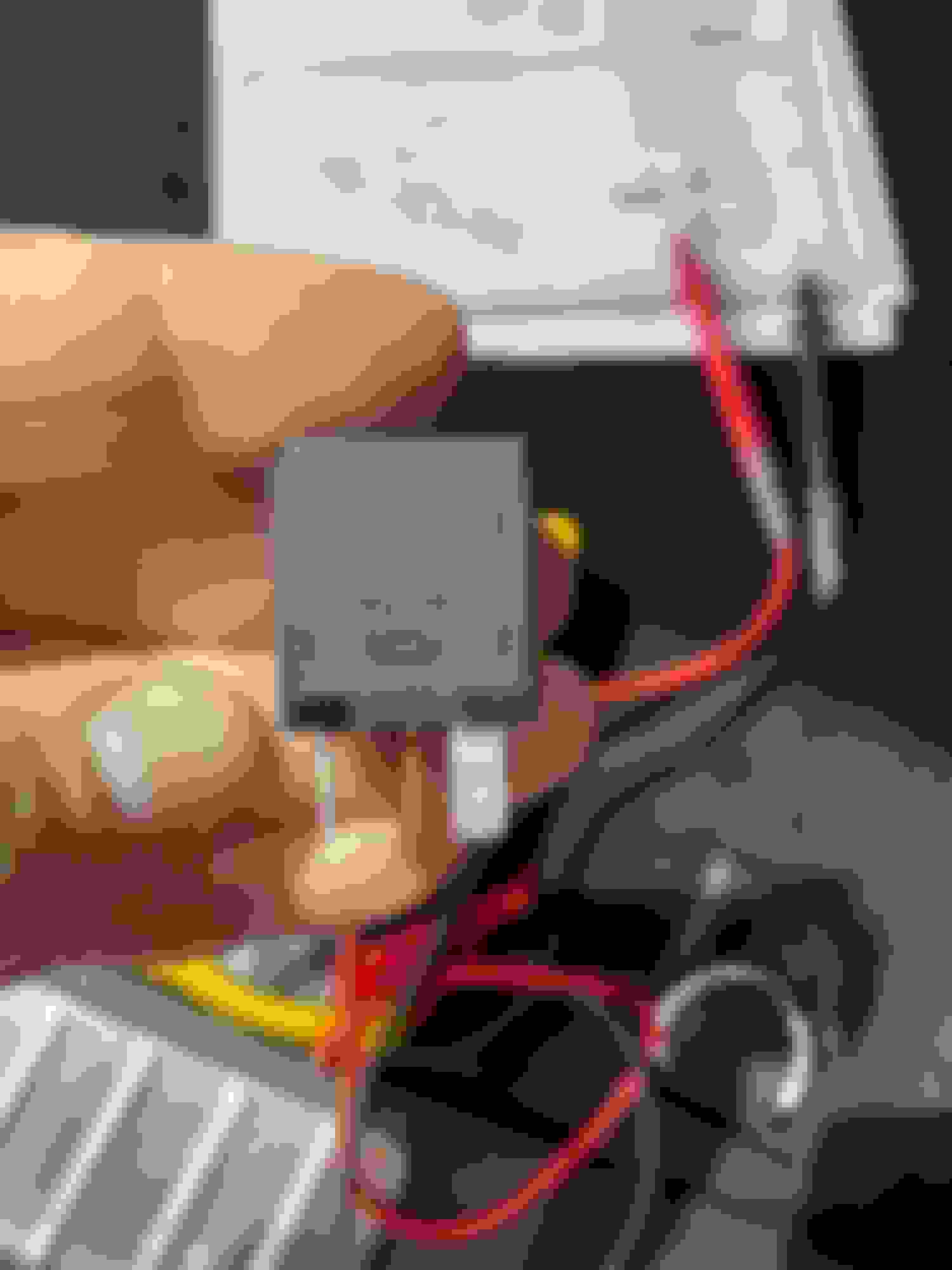
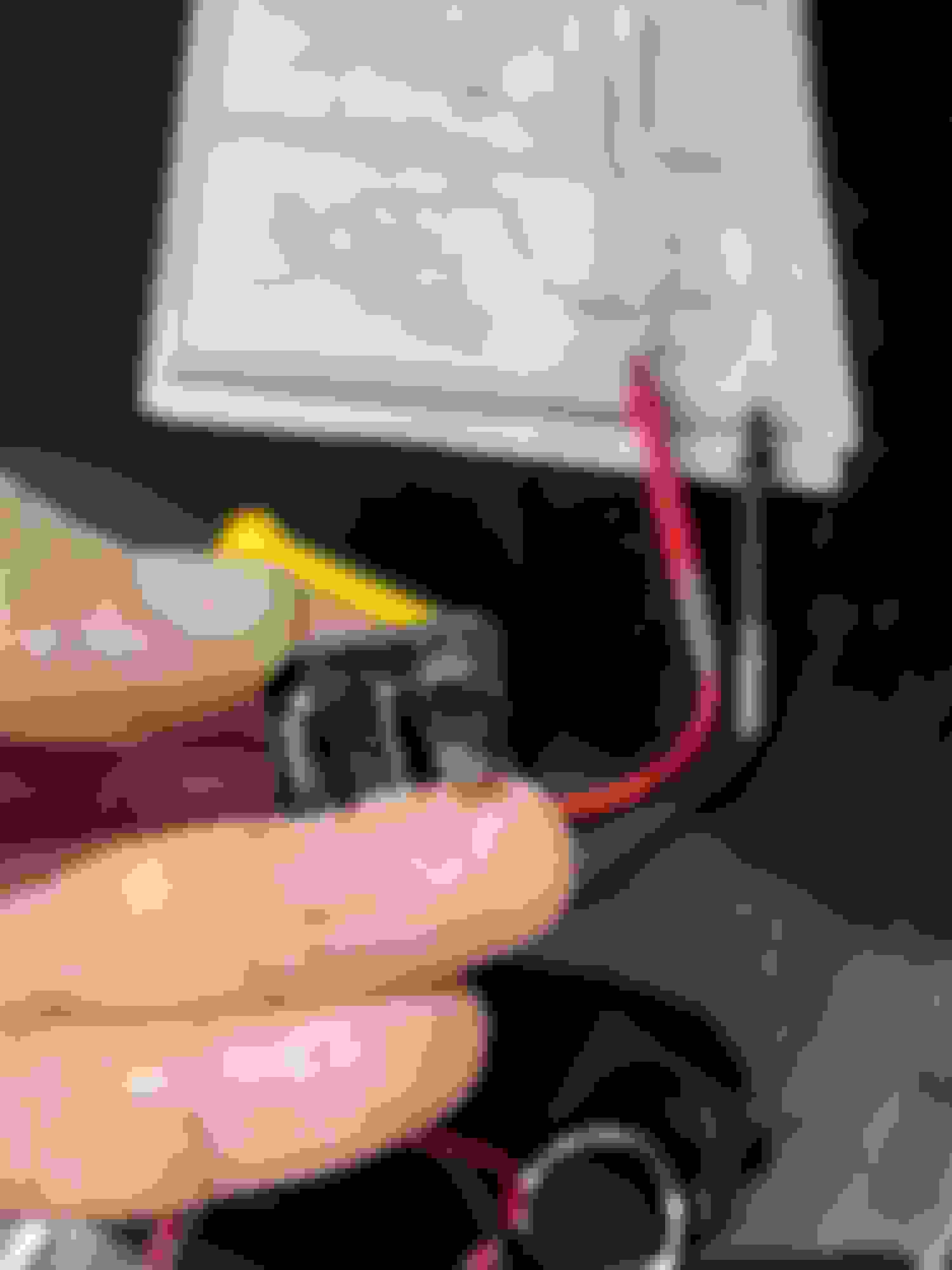
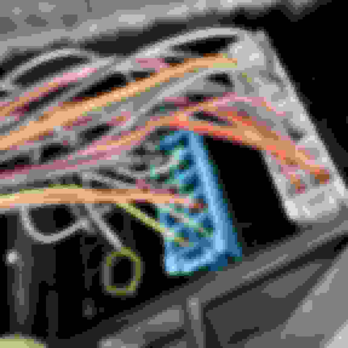
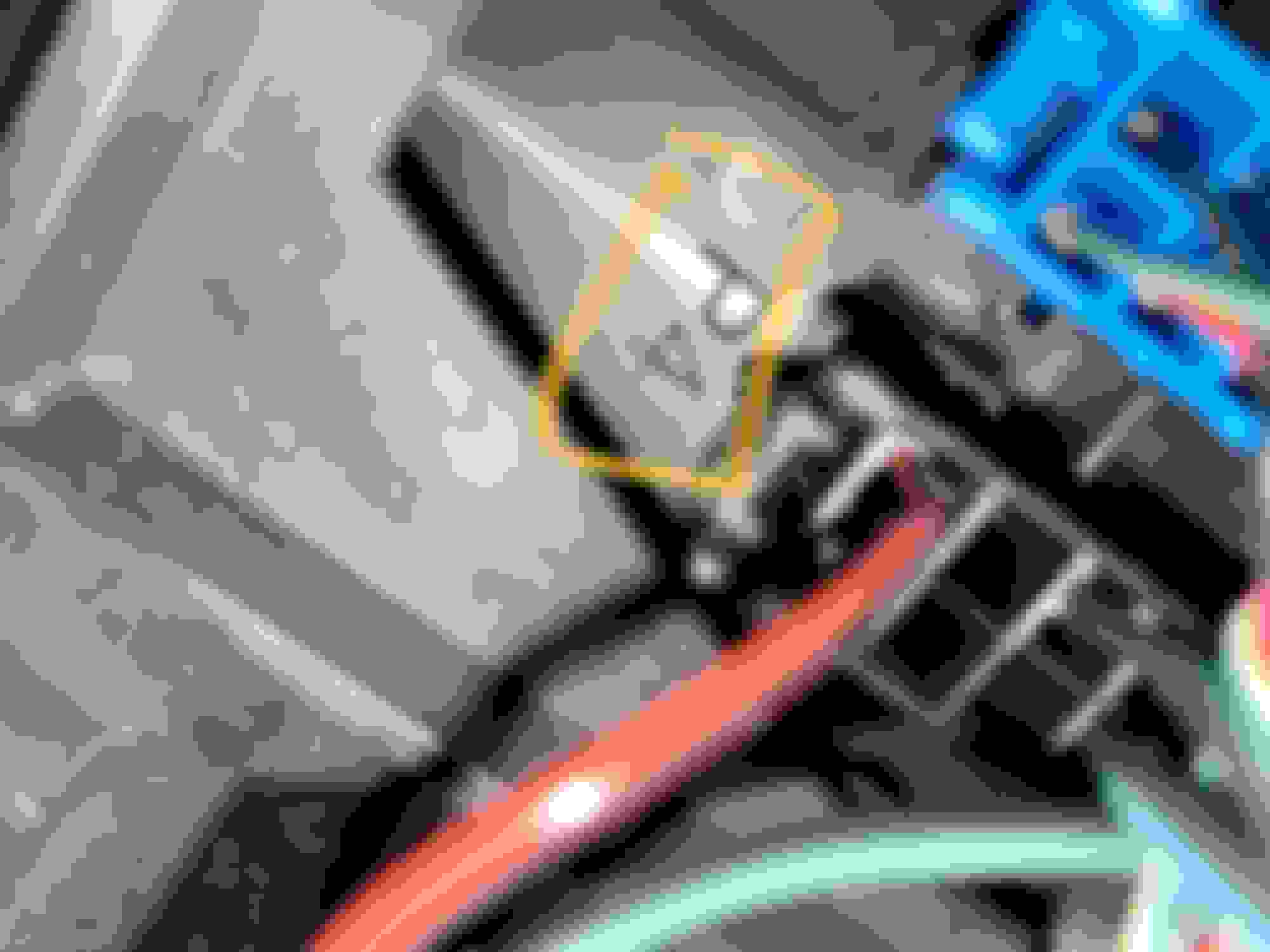
Connector P4 is in fact one of the connectors on the rear of the Fusebox; and pin 1 is indeed connected to terminal 85 of relay L from the diagram you sent (measured to verify).
Unfortunately on my car, there is no wire going into the connector for pin 1 on P4; it's empty.
I had heard anecdotally that in some cases a wire needed to be connected, but I haven't seen this in any procedure manuals?
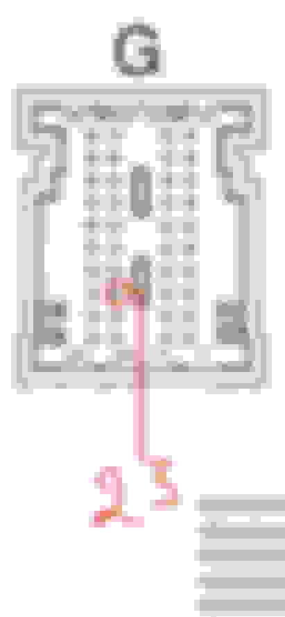
Do you have any idea where the wire that should be in P4 pin 1 should be routed/connected? Or any idea how I could find out? I can imagine it would be to a spare pin in one of the SAM connectors, or to a generic ground source that is switched by something that senses the car is running/ignition is on? P4 pin 1 highlighted; empty... P4 marking on rear of fusebox
On your other question; the spare relay slots on my box are labelled S and T as per the diagram.
Female or male pins can be purchased from your local MB dealer, but they will have a hard time finding them in the parts catalog typically. Try bringing a picture of the shape, could be small female square pins or the wider rectangular style. Then crimp to a wire, the diagram calls for .35mm wire but it's not very critical in this application. Check, and recheck the pin locations on the connectors before installing this wire, we don't want to let the smoke out of your rear SAM or fuse box.
Last edited by E55Greasemonkey; 06-10-2022 at 10:15 PM.
The "G" connector itself with the wires coming out of it should have the pin numbers printed on it, although very small. They are printed at the end of each row so you'll have to "count" to the appropriate pin number.
 05-22-2022, 01:12 PM