When you click on links to various merchants on this site and make a purchase, this can result in this site earning a commission. Affiliate programs and affiliations include, but are not limited to, the eBay Partner Network.
The camera still turns off when ignition is off and door is opened.
However, when using a multimeter, I can easily see 12.38V still going down the wire. Even at the tip of the power plug that is inserted into the camera I get 12.38V.
The camera functions perfectly fine in someone else's car (Ford) with the same model hardwired in.
For some reason, in mine, the way it is wired in, the camera turns off when ignition is off instead of saying "Starting Parking Mode" and staying on for that.
I tried connecting the constant wire to the side of the dash. Same thing.
For now I am leaving it connected to:
Ignition - Fuse 148 (Cigar Lighter)
Constant - Fuse 152 (Seat Heating 2nd Seat Row) The slot seems to be constant on.
I don't know what to do.
Last edited by ikrinitskiy; 08-16-2018 at 09:28 PM.
Have you tried hooking the constant power input straight to the power input of the fuse block (red terminal)? I would try that and make sure you still use the in line fuse.
Have you tried hooking the constant power input straight to the power input of the fuse block (red terminal)? I would try that and make sure you still use the in line fuse.
No, and I am kind of afraid of doing that.
What I did is I decided enough is enough, and ordered a Cellink B battery. So, I will connect that to the camera and the battery to the ignition-on cigar lighter fuse.
This so far has been the most discouraging experience. I think I have slight OCD about needing to figure things out completely, and I cannot figure this one out.
How can the camera shut off when even at the very tip of the power cable plug there is power? I also tried the trailer hitch fuse (#130) that seems to stay on, and still the camera instantly shuts off when I open the door after ignition is turned off (my car has a Push Start/Stop button)
The one thing that keeps bugging me is that when it was installed incorrectly (by the guy that messed up some stuff) it did go into Parking mode when ignition was turned off. But only for 10 minutes.
As a reminder, he connected the ignition cable to some wire in a bunch under the dash on the passenger side, and ran a constant cable out to the engine compartment fuse box. The fuse he connected that wire to was Headlamps (#233) or Automatic Transmission (#232). I don't remember which.
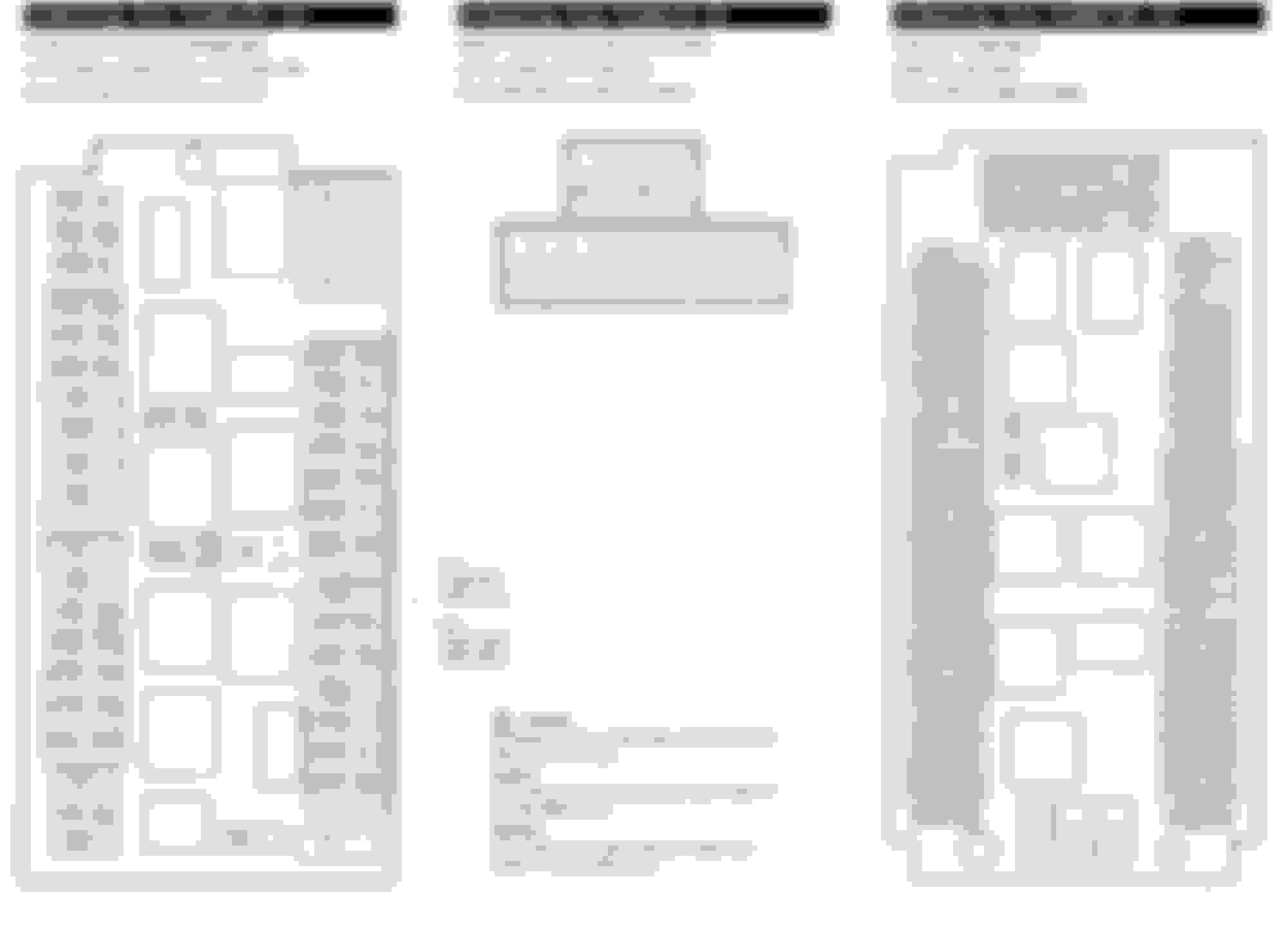
This doc might help. I have mine wired to the same as this and it seems to be working fine.
Though I did get the same fuse taps you did and after an hour of scratching my head and sanding away at the ground point wondering why it wouldnt turn on, I realized that the fuse taps needed two fuses in them to run the power through :\
in one of your pictures, it looks like only 1 of 2 fuses are plugged in? not sure but try putting two fuses in the taps and see what happens
Last edited by NewCents05; 08-18-2018 at 04:20 PM.
This doc might help. I have mine wired to the same as this and it seems to be working fine.
Though I did get the same fuse taps you did and after an hour of scratching my head and sanding away at the ground point wondering why it wouldnt turn on, I realized that the fuse taps needed two fuses in them to run the power through :\
in one of your pictures, it looks like only 1 of 2 fuses are plugged in? not sure but try putting two fuses in the taps and see what happens
Thank you very much. I will take a look. Yes, I took that one picture just showing what I was using. Later I did a proper installation with using 2 fuses in the slots - old fuse for the original circuit and a lower amp for the new one.
Got a Cellink Neo battery. It came with wires prepped for my camera.
So I decided to re-run the wiring to the rear seat. My plan was to seat the battery under the rear seat.
The cable running from the camera to the battery has all three wires - ground, constant, and ignition. It plugs into the battery via a plug.
The battery can be plugged into the cigarette lighter socket or hardwired. I decided to hardwire. The cable has a plug on one side that goes into the battery and on the other it has a stripped wire tip for add-a-circuit connection and a ground round tip.
So I added a add-a-circuit extension, used the same fuses I was using for my ignition-on wire when the camera was hardwired to fuses. And I ran the ground under the carpet to where the foldable rear seat clips in. I removed the cover and placed the ground wire tip under the cover where the cover screw is screwed into metal.
I dont know if that is a good ground point.
The camera seems to work so I go for a test drive. In the middle of the test drive the camera enters Parking Mode and stays in it.
I check the fuses and the 5 amp fuse in the top slot of add-a-circuit extension is burnt out. I turn the camera off via the power button.
I replace the burnt fuse with another 5 amp fuse, but the camera is not turning on anymore. I tried using a 10 amp fuse, some thing. The second 5 amp fuse burnt out too.
The battery is working it seems. Makes the beep when the car starts and 2 beeps when the car is turned off. The light stays on when the car is running.
So thinking that maybe the ground is bad, I disconnect that cable from the battery and use a cigarette lighter cable for the battery. The camera is not turning on.
So I test the camera by using its cigarette lighter cable. Turns on and off as designed.
So the question is what could the problem be if even when I use the cigarette lighter cable for the battery (to eliminate the possibly bad ground) the camera still doesnt get a power through and from the battery after a couple of fuses burnt? Is the wiring I just ran from camera to battery damaged somewhere? Is it the battery?
Take good photo of the Cellink Neo user manual. I can't find it online. I will help you sort out the wiring.
First thing first, which fuse number on the car did you tap power from when using hardwire for the NEO ?
Do not take power from anything but cigarette light socket or its fuse please. This Cellink Neo sucks 5 or 9 amps depending on LOW or HIGH switch setting at input.
I suggest you use only the cigarette socket as power supply for the Cellink Neo , no need hardwire to cigarette socket fuse, unless you want very clean wiring look.
Hardwire :
2nd fuse is the fuse responsible to limit power draw for NEO. 1st fuse is the fuse same as original one to the car before you tap it using that special "tap-a-power-from-ATO fuse" ( you call this ADD-A-CIRCUIT)
IMPORTANT NOTE : To switch the Cellink Neo INPUT side to LOW or HIGH. Minute 7:17 of
LOW is suposedly 5 amps draw ( charging for NEO ) and HIGH is supposedly 9 amps charging for NEO.
I will call Cellink Neo as NEO, so that you wont get it mixed up with the car's battery.
Now here is a big difference by having a NEO in your set up.
01. NEO needs to be charged, hence it could draw 5 or 9 amps from your car's battery or the fuse you tap power from 45 minutes to 1.5 hours. If you draw this much from other than cigarette socket assigned fuse or wiring, you may cause errors to your car electronics if say you tap power from entertainment system or other devices in the car. Your dashcam on its own will not draw more than 1 amp for sure.
02. NEO SHOULD NOT EVER be connected to a constant power, it should be connected to a fuse which is via ACC step 1 ignition. Step 1 turn of ignition key is ACC. Step 2 is crank the engine.
The NEO is the one replacing car's battery duty, so it should never get constant power. NEO is supposed to prevent car's battery drain by itself being the only power supply for your dashcam.
03. How a NEO triggers your dashcam to be in driving or parking mode will probably be this way :
When engine running and alternator is at 13.8 volt or higher, NEO gets charged and will send two positive signals to your dashcam. 1st one is via the Constant and 2nd one is ACC. This becomes driving mode on your dashcam.
When engine is off and car's battery drop to 12.8 volt or lower, NEO sense this condition and send only 1 positive signals to your dashcam, to the constant only. This is the parking mode.
If you have a amperage clamp meter, you can read at what alternator voltage does a NEO starts to draw power ( charge itself ) from the car, to confirm 03 operational logic.
Since I do not have the NEO user manual, I do not know what are the 3 LEDs meaning . The 3 LEDs on top of INPUT sockets.
If you supply power for NEO using cigarette socket , you do not need to run separate ground ( -) as the cigarette socket has + and - 12 volts.
You can buy something like this :
to still allow use of your cigarette socket for say a cellphone charger.
Just remember do not load anything higher than total of 15 amps to the car's cigarette socket. Change that 20 amps fuse you said you use for cigarette sockets back to original 15 amps, it is safer for your wiring from
fuse block to the cigarette socket.
If you want to know how bad or how good a grounding point on the spot you choose, use a digital meter Ohms/resistance feature. 1 meter lead/cable to battery negative post and 1 lead/cable to your chosen grounding spot.
Anything above 0.2 ohms is bad for a ground, for me if in a car* ( *short distance )
Make sure when you do use ohms/resistance feature, do test first the actual lead/cables of the multimeter own's resistance and any extension wire you will use.
You short the two leads of the multimeter and see what ohms reading you get. That is the zero.
What ever other readings you get when testing your grounding spot, deduct the value by the value of the test leads own's resistance.
One more thing. Make sure you fully charged the NEO before you work on it. It surely would have low voltage cut-off to protect its battery and that may lead to dashcam shutting down and you may think your
wiring is at fault. If the NEO uses voltage level to sense the car is in driving mode or parking mode, you probably need 13.8V to 14.3 volt to charge it and can't use direct car battery with engine off which will be 12.9 volt at best.
I have started talking to BlackboxMyCar guys to see if they can help me diagnose the issue.
The battery seems to be charging, but not sending power or allowing power to come through to the camera.
Camera works from the cigarette lighter cable.
I am interested in getting a replacement/test cable that connects the camera to the battery from BlackboxMyCar guys to see if that is the issue. If not, it must be the NEO.
You have digital multimeter right ?
There are 4 pins on the OUTPUT side of NEO
If your NEO comes with its own FEMALE cigarette lighter socket like below to power your camera :
Your camera will not work as designed....... because this connection will only allows 1 of the positive to be available and not both constant and ACC positive.
You need the NEO to output or be configured as below
As I have said before, I started to communicate with BlackboxMyCar people.
Their latest was suggesting that the output cable may be defective or damaged, but they wanted me to try some stuff like moving the fuse in the add-a-circuit extension from top slot to bottom slot.
Since I was using an unused fuse slot in the fuse box there was no reason to do that, plus not having a fuse in the top slot would not send any power to the battery...
Then I moved the fuse back to the top slot of the add-a-circuit, powered the battery back on by setting it to High. Started the car... No change.
Later that night I went back to the car and changed the 10 amp fuse in the add-a-circuit for a 15 amp fuse. Powered the battery back on and set it to High. Started the car... No Change.
Went back to work. Ended my work day. Started the car... No change... Drove home. Turned the car off.
This morning I get into the car and start the engine. Camera turns on. Drove to work. Turned the car off... Camera started parking mode. So far so good.
Magic?
And the battery was charging just fine yesterday on the drive to work, it just wasn't passing any power to the camera. Not even when I swapped the fuse from 10 amp to 15 amp.
If there was a loose connection that got restored during the drive home last night I assume the camera would have turned on instantly as the connection was restored and power sent.
Today the battery is discharging while the camera is in parking mode. So it seems to be working fine.
The question is what changed, and when will it stop working again?
Using the Cellink app I took this screenshot yesterday after swapping the fuse for 15amp, starting and then turning off the car when the camera didn't turn on. Notice the battery says it is Not Used.
This morning, after the camera turned on with ignition and when I got to work and turned the car off... Notice the battery says it is Discharging. There is a continuous fluctuation in output Amps.
Came down to the car about 1 hour later and took another "reading". The output amps is still fluctuating, but since it is discharging I assume the camera is still in parking mode. In the daylight it is difficult to see the light on the camera, and I didn't bring my car keys with me so I couldn't check.
Last edited by ikrinitskiy; 08-21-2018 at 03:13 PM.
Bad contact would be the only suspect if a physical wire is involved and intermittent operation is what's going on and IF without software/algorithm intervention. Its not Magic
Unless NEO uses some sort of minimum load sensing value to decide when to turn itself OFF or ON for its power output. If they have this feature, I sure hope its ON trigger value is as low as 0.05 amps or 0.5 watt.
Some 5 volt USB power bank , like mine, does turn itself OFF when there is no load , or perhaps the minimum load not achieved , and a manual push of ON button will be required to turn it ON again.
Bad contact in a connector set can come from :
01. Poor contact at the insertion point between the female and male copper terminal
02. Poor crimping of the wire to the copper terminal.
03. Broken copper wires within its pvc jacket, if cables are very small diameter.
Below is the OUTPUT pin assignment as what I gather from : http://www.car-dvr.co.uk/cellink_b/p...link_neo6.html
Yellow cable +12V as a constant , that is a car stereo power cable color code, that is a common standard, and probably NEO uses that too. Those 3 cables are indeed tiny/thin, I would not be surprised if you got bad OUTPUT wiring assy.
The Neo Apps is nice, it shows lots of data.
0.2 to 0.1 amps fluctuation of camera power consumption is normal. Usually the higher 0.2 amps is when the video file is being written into memory card.
Single camera F800 claimed mean power consumption of 2.9 watts, that is 0.225 amps at 13 volts.
NEO would probably use some sort of mechanical or solid state relay to jumper/parallel the +12V yellow wire and +12V red wire at OUTPUT, when car alternator is running and produce 13.8V or higher, you then get the Driving mode.
When alternator is not running, that relay wont parallel the 2 positive, only +12 volt at yellow cable has power.... you then get the Parking Mode.
Since surely NEO has low battery protection, it will use some sort of mechanical or solid state relay, to cut off power to your camera at both yellow and red +12V wires
If you can confirm NEO operational logic, you can troubleshoot easier in the future as certain algorithm/software in NEO is/maybe responsible for turning ON or OFF the power output to your camera.
A true physical hardwiring is easy to troubleshoot, but when a software/algorithm is involved and can do ON/OFF intervention, you need to know how they actually work.
I like power-bank product like NEO. I would investigate further for these if I were you :
- At what battery level will NEO cut power to your camera ? Low voltage protection surely exist for Lithium Ion battery as it will not recover when they go too low a voltage.
- At what battery internal temperature will NEO auto shut off for safety reason ? Lit-Ion battery surely has thermal protection. Usually 60 Celcius is absolute max, but NEO could be set at lower temperature.
In hot climate, if your F800 do not auto overheat shutdown first and instead the NEO did, you may think something is wrong with your set up.
- Does NEO has minimum load value for it to turn OFF/ON its power output ? Remember, NEO is just another big power bank with charging capability from a 12V source, it may have power savings feature.
I too have a dashcam, but I bought it for collection of cameras purpose and not for use as dashcam per se. Its a Viofo A119S, its low light Sony starlight sensor is why I bought it.
I also got DDPAI Mini3, but it went dead within 2 minutes of operation ...LOL.
Hope your system work flawlessly for years to come
Thank you very much. I too suspect a bad contact somewhere.
what is weird to me is that if contact was restored during the drive last night I would have expected to see the camera turn on when it got power. That didnt happen.
I got another output cable coming. And 1 half of that cable (battery connector on one end) coming as well. Just in case.
The spliced version of the cable is made from two different cables put together. Basically one that has a connector for the camera and the other has a connector for the battery. The three wires from the other end of each cable are then butt joined (I think) or maybe soldered. It is under heat shrunk insulation tube so I cannot really feel what is inside.
Maybe I will see about testing the cable for continuity while twisting/moving it around some.
hoping it will keep working but I would like to find out for sure why it started working seemingly on it's own so I can control it. Like if bad connection is the problem I would want to eliminate it.
what is weird to me is that if contact was restored during the drive last night I would have expected to see the camera turn on when it got power. That didnt happen.
.
This is why I suspect there could be also software/algorithm intervention, involved in deciding when to supply or not supply power at OUTPUT....this is assuming F800 truly did not get power for its yellow and red cable from NEO.
Software can be a bi-tch
The spliced version of the cable is made from two different cables put together. Basically one that has a connector for the camera and the other has a connector for the battery. The three wires from the other end of each cable are then butt joined (I think) or maybe soldered. It is under heat shrunk insulation tube so I cannot really feel what is inside.
These kind of cables are crimped at the connector, they will never solder as it add cost.
If you check continuity, do shake the cables, pull end to end and "massage" it, sometime it will show where the bad connection are, if any.
This is why I suspect there could be also software/algorithm intervention, involved in deciding when to supply or not supply power at OUTPUT....this is assuming F800 truly did not get power for its yellow and red cable from NEO.
Software can be a bi-tch
It sure can be. I work in software myself.
By the way here is how I have it all connected (but before I switched the 10 amp fuse for the 15 amp). That is an unused slot btw.
These kind of cables are crimped at the connector, they will never solder as it add cost.
If you check continuity, do shake the cables, pull end to end and "massage" it, sometime it will show where the bad connection are, if any.
That is one half.
Here are two halves put together.
It is the very last one on the list of cables for Cellink Power Replacement Cables.
It is the very last one on the list of cables for Cellink Power Replacement Cables.
I see, that is a marriage of F800 hardwire kit and NEO spliced hardwire output assy.
That marriage need soldering for sure and I hope they do a good job. Usually that is the weakest link as only solder bonds both wires type and no more cable jacket providing the extra bond.
With such wire, I usually do small loop and use cable tie. The loop is to make sure any pull on the cable is handled by cable's outer jacket and not the soldering. See my ugly drawing below...
This kind of L shape connector jack often has copper wire breakage inside the casting of the L shape black insulator plastic, bad contact will occur, intermittent operation we get.
The longer the cable of this kind of jack get suspended in air an not tied down, the more overall cable weight get exerted on the black insulator plastic , the sooner cable breakage will occur internally.
One more to look at is this connector locking pin. The red line/color below is the locking pin of the copper terminal ( in green ) to the plastic body of the connector block.
Observe carefully that all 3 copper terminals have the same depth of insertion at the plastic connector body. Sometime the red line/color locking pin does not lock well and the copper terminal moved outwards a bit , causing intermittent contact. More so if we often plug in - plug out this kind of connector.
.
Remember how NOT robust this PC connector below is for high cycle plug in-plug out. I hate this Male Molex connector, their locking pin slips out of place sooner than the female ones. I used to test high power PC fan with this Molex, so the connector get higher mileage than usual.
When I was testing the Volts flowing to the tip of the camera connector I remember only getting a reading on the tip past the ring. Unless I remember incorrectly.
That was when I hardwired to the car fuses and it wouldn't work. Very possible that the cable I was using was damaged.
Hello, I doing this now. And to be honest electronics are not my strong suit. Slow and steady gets it done. I hope.
where did people ground their wiring? I am hoping to use the #15 fuse for the red wire and 21 for the yellow. Does anyone know why there component video plug is there?
Any direction on how to remove the A Pillar cover? I tried prying on it gently, it bends away but is not pulling away from the body. Any thoughts, paranoid about the airbag in this one.
I appears that i am not getting power, no lights or LEDs on the camera, and the wifi does not show a network. There is some weird Chinese network that shows up, but it is not secured and does not stay connected. Reasonably certain that is not the correct one.
Red wire goes to 15, yellow goes to 21.
The hazard lights work fine, when the fuse was not incorrectly i did receive the error message.
Is the ground in the right spot?
any ideas on how to test it? temporarily give it power or otherwise trouble shoot it?


 08-16-2018, 11:03 AM


 I used to test high power PC fan with this Molex, so the connector get higher mileage than usual.