When you click on links to various merchants on this site and make a purchase, this can result in this site earning a commission. Affiliate programs and affiliations include, but are not limited to, the eBay Partner Network.
Hi there,
I've browsed lots of posts here over the years but never posted or made an account. Recently i was getting ready to install an aftermarket hitch on my 2015 GLK and i noticed there wasn't a good write up on how to connect it, so i decided to write one. If its redundant feel free to let me know and i can delete it, but i couldn't find one.
Background about me.. I went to college for electrical engineering, spent a few years working at a shop installing aftermarket electronics and remote starters into vehicles, worked as an electrician for the railroad for a number of years.
This is not to be a definitive guide, vehicles / packages / harnesses may vary and you are responsible for testing and verifying anything that you do to your own vehicle.
Lets begin. I have a 2015 GLK 350 without the factory towing package. It has the appearance package and the LED taillights. I was interested in personally adding a hitch and trailer harness to tow as it didnt come with it from the factory and the dealer i purchased it from wanted to send it to uhaul
Products chosen:
I bought the DrawTite hitch 75774 and the Curt Universal Protective Harness 56236. This is not an endorsement of these products, just what i chose to use. I picked the hitch because it didnt require dropping the exhaust like the Curt and is rated for higher tongue capacity. I picked the harness because of its availability. For my 2015 I needed a "protective" harness that supports 2 wire setups. Instructions for a "2 wire" setup
My 2015 has tail lights that are LED and a separate LEd strip on each side that is shared with the blinker and brake lights. That makes it a 2 wire
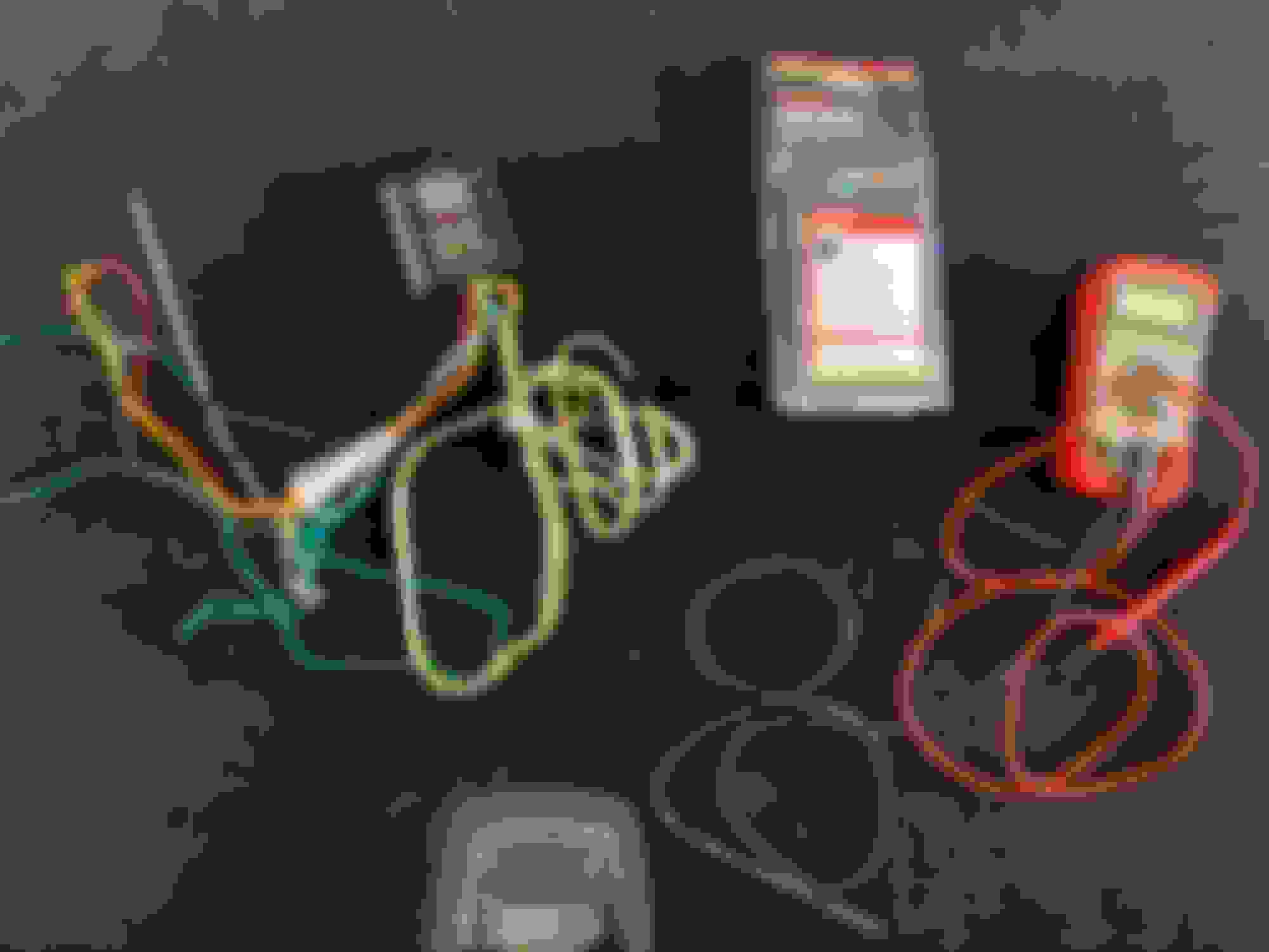
Tools / supplies needed:
Multimeter - to identify / verify wires
T30 Torx - to remove rear trim panel
T40 Torx - to remove trunk floor battery cover
1/4 ratchet, 6" extension, 10mm socket - to remove the battery cover, ground bolts, etc
Pliers or crimpers
an inline fuse holder for power
Optional:
I hate the vampire clips that the kits include. So i used a tap method with spring assisted strippers and a roll of electrical tape. Im a car i only use 3M Super 33, its just way better than anything else.
Disassembly:
Start by removing the fake floor by using the handle
In front of the metal latch is a T30 torx, remove that
The trim panel can then be removed by pulling up on it. Its secured with 4 clips, you want to be gentle but firm.
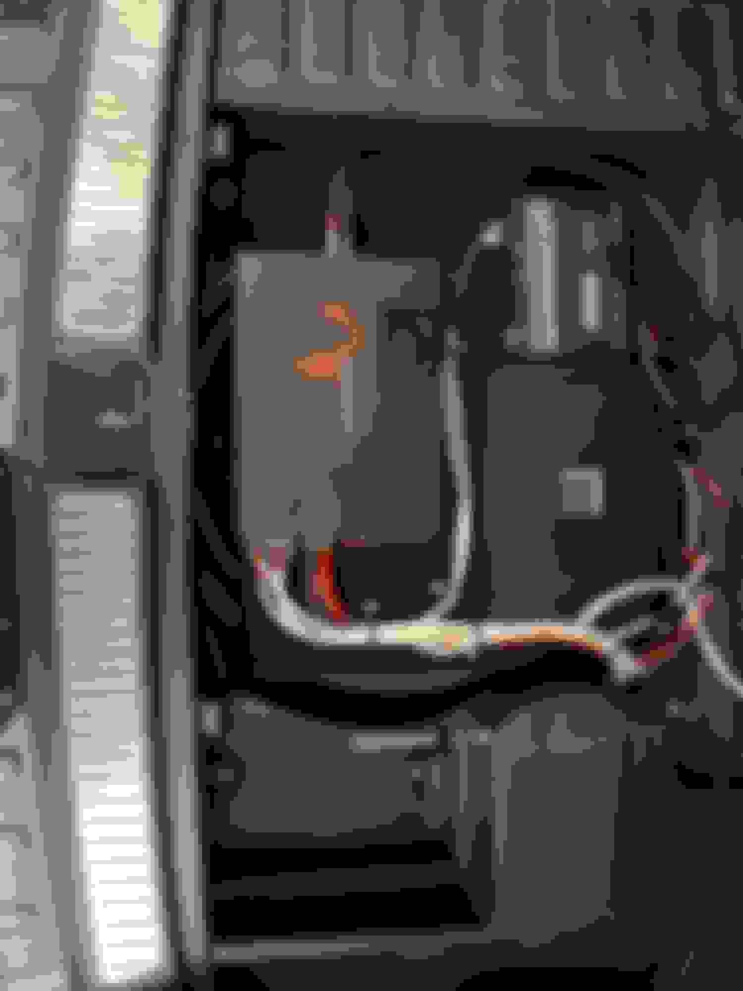
Next we are going to remove the battery cover on the right. There is a rubber cover in the right compartment that you can lift up to expose screws underneath. Remove 2 T40 and 2 10mm, then lift up on the plastic cover.
Here is whats below that cover, minus the 2 red cables on the right which are for my amplifiers.
Remove the covers to Expose the backs of the lights, there is an access panel on each side with a little quarter turn knob.
You can see the harness in the back of the tail light, this is what you will be connecting to.
The harness installation is straight forward and needs the following:
Black - goes to Battery positive
White - goes to vehicle ground
Red - goes to vehicle ground because we are connecting to a 2 wire system
Yellow - goes to driver side Brake/Turn
Brown - goes to the tail lights (parking lights)
Green - goes to the right turn/brake
Thinking through our installation:
the power can be found on the passenger side at the battery,
the ground is available on both sides,
the tail is on both sides,
the passenger side brake/turn is on the passenger side,
the driver side brake/turn is available on the driver side, however its fed from the passenger side and goes across the rear of the vehicle behind the spare.
Based on this i decided to put my box and all of my connections in the passenger side.
Because i didnt want to drill the vehicle i opted to leave the harness inside and store it in the passenger side compartment.
I prepped my harness for the wiring locations, this part is preference, its just how i do it.
so everything is separated by location.
Black white and red are all going to power/ ground
yellow to the driver side wiring harness
green brown to the passenger side
Next i tested my lights. on my vehicle i found the following
passenger side:
Grey/Blue (pin 3) Tail Lights - this went from about 300mv at rest to 12v when on
Blue - Brake/Turn - this went from 2v at rest to 12v when on
driver side
Pink - Brake/turn - this went from 2v at rest to 12v when on
Time to start making connections.
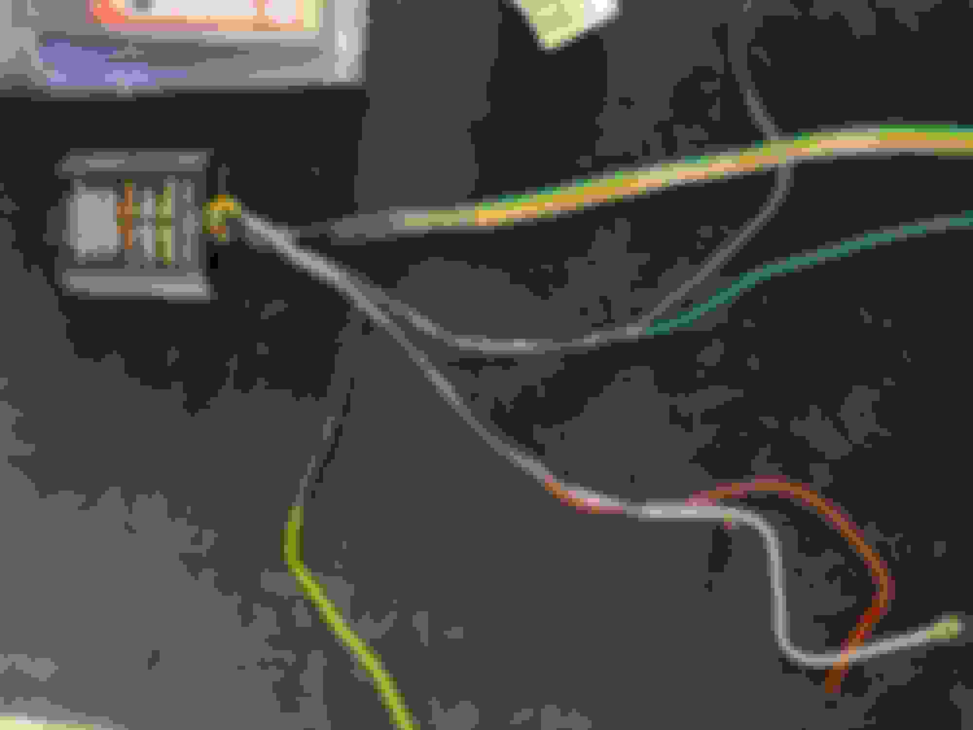
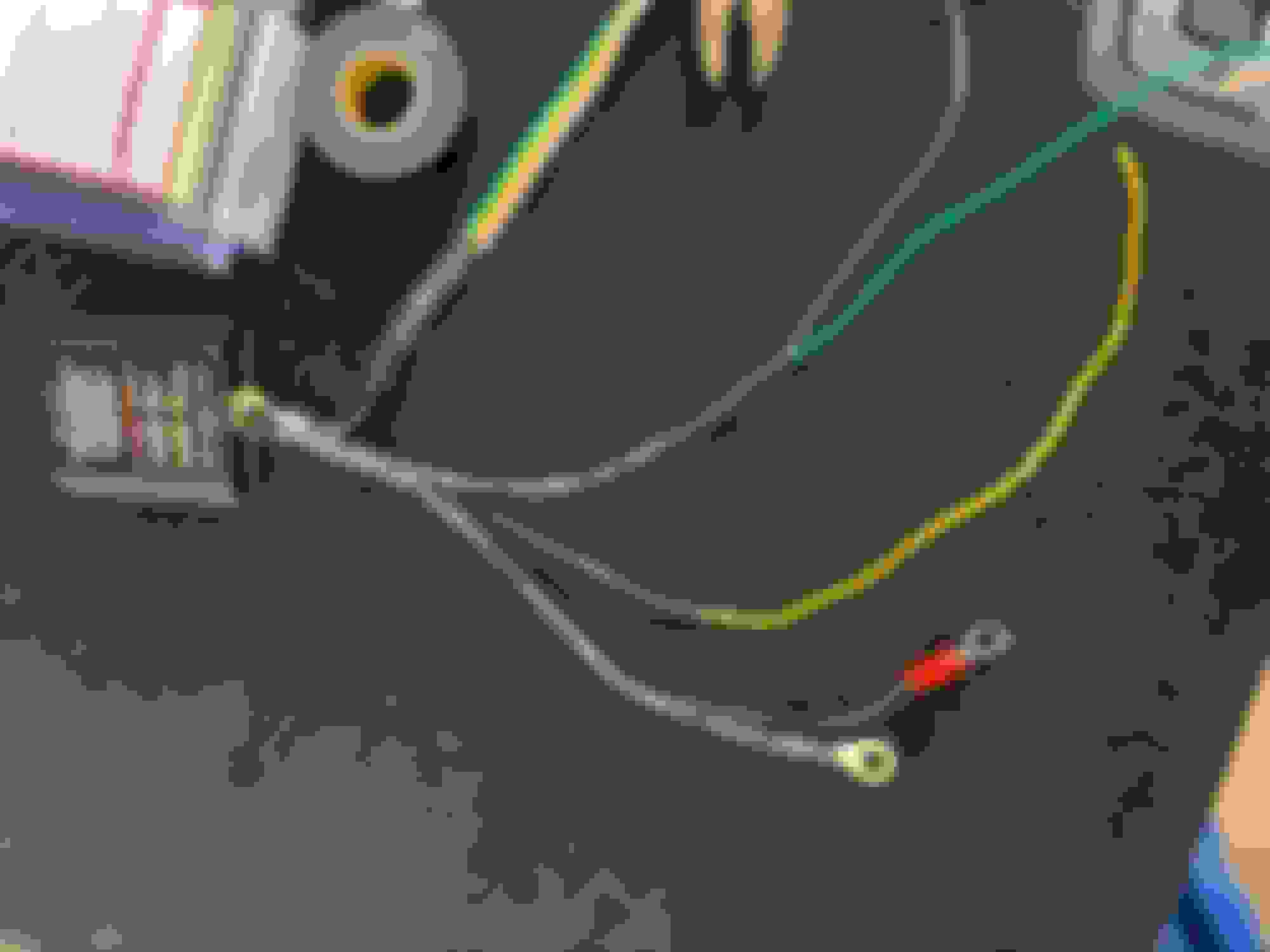
Start with ground, there is a nice one in the passenger side compartment. its the group of brown wires. 10MM nut
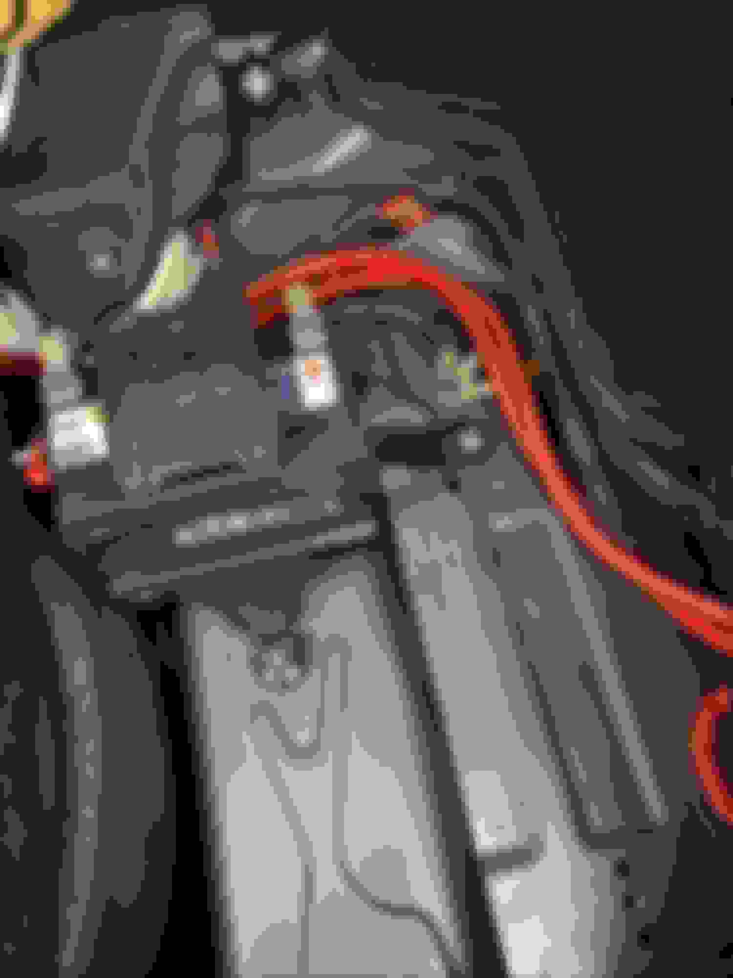
Next we want to connect power
I got my power from the battery isolator mounted under the panel. This device connects the hood battery and the rear battery when the vehicle is on and disconnects them when its not. Its a great source of power. You need to put a fuse here to protect the battery from a short. i used an existing fuse holder i had my amplifiers wired into.
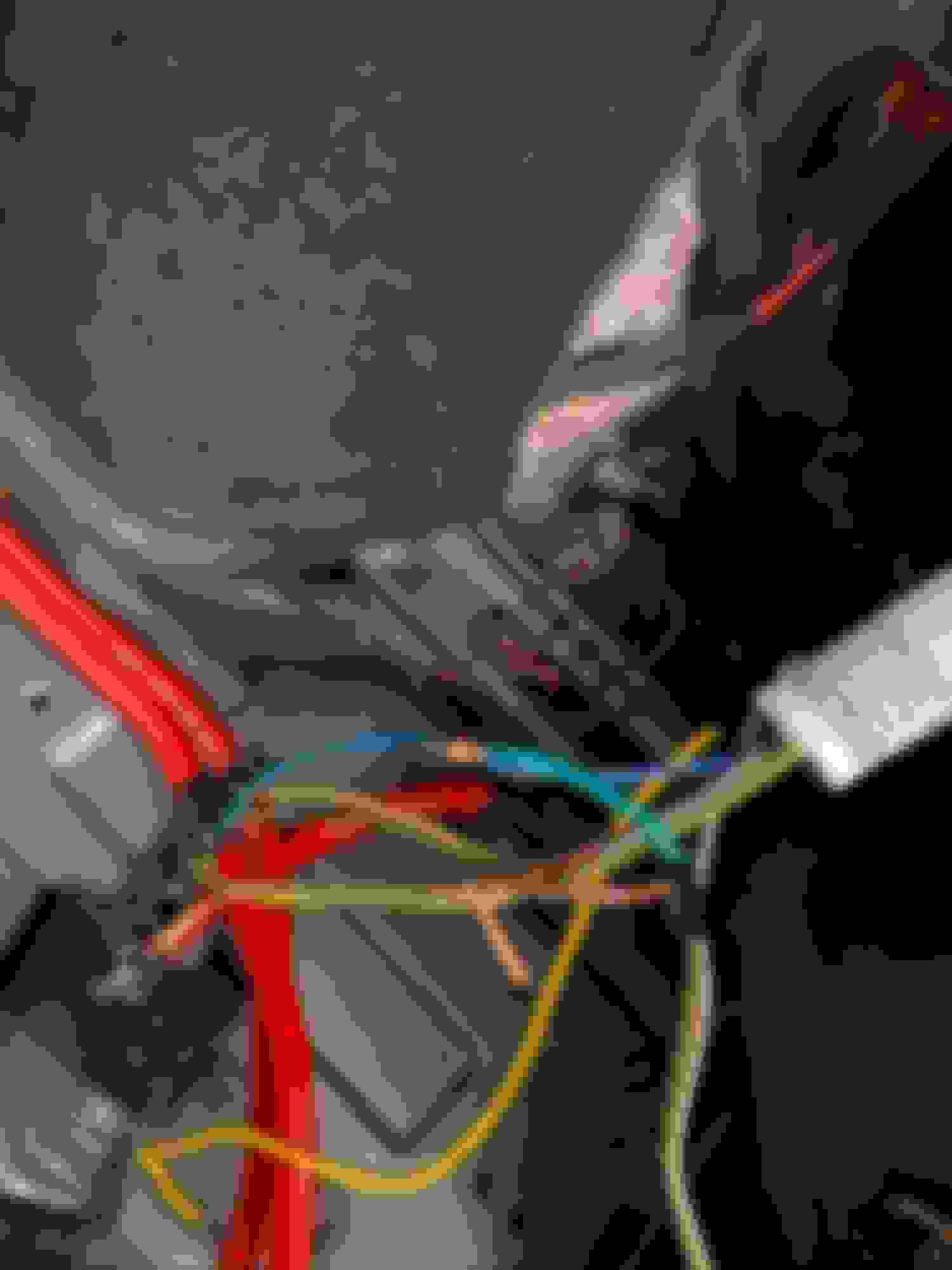
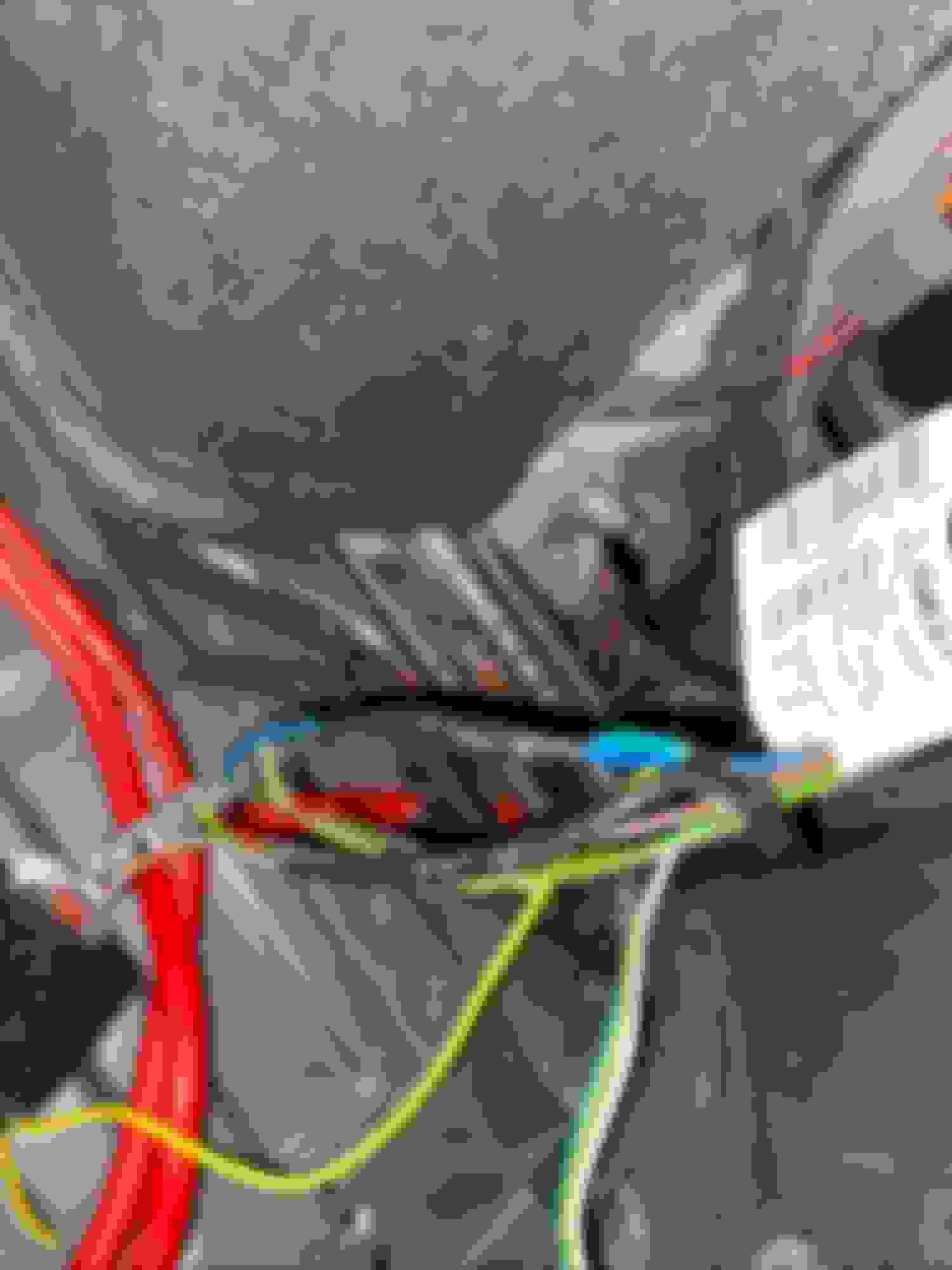
now we can make our connections behind the passenger tail light. This has always been my method to connect to an existing harness, strip the insulator off the wire in the middle, poke something sharp through the center of the copper strands, then poke the wire through and wrap it around. THis makes a secure connection that with a little practice can be clean and reliable.
connect the brown on the trailer to the grey/blue on the tail light
connect the green on the trailier to the blue at the tail light.
Tape up the harness and plug it back in
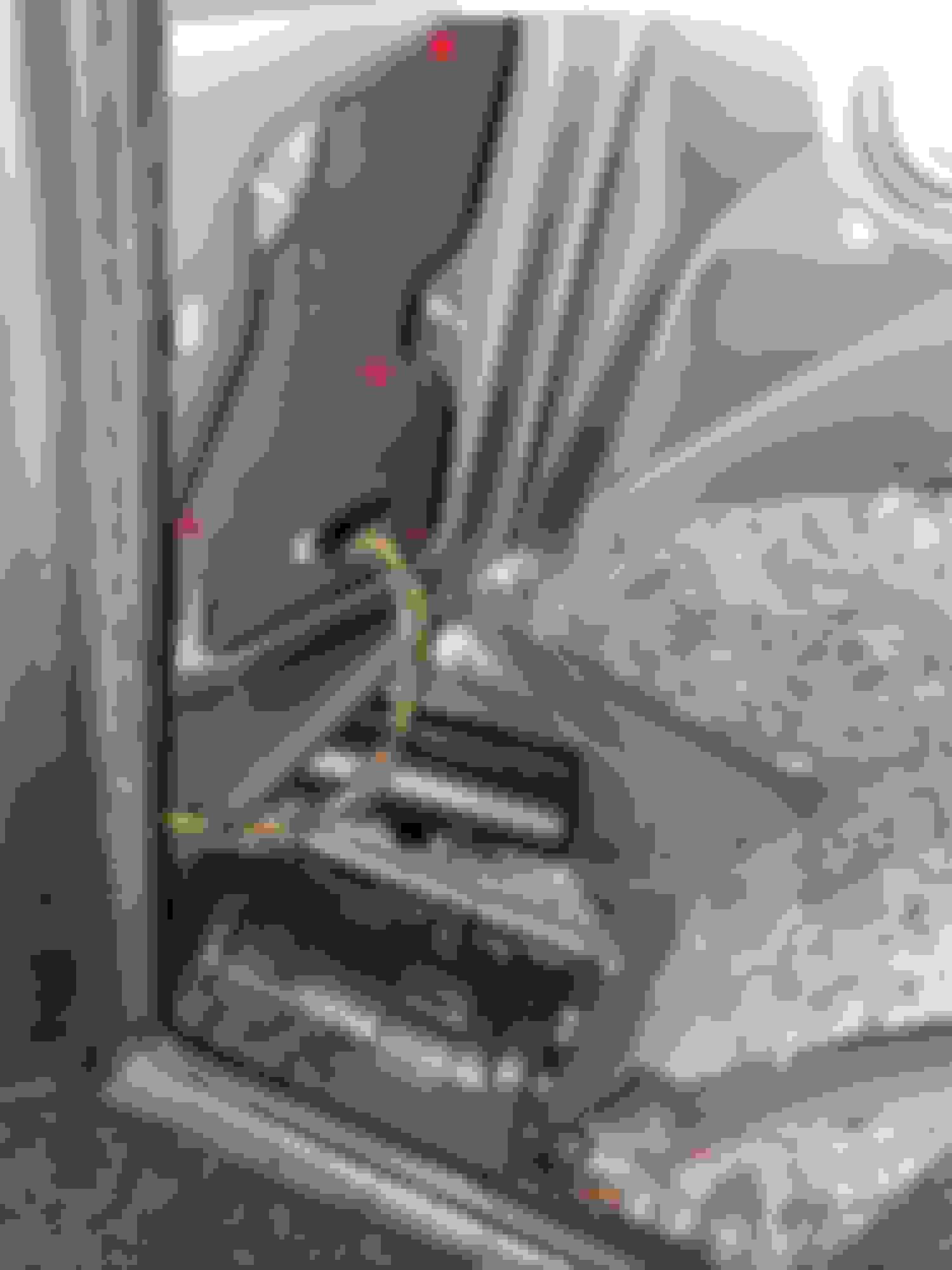
next you can grab the pink wire for the driver stop/turn in the harness at the bottom of the trim. Connect the yellow trailer to that.
tape the harness up when youre done
At this point everything is connected. Verify you plugged the harnesses into your tail lights and test your work.
the trailer harness has 4 pins.
The white is ground, the white and brown should show 12 volts when your tail lights are on and 0 when they are off
the white and yellow should show 12v when the brake is depressed and intermittently when the left turn signal is on
the white and green will match the above but for the right turn
If everything looks good, you can button it up. I rolled up the harness in the right side compartment which is where it will stay until i need it. I used double sided tape to secure the little black box behind the tail light in the passenger side compartment.
Some important notes:
Make sure you route the cables that leave the compartment under the plastic so the door can go back on
Make sure you test your raw wires and your finished product
Make sure that you connect Ground First and then Power. This keeps the harness from making the BCM freak out when the signal wires are connected
Make sure you use a harness with protection (has its own power and ground) or you will fault the lights when the trailer lights are connected to the car.

 07-12-2020, 02:33 AM