When you click on links to various merchants on this site and make a purchase, this can result in this site earning a commission. Affiliate programs and affiliations include, but are not limited to, the eBay Partner Network.
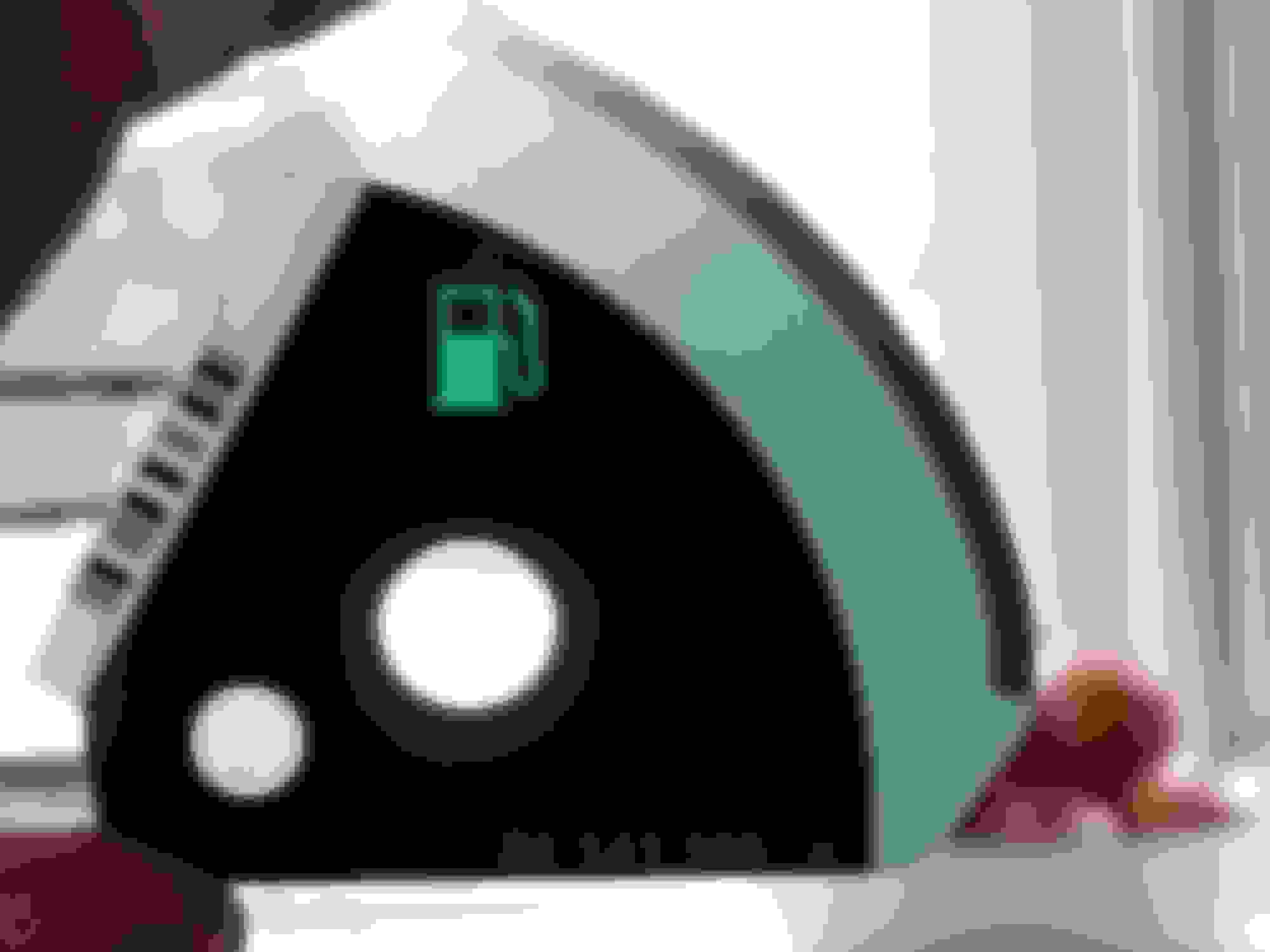
A minor annoyance: the MFD LCDs dim too much at times. I have to remove my sunglasses to read them. I've noticed that if the sun angle is right, light reflecting off the back of my right hand on the steering wheel causes the display to brighten up. So, I decided to find the photosensor and see if I could change the dimming function. I found it hiding behind the translucent circle in the lower left corner of the fuel gauge:
With the cluster out of the car (no power), and full brightness (flashlight right on it), the resistance across the sensor is 1000 ohms. At full darkness (finger covering it), 150,000 ohms.
With the cluster in the car and powered on, full brightness = 0.1V across the sensor. Full dark = 4.75V.
I want to reduce the dimming toward the dark end of the range, so I soldered a 500,000 ohm resistor between the bottom 2 connections of the ribbon cable that connects the gas gauge PCB to the main PCB. Result? Essentially no dimming at all. I ran wires out from the connection points to the cavity where the reset stalk resides, so I can change the resistor without taking the cluster completely apart. I'll run it this way for now. If, this winter, I find the LCDs to be too bright after sunset, I'll try a 1 meg-ohm resistor,
There is another thread on disassembling the cluster, so cliff notes here:
1, Lower the steering wheel
2. pull the shade back to remove
3. remove 3 torx screws (the bottom center one is recessed pretty far).
4. pull out cluster
5. disconnect the electrical cable
6. pry 7 tabs open (barely) enough to remove the lens assembly
7. pry out the retainers (barely enough) and free the PCB assemblies from the white plastic back shell
8. tilt the gas gauge PCB away from the main PCB to expose the ribbon cable solder joints.
There is no need to remove the gas gauge pointer, bezel, etc to get to the ribbon cable solder joints.
a SMD resistor will fit right between the ribbon cable pins. I'd suggest starting at 1 megohm to 1.5 megohm if you want to still have some dimming, but I haven't found the exact right value.
 09-21-2019, 11:34 PM