


••• Project Stock to Awe •••

Banned
Joined: May 2004
Posts: 3,797
Likes: 2
From: Richmond Hill, Ontario
2003 E55 AMG
That's in effect what the SLR style coolers do.. They combine the air-water intercooler w/ the surge tank.. When you install these intercoolers, your surge tanks come off..
Banned
Joined: May 2004
Posts: 3,797
Likes: 2
From: Richmond Hill, Ontario
2003 E55 AMG
You are asking all the right questions Steve!!! 
There is absolutely no point in doing SLR style intercoolers if you leave the IAT sensor at the back of the engine in the stock location because it will just measure pre-cooling, the ECU will see the high temp and pull timing.
On the SLR engine shot from the back, if you look at the pic I posted courtesy of Siswati, you'll see 1 plug ontop of each tank at a 45deg angle just before the air stream goes downward.. The SLR uses 2 IAT sensors from what I understand.. This is a safety measure to ensure that 1 side doesnt fail.. Remember, SLR uses 2 pumps, 2 reservoirs, etc.. they treat each half of the engine separately.
One of the engineering challenges is going to be how to adapt that to our single input on the ECU wire loom. We either have to plug 1 side and just read from the other, or get the SLR pinouts for the ECU and compare against our wire loom and see if there is a way to adapt it.
I am looking into the ECU wiring now...
MBWorld Fanatic!


Joined: Jul 2005
Posts: 3,174
Likes: 19
From: London, UK
No longer stock '06 E55, A3 3.2 Quattro, GLE 400d, R107 280SL, Golf Polo
I have to say been thinking about this all weekend ... (I know its pretty sad)... but if I look at that open I/C and that open end of the exhaust header - I cannot help but feel a turbo and some pumbling here would fit in very well here ... 

Thread Starter
Super Member


Joined: May 2006
Posts: 566
Likes: 21
From: Australia
03 E55 AMG
Finny and Vrus - thanks for your exceptional contributions to this board, but also for the way in which you so generously share your trials and tribulations ...... all of us mere mortls here are so much wiser about our cars because of your exploits.
Would absolutely love to sit down with you guys someday and shoot the breeze - drinks are on me!
Would absolutely love to sit down with you guys someday and shoot the breeze - drinks are on me!
Florida hey? isn't that where the biggest engines in the world are launched into space? I must watch a launch one day, I'll look you up when I'm in the area. I'm going to check out all the space stuff when I'm up there next as well.

One of the engineering challenges is going to be how to adapt that to our single input on the ECU wire loom. We either have to plug 1 side and just read from the other, or get the SLR pinouts for the ECU and compare against our wire loom and see if there is a way to adapt it.
I am looking into the ECU wiring now...
I am looking into the ECU wiring now...


MBWorld Fanatic!
Joined: Jan 2002
Posts: 1,130
Likes: 36
From: Carefree az usa
2020 S560,14 ml350, 03 sl55, silver, pano, slr cams, evo headers, lsd, 2019 s63 cab.
autoweek mag has a article about the new volkwagen small suv. they are offering a twincharger, S/C and Turbo engine. something like only 190 hp but it will be interesting to see how it is designed.
MB World Stories
The Best of Mercedes & AMG

Manual Mercedes? 6 Times Sindelfingen Let Drivers Have All The Fun
Verdad Gallardo
Mercedes SLR McLaren 722 S Is Extremely Rare Example Modified by McLaren
Verdad Gallardo
8 Classic Boxy Mercedes Designs That Have Aged Like Fine Wine
Verdad Gallardo
Flawlessly Restored Mercedes 190E Evo II Heads to Auction
Verdad Gallardo
Electric Mercedes C-Class Unveiled: 11 Things You Need to Know
Verdad Gallardo
Mercedes EQS Gets A Major Update: Everything You Need to Know
Verdad Gallardo
5 Underrated Mercedes-Benz Models That Don't Get the Love They Deserve
Verdad Gallardo
Mercedes 300D Has Pushed Well Past 1 Million Miles and It Ain't Stopping
Verdad Gallardo
10 Most Reliable Mercedes-Benz Models You Can Buy Used
Verdad Gallardo
Almost a Member!
Joined: May 2007
Posts: 25
Likes: 0
If it was how they planned on doing it when they were speculating the twin charging, I believe it was charger feeds the turbo for off idle power. When turbo reaches boost, charger is bypassed with an electronic actuator valve.
MBWorld Fanatic!
Joined: Jul 2005
Posts: 3,174
Likes: 19
From: London, UK
No longer stock '06 E55, A3 3.2 Quattro, GLE 400d, R107 280SL, Golf Polo
Problem with the S/C is how do you get it to disengage smoothly ... easy to get the clutch to disengage. Two things are difficult to control - the boost blending and the energy drop/gain when the s/c engages/disengages ... aint easy in my book...!
For an efficient setup charger needs to shut down otherwise it just saps power.
For an efficient setup charger needs to shut down otherwise it just saps power.
Thread Starter
Super Member
Joined: May 2006
Posts: 566
Likes: 21
From: Australia
03 E55 AMG
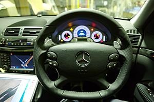
Remember that fine looking steering wheel from Ebay that I last posted up... Well it doesn't fit an 03 version so I did some exploratory poking around and found a simple solution. For any one who can use a soldering iron I strongly suggest having a go at this mod or get a mate with some basic electronics skills to help you out... "however" I will warn that these air bag devices "WILL" take your head off in a split second! Static electricity can detonate the charge and put you in a box 6ft under so don't *** with it unless you know what your doing!!!... and most importantly keep it away from kids!
The photos are a rough guide on how it was all done. So go have some fun!
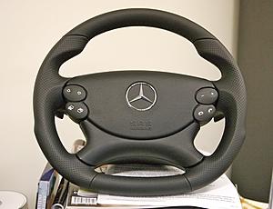
The organ to be transplanted... I ordered this with the Buttons and an Airbag as extras.
Link: http://cgi.ebay.com/ebaymotors/ws/eB...m=320122093493
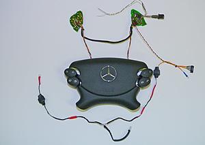
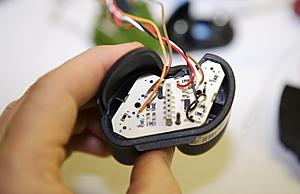
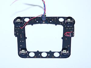
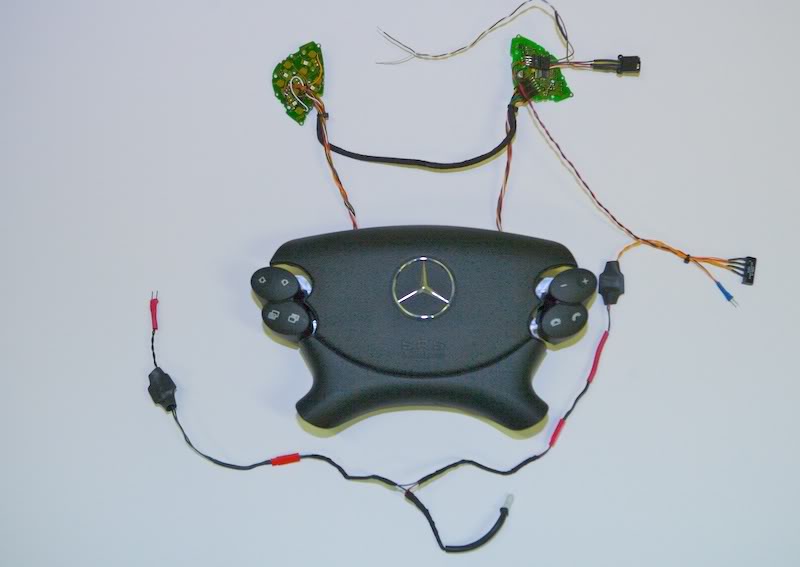
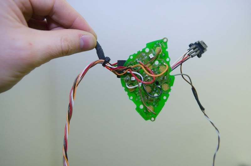
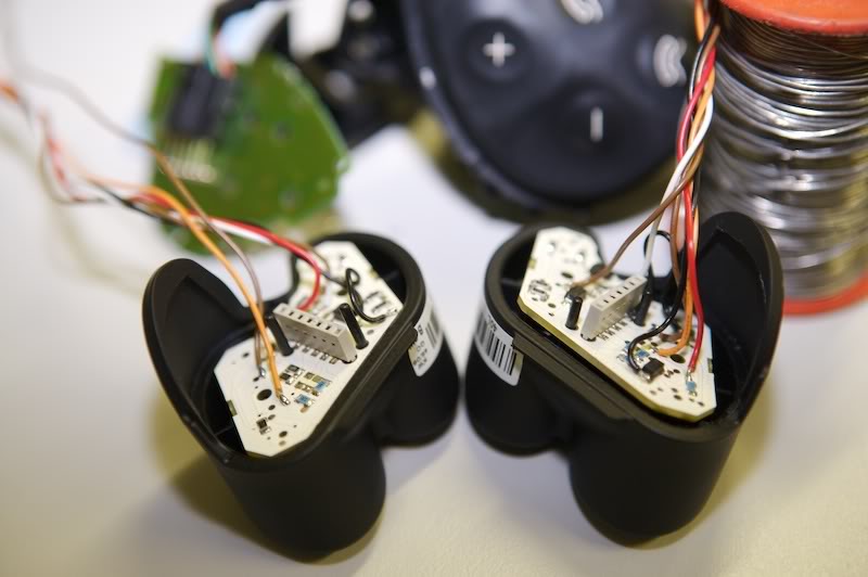
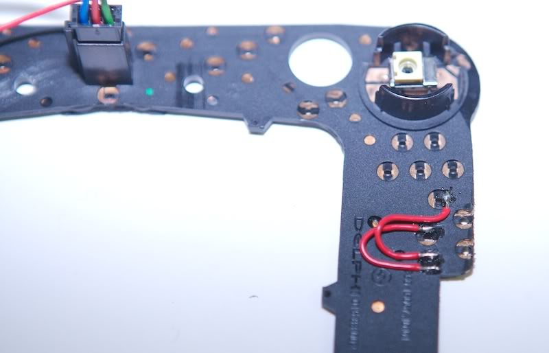
There were two problems, the paddles didn't work and the supplied interface didn't work either. So without altering the stock electronics I just piggy backed the new stuff on to the old stuff. The upper PCB's are the controllers for the horn and buttons and the lower cables are fore the gear paddles. To the right you'll notice a small black relay added to the right paddle because the stock switch is normally closed and the new one is normally open, so I taped 12 vdc from the stock interface serial bus line to power the relay... problem solved. The night LED's on the buttons and the buttons as well share a switch common and power bus common which minimizes wiring. (1) common (2) LED power (3) SW1 (4) SW2 (5) SW3 (6) SW4... The free wire hanging off is for the horn.
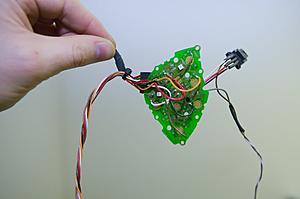
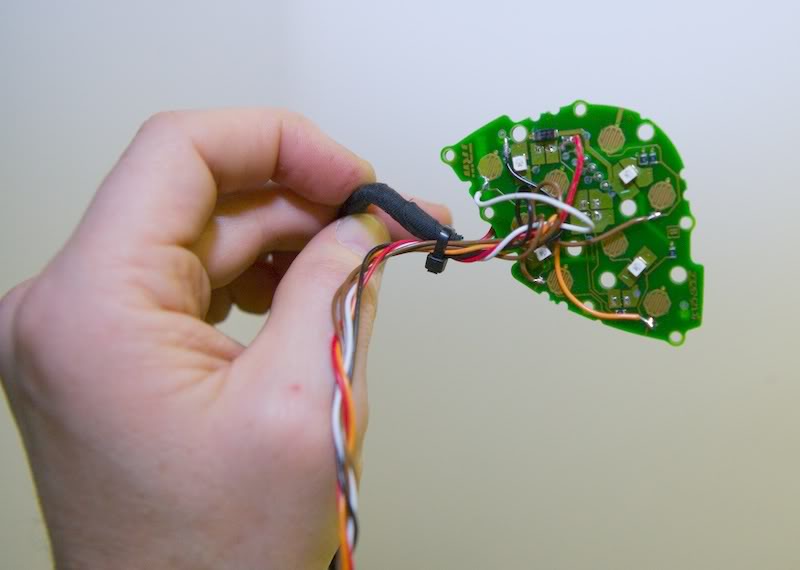
This is the piggybacked stock master board with the horn wire hanging off. The bus plug was removed from off the horn switch board.
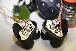
The slave piggybacked switch board. I also removed the resistors for the LED's so there would be no current drop to the transplanted new ones to maintain optimum brightness.

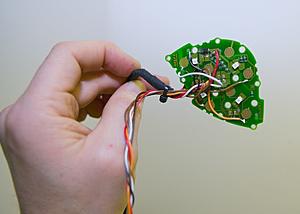
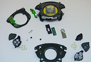
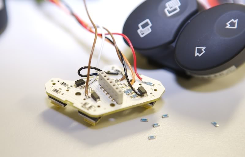
Taped donor board. The surface mount resistors were removed from the switch circuits. The common and LED circuit was left intact.
Other side... same work here.
Ready to go for testing with the meter and a 12v source.
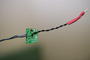
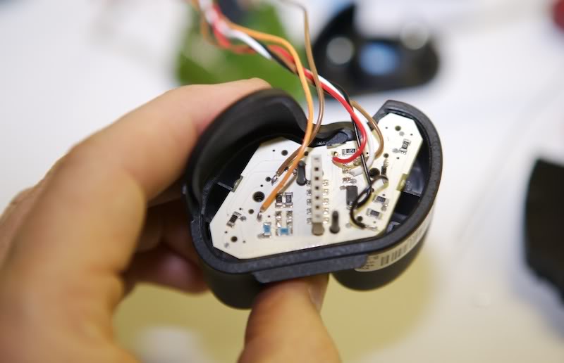
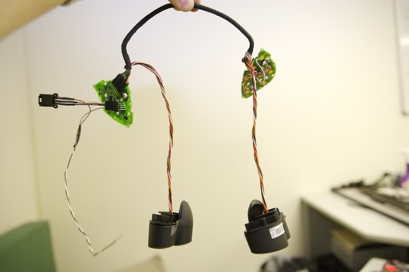
Piggybacked left paddle board which required no mods because it used a N.O switch which was the same as the new one.
Completed button interfaces.
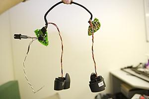
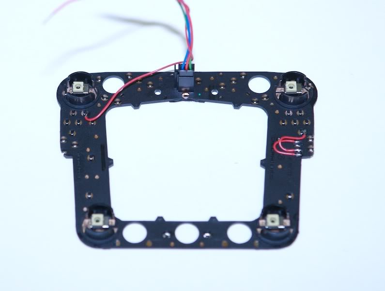
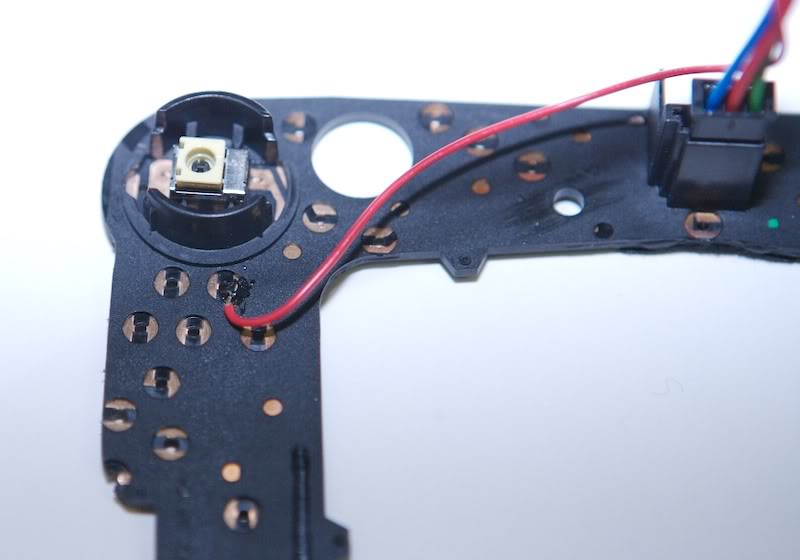
The new horn switch assembly. This had two sockets on the let and right which plugged into the original switch packs. These were considered useless and chopped off. I then added these little red links to link up all the horn switches which will be connected to the stock interface.

Added horn switch common.
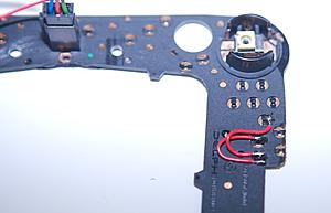
Links for switched side.
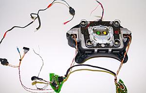
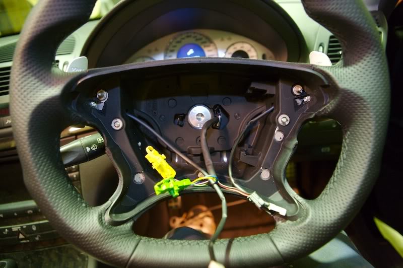
Ready for installation...
There's so much space in here that you could swing a dead cat.

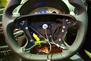
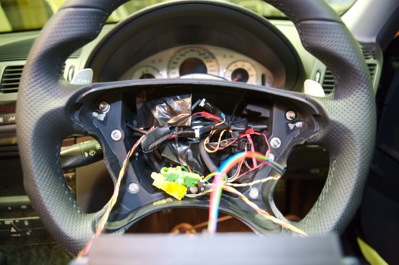
The dogs breakfast all stuffed in. I used some Gaffer tape to cover the stock electronics and a little to hold the paddle plugs together.
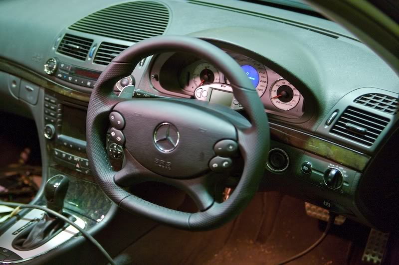
Ran a diagnostic with STAR which confirmed all was well.
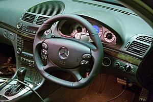
Looks cool hey
All the crap left over. Make sure the old Air Bag is stored or disposed of correctly.
Cheers...
More latter.
The photos are a rough guide on how it was all done. So go have some fun!

The organ to be transplanted... I ordered this with the Buttons and an Airbag as extras.
Link: http://cgi.ebay.com/ebaymotors/ws/eB...m=320122093493
There were two problems, the paddles didn't work and the supplied interface didn't work either. So without altering the stock electronics I just piggy backed the new stuff on to the old stuff. The upper PCB's are the controllers for the horn and buttons and the lower cables are fore the gear paddles. To the right you'll notice a small black relay added to the right paddle because the stock switch is normally closed and the new one is normally open, so I taped 12 vdc from the stock interface serial bus line to power the relay... problem solved. The night LED's on the buttons and the buttons as well share a switch common and power bus common which minimizes wiring. (1) common (2) LED power (3) SW1 (4) SW2 (5) SW3 (6) SW4... The free wire hanging off is for the horn.
This is the piggybacked stock master board with the horn wire hanging off. The bus plug was removed from off the horn switch board.
The slave piggybacked switch board. I also removed the resistors for the LED's so there would be no current drop to the transplanted new ones to maintain optimum brightness.
Taped donor board. The surface mount resistors were removed from the switch circuits. The common and LED circuit was left intact.
Other side... same work here.
Ready to go for testing with the meter and a 12v source.

Piggybacked left paddle board which required no mods because it used a N.O switch which was the same as the new one.
Completed button interfaces.
The new horn switch assembly. This had two sockets on the let and right which plugged into the original switch packs. These were considered useless and chopped off. I then added these little red links to link up all the horn switches which will be connected to the stock interface.
Added horn switch common.
Links for switched side.

Ready for installation...
There's so much space in here that you could swing a dead cat.
The dogs breakfast all stuffed in. I used some Gaffer tape to cover the stock electronics and a little to hold the paddle plugs together.

Ran a diagnostic with STAR which confirmed all was well.
Looks cool hey

All the crap left over. Make sure the old Air Bag is stored or disposed of correctly.
Cheers...
More latter.
Last edited by Finny; Jun 26, 2007 at 12:23 PM.


Senior Member
Joined: Jul 2006
Posts: 259
Likes: 0
From: SF Bay Area
06 E55 SOLD, 89 300 SE 375,000 miles

Um.........Finny.
You put the steering back on the WRONG SIDE of the car!!!!!!!!!!!!!!!!!!!!!

Buddy I am simply amazed at your skill level and tenacity.

You are my hero
Daryoosh

MBWorld Fanatic!
Joined: May 2006
Posts: 3,042
Likes: 0
From: So.Ca.
E55
Any idea of when you'll have it up and running?
Im very curious about the TB bypass and your meter that you have hooked up to it.Ive always wondered if the ecu is bleeding boost off and or when it is.
Im very curious about the TB bypass and your meter that you have hooked up to it.Ive always wondered if the ecu is bleeding boost off and or when it is.
MBWorld Fanatic!
Joined: Oct 2006
Posts: 3,642
Likes: 13
From: Caribbean/Florida/Colorado
E-ZGO 53hp., 1999 E 430 sport, 2004 E 55, 2008 Tahoe LTZ on 24"s
Finny we are jones-in
Been over two weeks, he is out running tests on that beast I just know it.
Thread Starter
Super Member
Joined: May 2006
Posts: 566
Likes: 21
From: Australia
03 E55 AMG
Found some interesting info on the bypass valve. Apparently it's used for fuel economy reasons only. It reacts to load and adjusts accordingly. So in theory having the pedal to the metal should result in the valve being fully shut
We'll see soon...
MBWorld Fanatic!
Joined: Jan 2002
Posts: 1,130
Likes: 36
From: Carefree az usa
2020 S560,14 ml350, 03 sl55, silver, pano, slr cams, evo headers, lsd, 2019 s63 cab.
it has gotten to the point that you, Finny, must give up sleeping. we all need more info faster. keep it up. what do you say about stuggart tech post on vrp belt pulley sytem?


