Mercedes-Benz E-Class AMG: How to Install Coilovers
Replacing your stock suspension with coilovers not only looks good, but improves performance. It's just the thing to turn that world class Mercedes-Benz E-Class sedan into a world class sports car.
This article applies to the Mercedes-Benz E-Class AMG (2002-2009).
The luxurious suspension of the Mercedes-Benz E-Class is second to none. If you are like many owners looking to turn that luxury into a sportier force to be reckoned with, a coilover suspension is for you. A fully integrated adjustable coilover system allows you to adjust the ride height to not only give you that low ride of your dreams, but will make your car nimble. Don't let such an undertaking scare you into dropping a large amount of cash in the pockets of a professional. You can do this job yourself in your own garage.

Materials Needed
- Hydraulic floor jack
- Jack stands
- Breaker bar for lugs
- Ratchet with extensions, socket set with deep well sockets
- Flat head screwdriver
Step 1 – Raise the front end
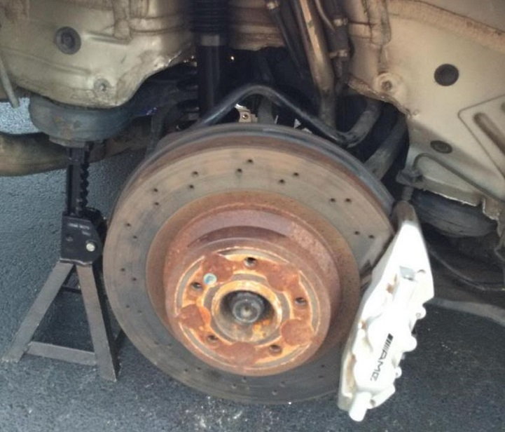
Break the lugs free on the front wheels, loosen but don't remove them. Use a hydraulic floor jack and lift the front end of your car at the recommended jacking location. Place on jack stands at the recommend jack stand locations as well. Chock the rear wheels to prevent rolling. Remove the lug nuts and remove the wheels.
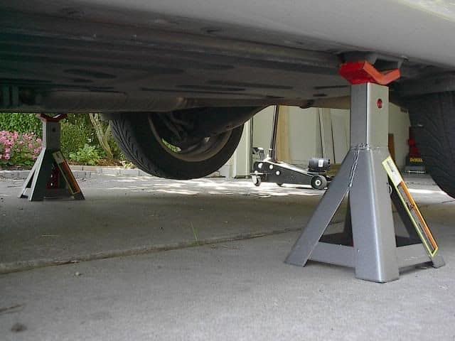
Pro Tip
Never work under a car without using jack stands on level ground. Using just the hydraulic floor jack is not safe.
(Related Article: How to Jack up Your Car.-MBWorld.org)
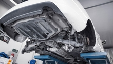
Step 2 – Remove fender liners and undertray
Use a nut driver to remove the several nuts holing the undertray and fender liner in place over the tire in the wheel well. Set these aside and be cautious to not lose any nuts.
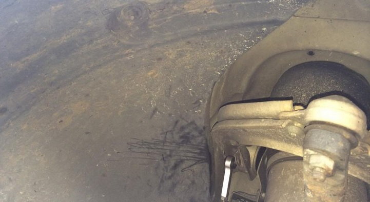
Step 3 – Remove ride height suspension sensors
There are four ride height sensors; one on each end link. They are attached using quick disconnect wiring harnesses. Disconnect the wiring harness and follow the wires to the frame rail. Then pop the clip that holds it there. Trace the wire that runs from the shock to the large harness distro. Pull just this lone wire and its piece of the harness. Leave all the others intact.
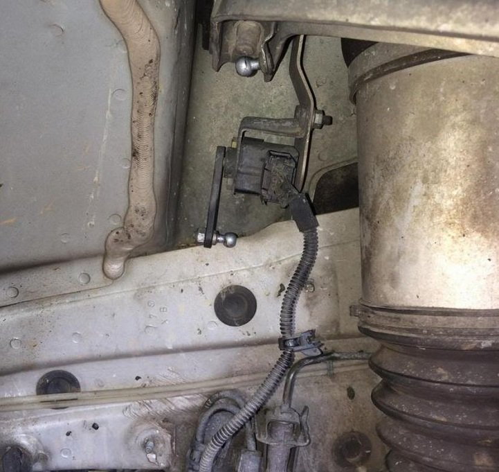
Figure 3. Remove the quick disconnect wiring harness and pull the ride height sensor. 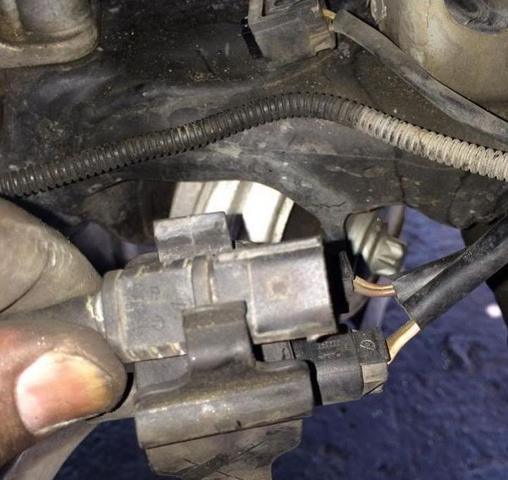
Figure 4. Trace the wires back to this harness distro. Remove the one plug for the ride height sensor.
Step 4 – Remove the air-ride compressor (optional)
When you follow the cable from the large wiring harness distro to the sensor, you'll end up at the air compressor. It is completely up to you whether or not you wish to remove this behemoth. If you think you'll want to put the car back to stock, you should leave it. Otherwise, simply remove the three bolts at the bottom and it will come right out. Disconnect the wiring harness for the compressor and cover it with black electrical tape. Clip the lines going to the distro block and cap with vacuum plugs and leave them alone.
Step 5 – Remove the lower mounting bolt
Remove the lower shock mounting bolt with a ratchet and 21 mm socket. Pull the shock up off the lower control arm.
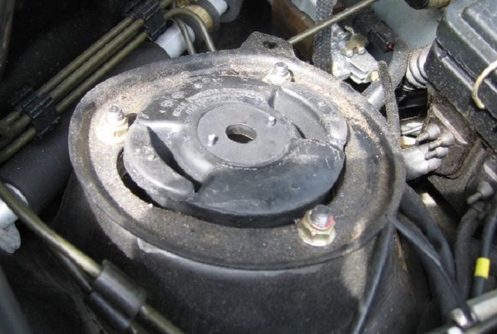
Step 6 – Remove the three upper mounting bolts from the shock tower
Use a ratchet and a 17 mm socket to remove the three mounting bolts. Be careful that you don't let the shock assembly come crashing through the wheel well. It would be useful to engage a second person to help with this part. Otherwise, when the shock assembly drops, it may take a little turning and twisting to pull it out from the well. Set it aside carefully. Using a complete coilover kit alleviates the need to use a spring compressor on the old shock to remove the upper mount, and re-use it. The entire kit is basically bolt on and has all your needs. You will also want to take this time to undo the clip in the engine bay that goes from the air sensor to the top of the air shock. Then go ahead and undo the line itself. You can cut it and pull it out through the left front wheel well.
Step 7 – Install the new coilover shock assembly
The new coilover assembly comes with its own upper mount, which should sit flush right up against the body. Simply seat the shock into position in the tower bay and tighten down the three mounting bolts. Place the foot of the shock into position over the lower control arm and replace. Lastly, tighten down the lower shock mounting bolt.

Step 8 – Reinstall the fender cover
Reinstall the fender cover and replace your wheels. Lower the car and torque the lugs to the manufacturer's specifications. If you need or want to adjust the ride height, turn the adjusting controls on the coilover. Do this according to the manufacturer's direction before you replace the tires.

Step 9 – Lift the rear and remove the wheel and fender liner
Again, use the proper jacking locations and place the jack stands. Chock both the front wheels. Remove all the nuts for the inner fender liner, remove the liner and set aside.
Step 10 – Remove connecting arm from the chassis
The backside of the rear spindle facing the rear of the car is where you'll access the bolt that connects the rear arm at the spindle to the chassis. Remove this bolt.
Step 11 – Remove sway bar
Remove the sway bar from the spindle and the camber arm. Use a zip tie or twine for this task; bring up the sway bar mount and hold the toe arm together in place with the sway bar mount.
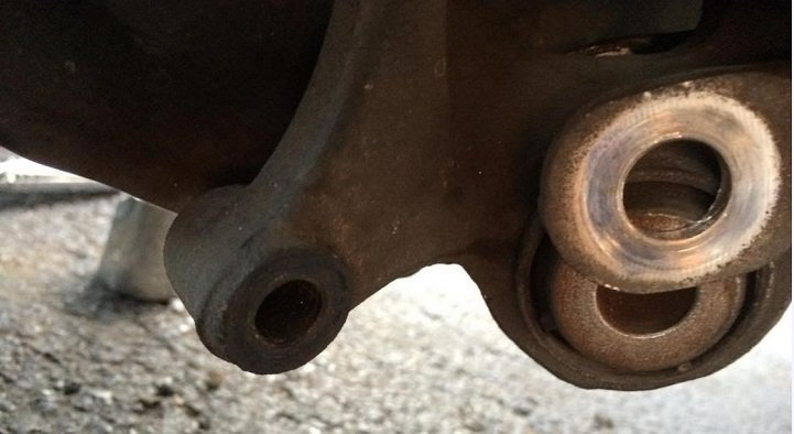
Figure 12. Remove rear sway bar. 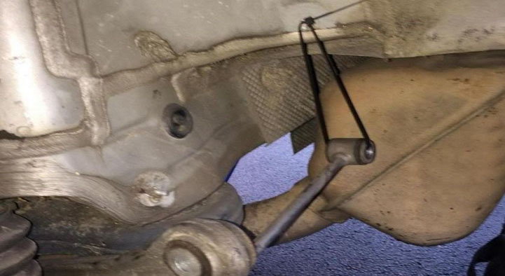
Figure 13. Use a zip tie to hold the rear tow arm up and out of the way.
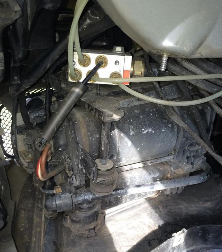
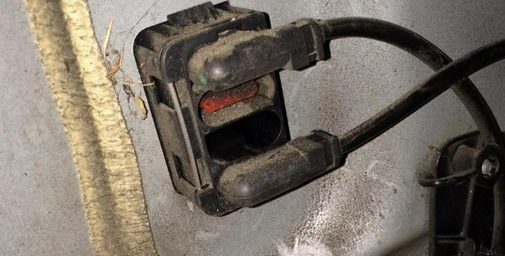
Step 12 – Remove hydraulic control line
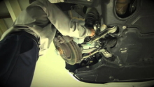
Trace the line coming from the rear shock over to the junction box mounted to the body of the car. There will be three connections, use a flat head screwdriver to remove the middle connection only.
Step 13 – Remove rear shock and air bladder
Remove the lower mounting bolt from the lower control arm. Get into the trunk and pull the liner from the rear wall. Use a flat head screwdriver to pop the plastic tabs out. Be careful not to destroy the tabs when you are removing the liner. Once the liner is removed, remove the three tower bolts. The shock should drop right down, and can be removed out through the rear wheel well. Cut the large air supply line for the bladder and the bladder will compress like an accordion as the air escaped through the supply hose you just cut. Remove the lower mounting bolt for the air bladder, locate the factory (white) air feed line and cut it. Unclip the harness from the bladder and the entire bladder assembly can now be removed.
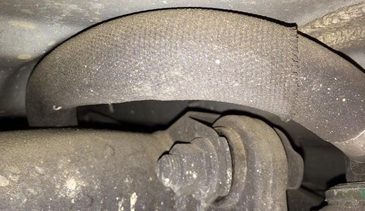
Figure 15. After the shock is removed, cut into this hose to remove the air bladder. 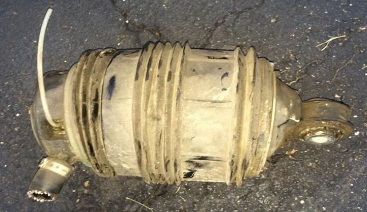
Figure 16. Air bladder finally removed.
Step 14 – Remove the lower control arm
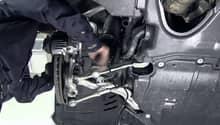
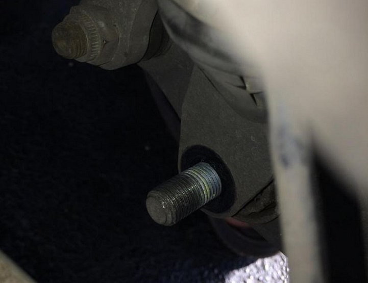
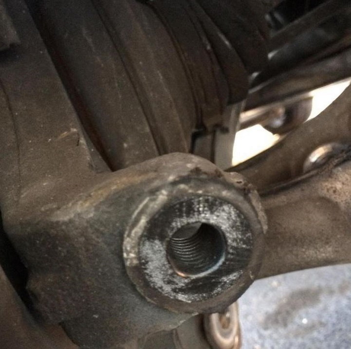
Remove the bolt at the spindle, and then remove the control arm bolt mounted to the chassis. Now go ahead and remove the lower control arm.
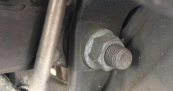
Figure 17. Remove the spindle bolt from the control arm. 
Figure 18. Remove the control arm mounting bolt from the chassis body.
Step 15 – Install new control arm and new coilover
Install the new control arm that integrates with the coilover kit. Install the new coilover shock. Mount the upper tower mounting bolts and then mount the lower bolt to the lower control arm. Reinstall the camber arm, toe arm, sway bar, trunk liner and fender liner. Lastly reinstall the rear wheels, drop the car and tighten the lugs to the manufacturer's recommendation.
Related Discussion
- My E55 Coilover Install with Step by Step - MBWorld.org