
Finally fixing my balance shaft!
 08-04-2013, 12:03 PM
#26
Super Member
Thread Starter
Join Date: Dec 2008
Location: MD
Posts: 526
Likes: 0
Received 1 Like
on
1 Post
2007 C230 and 1985 Monte SS
There appear to he two head bolts just under the cam adjusters that fasten into the timig cover. The problem is that you cant get to these without first removing the cams, and the exhaust cam is held by the timing chain which cannot be removed without removing the timing cover. Looks like tou do need the special swivel sockets from the tsb afterall.
 08-04-2013, 02:02 PM
#27
Super Moderator

 08-04-2013, 02:17 PM
#28
MBWorld Fanatic!

Good luck!
08-04-2013, 06:31 PM
#29
Super Member
Thread Starter
Join Date: Dec 2008
Location: MD
Posts: 526
Likes: 0
Received 1 Like
on
1 Post
2007 C230 and 1985 Monte SS
I hope its from the sprocket, but we cant get the timing cover off without the special wrenches from the tsb so i havent laid eyes on the balance shaft yet. Any suggestions on what else to look at?
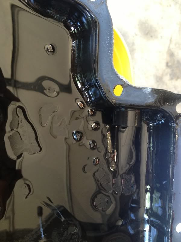
Those pieces would never be apparent during an oil change because the drain is elevated from the bottom of the oil pan.
Those pieces would never be apparent during an oil change because the drain is elevated from the bottom of the oil pan.
08-07-2013, 08:21 PM
#31
MBWorld Fanatic!

That looks like a real PITA.. good luck with it.. looks like you and your friends are very proficient.
That's a factory defect if I've ever seen one, by the way.
That's a factory defect if I've ever seen one, by the way.
08-09-2013, 11:23 AM
#32
Super Member
Thread Starter
Join Date: Dec 2008
Location: MD
Posts: 526
Likes: 0
Received 1 Like
on
1 Post
2007 C230 and 1985 Monte SS
Thanks guys. I don't know what has to happen for MB to own up to this mistake, but this isn't right. It seemed like the class action against them was dismissed because there was never any proof that it was a factory defect. Maybe a hardness test of the defective sprockets is in order, but I'm sure we would need a significant sample of defective sprockets to prove the case.
Anyways, my buddy was able to source a 1/4" drive E12 (I think was the size at least) swivel socket, so hopefully we can get back into it this weekend and get that timing cover off. I really don't like the idea of removing head bolts with a 1/4" swivel socket... but there's no way around it.
Anyways, my buddy was able to source a 1/4" drive E12 (I think was the size at least) swivel socket, so hopefully we can get back into it this weekend and get that timing cover off. I really don't like the idea of removing head bolts with a 1/4" swivel socket... but there's no way around it.
08-10-2013, 04:41 PM
#34
Super Member
Thread Starter
Join Date: Dec 2008
Location: MD
Posts: 526
Likes: 0
Received 1 Like
on
1 Post
2007 C230 and 1985 Monte SS
Got the bolts loosened with a swivel E12 on a 1/4" x 6" extension and had to rotate the engine around to get the bolts out.
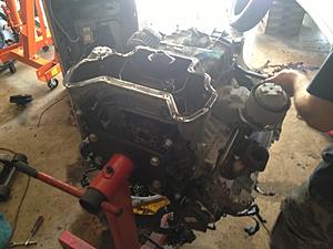
Then removed the timing cover. There is a chain tensioner hidden behind the alternator that you are supposed to take out first but we didn't spot it. I think its ok though.
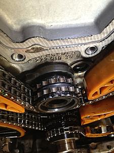
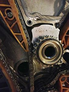
So we finally got a look at the balance shaft sprocket.


Then removed the timing cover. There is a chain tensioner hidden behind the alternator that you are supposed to take out first but we didn't spot it. I think its ok though.
So we finally got a look at the balance shaft sprocket.

 08-10-2013, 05:27 PM
#36
Super Member
Thread Starter
Join Date: Dec 2008
Location: MD
Posts: 526
Likes: 0
Received 1 Like
on
1 Post
2007 C230 and 1985 Monte SS
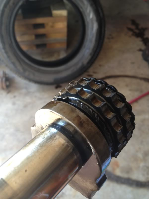
Looks like some of the bits in the pan are just those black plastic pieces and others ar bits of teeth.

The sprocket teeth are all chewed up and rough.
We found info on timing the intake cams to the crank and balance shaft, but not for timing to exhaust cams to the intake cams. Any ideas?
08-11-2013, 01:32 PM
#38
Super Moderator
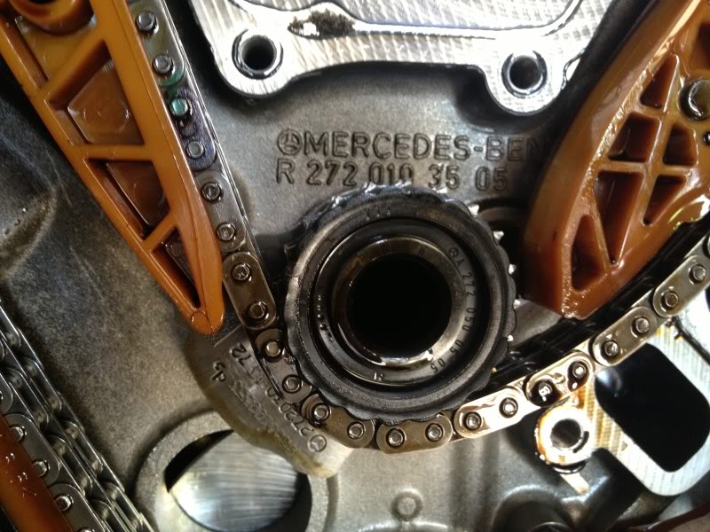
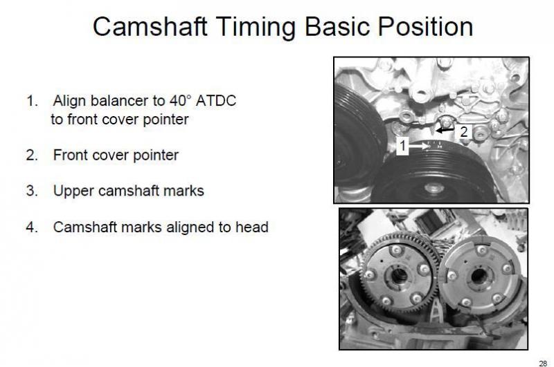
Static cam timing
SSM ~ sorry the second picture is not very clear. Can you look closely. See cam alignment to head (12 o'clock) & then alignment to one another (3 o'clock & 9 o'clock)
08-29-2013, 09:42 AM
#41
MBWorld Fanatic!
I know you located the parts you need for this job - I am just trying to add information to the Post - for future searchers.
I just learned that a family friend had this repair performed on her E350.
Dealer parts list attached.
I just learned that a family friend had this repair performed on her E350.
Dealer parts list attached.
09-17-2013, 06:33 AM
#42
Super Member
Thread Starter
Join Date: Dec 2008
Location: MD
Posts: 526
Likes: 0
Received 1 Like
on
1 Post
2007 C230 and 1985 Monte SS
I plan on adding a final list of parts as well when we finish the job.
Does anyone know if I have really ruined my exhaust cam gear by removing it without pinning the backlash gear/spring? The cost of that part is almost equal to the sum of all of the other parts. I was hoping I could weld up a tool to reset the gear and pin it.
Does anyone know if I have really ruined my exhaust cam gear by removing it without pinning the backlash gear/spring? The cost of that part is almost equal to the sum of all of the other parts. I was hoping I could weld up a tool to reset the gear and pin it.
09-22-2013, 03:40 PM
#43
Super Member
Thread Starter
Join Date: Dec 2008
Location: MD
Posts: 526
Likes: 0
Received 1 Like
on
1 Post
2007 C230 and 1985 Monte SS
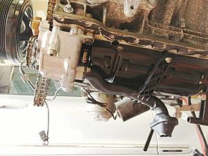
Got the oil pan off. Had to lift the engine with the hoist because the lower two mounts on the engine stand were in the pan. R&R'd the oil pump and pickup tube.
I also managed to get the exhaust cam gear reset.
But now we are stuck on the balance shaft install. The guide wont let the BS sprocket go past the timing chain. Do I really have to break the chain just for this?? It looks like the top pin of the guide can be removed with a slide hammer as it is threaded on the inside. The lower pin is solid though and it doesnt stick out far enough to grab. Removing the top pin wont give me any more clearance at the BS sprocket. So frustrating...

I also managed to get the exhaust cam gear reset.

But now we are stuck on the balance shaft install. The guide wont let the BS sprocket go past the timing chain. Do I really have to break the chain just for this?? It looks like the top pin of the guide can be removed with a slide hammer as it is threaded on the inside. The lower pin is solid though and it doesnt stick out far enough to grab. Removing the top pin wont give me any more clearance at the BS sprocket. So frustrating...
Last edited by SickSpeedMonte; 09-22-2013 at 03:43 PM.
09-23-2013, 11:03 AM
#45
Super Member
Thread Starter
Join Date: Dec 2008
Location: MD
Posts: 526
Likes: 0
Received 1 Like
on
1 Post
2007 C230 and 1985 Monte SS
I found a video on youtube, search "M272 7 minutes", and it will have a time-lapse of a build in just over 7 minutes. The guy uses a pair of channel lock pliers to get the master link through the "lock washers" as I have seen them claled. Then he uses a hammer and dolley to mushroom the ends of the pins so that it cannot back out.
I'm going to try to take some bolt cutters to the old chain to get it off and then install the new one. I hope I get the timing right on the cams/crank/BS on the first try because I don't think it will be easy to get that master link out. I'll run the engine around a couple revolutions before I hammer down the pins just in case.
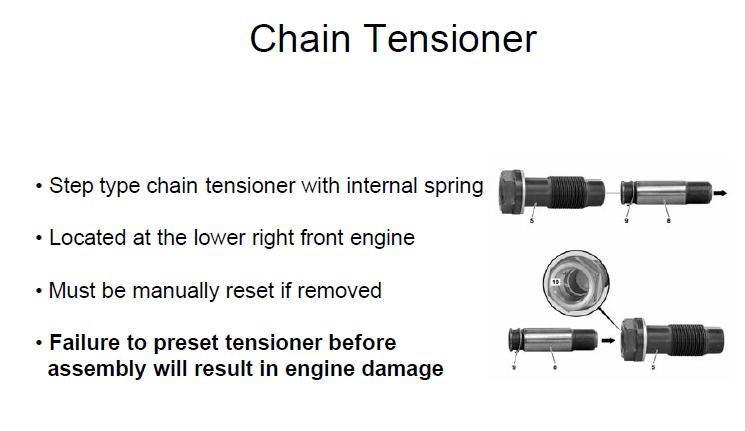
I also have a new chain tensioner. It is retracted right now so it will install fine, but I'm not really sure about how to release it once it's in. My friend said that they usually tap it with a screwdriver and it will pop out.
In any case, I'm going to try to document this process as best I can while it goes back together. From that, I can show how it came apart and make this a little easier on anyone else who wants to try their hand at it. The biggest thing is just knowing what tools to have on hand and knowing of a couple mistakes that you shouldn't make. It's incredible how scattered (and at times, unclear) the information is currently.
I'll get pictures of each part and give a description and the P/N, as that was one area that was difficult to figure out. If you look up the MB P/N, you get a very bare-bones description (i.e. 'Seal', but no idea what it's to). Hopefully I can save someone else $5,000 and minimize the profit that MB makes on this defect. I think that this could be accomplished in a long weekend if you had everything together at the start and knew what to do.
Maybe I'll make a video, that seems like it would be easiest.
I'm going to try to take some bolt cutters to the old chain to get it off and then install the new one. I hope I get the timing right on the cams/crank/BS on the first try because I don't think it will be easy to get that master link out. I'll run the engine around a couple revolutions before I hammer down the pins just in case.
I also have a new chain tensioner. It is retracted right now so it will install fine, but I'm not really sure about how to release it once it's in. My friend said that they usually tap it with a screwdriver and it will pop out.
In any case, I'm going to try to document this process as best I can while it goes back together. From that, I can show how it came apart and make this a little easier on anyone else who wants to try their hand at it. The biggest thing is just knowing what tools to have on hand and knowing of a couple mistakes that you shouldn't make. It's incredible how scattered (and at times, unclear) the information is currently.
I'll get pictures of each part and give a description and the P/N, as that was one area that was difficult to figure out. If you look up the MB P/N, you get a very bare-bones description (i.e. 'Seal', but no idea what it's to). Hopefully I can save someone else $5,000 and minimize the profit that MB makes on this defect. I think that this could be accomplished in a long weekend if you had everything together at the start and knew what to do.
Maybe I'll make a video, that seems like it would be easiest.
Last edited by SickSpeedMonte; 09-23-2013 at 11:05 AM.
09-23-2013, 12:02 PM
#46
Super Moderator
SSM ~ Watch the Star Media video playing in the background with sub titles to release tensioner properly.
Ignore the jerks.
Good luck!
Ignore the jerks.
Good luck!
 09-24-2013, 07:59 AM
#48
Super Member
Thread Starter
Join Date: Dec 2008
Location: MD
Posts: 526
Likes: 0
Received 1 Like
on
1 Post
2007 C230 and 1985 Monte SS
Thanks again for the help Glen.
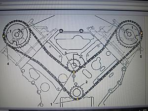
We made a little more progress last night. Took a pair of bolt cutters to the chain and got the old chain off. The new chain has 4 colored (copper) links. We fed the chain through a few different ways and couldn't figure out how to make those links line up with the marks on the cam sprockets, BS sprocket, and crank sprocket.
There really is no mark on the crank sprocket... The directions say to align the crank at 40* ATDC which puts the keyway at nearly 12:00. We thought that maybe the colored link should go opposite the keyway.
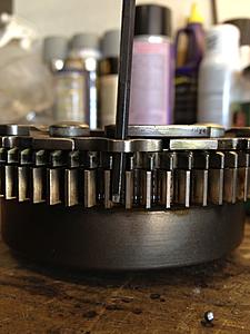
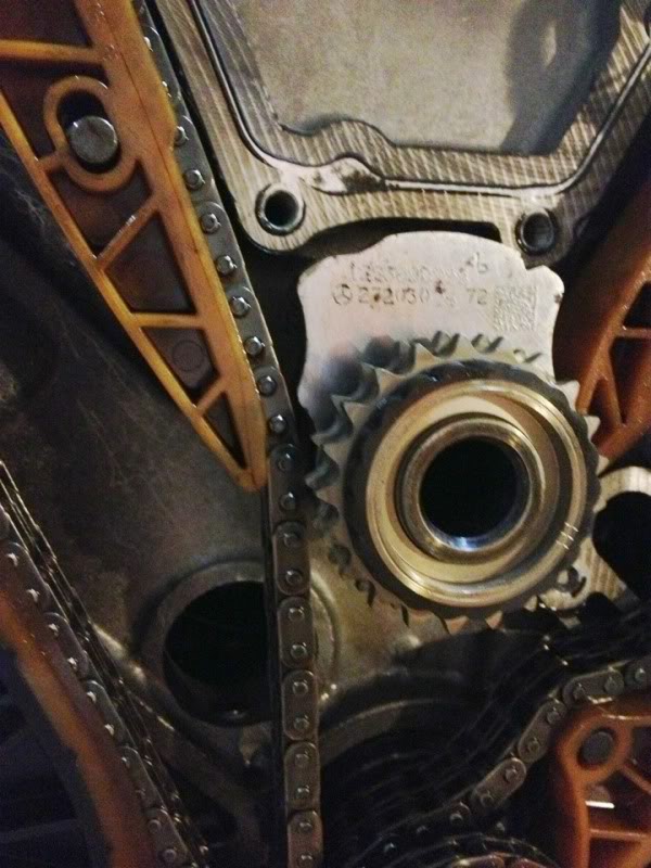
Either way, we couldn't even get two links to line up from either cam sprocket to the BS sprocket. The BS sprocket has three marks on it as you can see above, which end up at the 6:00 position when the notch on the counter weight is lined up with the cast-in mark on the block. That seems to make sense.
There are three marks on each cam gear. The two marks that are opposite eachother go in line with the plane of the deck of the block/head and the third goes up (perpendicular to the plane of the head, 90* from the other two.) We didn't notice any other marks, so we thought that the colored link probably goes on that top mark.
I'm sure there were combinations that we didn't try, but it is pretty cumbersome getting that chain past the sprockets near the head castings and b/w the BS sprocket and that one guide. The directions that I have read say to make the marks on the old timing chain, as if to re-use it, so not much help there. The combinations that we did try put the end of the chain at one of the two intake cam sprockets. There was a colored link right near the end. I'm thinking I'll take some string and try to get the length between the sprocket teeth so that I can compare it to the chain and maybe figure out how it goes.
Also, one thing that kind of doesn't sit right with me. When you align the intake cams such that the marks on the gear are where the directions say they should be, the rear-most cylinder on the right side ends up right at maximum valve lift, making it very difficult to hold the cam there. That can certainly be worked around, and I guess at least one cylinder's lobes have to be off of the base circle, so maybe I'm worried over nothing.
We made a little more progress last night. Took a pair of bolt cutters to the chain and got the old chain off. The new chain has 4 colored (copper) links. We fed the chain through a few different ways and couldn't figure out how to make those links line up with the marks on the cam sprockets, BS sprocket, and crank sprocket.
There really is no mark on the crank sprocket... The directions say to align the crank at 40* ATDC which puts the keyway at nearly 12:00. We thought that maybe the colored link should go opposite the keyway.
Either way, we couldn't even get two links to line up from either cam sprocket to the BS sprocket. The BS sprocket has three marks on it as you can see above, which end up at the 6:00 position when the notch on the counter weight is lined up with the cast-in mark on the block. That seems to make sense.
There are three marks on each cam gear. The two marks that are opposite eachother go in line with the plane of the deck of the block/head and the third goes up (perpendicular to the plane of the head, 90* from the other two.) We didn't notice any other marks, so we thought that the colored link probably goes on that top mark.
I'm sure there were combinations that we didn't try, but it is pretty cumbersome getting that chain past the sprockets near the head castings and b/w the BS sprocket and that one guide. The directions that I have read say to make the marks on the old timing chain, as if to re-use it, so not much help there. The combinations that we did try put the end of the chain at one of the two intake cam sprockets. There was a colored link right near the end. I'm thinking I'll take some string and try to get the length between the sprocket teeth so that I can compare it to the chain and maybe figure out how it goes.
Also, one thing that kind of doesn't sit right with me. When you align the intake cams such that the marks on the gear are where the directions say they should be, the rear-most cylinder on the right side ends up right at maximum valve lift, making it very difficult to hold the cam there. That can certainly be worked around, and I guess at least one cylinder's lobes have to be off of the base circle, so maybe I'm worried over nothing.
09-26-2013, 06:27 AM
#49
Junior Member
Join Date: Sep 2007
Location: Ft Lauderdale, Florida
Posts: 51
Likes: 0
Received 1 Like
on
1 Post
1993 400E
I'll check WIS for those chain marks.
Indepndent shops claim to break that guide to install the BS.
I don't now if their replacing it, or removing enough to install the BS.
Will post up soon.
Indepndent shops claim to break that guide to install the BS.
I don't now if their replacing it, or removing enough to install the BS.
Will post up soon.
Last edited by clarkz71; 09-26-2013 at 09:52 AM.
09-26-2013, 10:20 AM
#50
Junior Member
Join Date: Sep 2007
Location: Ft Lauderdale, Florida
Posts: 51
Likes: 0
Received 1 Like
on
1 Post
1993 400E
OK, for some reason, WIS only shows the M112/M113 chain picture,
But they do show the copper links, maybe the M272 is close,
Since there's 4 copper links, marks at 3 & 9 o'clock
facing the engine.
6 o'clock on the crank & balance shaft. Again, I'm guessing, but this may help.
I'll keep looking for the actual M272 pic.
But they do show the copper links, maybe the M272 is close,
Since there's 4 copper links, marks at 3 & 9 o'clock
facing the engine.
6 o'clock on the crank & balance shaft. Again, I'm guessing, but this may help.
I'll keep looking for the actual M272 pic.

Last edited by clarkz71; 09-26-2013 at 11:49 AM.


