

Intercooler Pump you didn't know about

 01-06-2014, 02:22 PM
#101
PLATINUM SPONSOR
The MBH pump looks close to the zr1 corvette pump that flows about the best on the market these days (around 900.00 bucks as I recall).
Stewart pumps have a ECU on them and can be tuned or boosted up to really move some water.
Stewart pumps have a ECU on them and can be tuned or boosted up to really move some water.
__________________

E63 Biturbo, UPD Cold Air induction kit, UPD performance crank pulley and UPD adjustable rear suspension with ride height adjustment.
CL55 UPD Cold Air Boost kit, UPD 3000 stall converter, UPD 77mm SC clutched pulley and beltwrap kit, Custom long tubes, UPD crank pulley , UPD suspension kit, UPD SC pulley, Aux. HE, Trunk tank w/rule 2000 pump, Mezeire pump, UPD 5pc idler set, Aluminum rotor hats.
www.ultimatepd.com
instagram @ultimate_pd
facebook.com/ultimatepd
 01-06-2014, 06:26 PM
#102
MBWorld Fanatic!

I compared the big EMP pump here:
https://mbworld.org/forums/5836390-post123.html
 01-09-2014, 01:07 PM
#103
Super Member
01-10-2014, 03:41 PM
#104
MBWorld Fanatic!
01-10-2014, 06:18 PM
#105
Super Member
01-10-2014, 08:24 PM
#106
MBWorld Fanatic!
01-15-2014, 01:14 PM
#107
Super Member
01-15-2014, 06:34 PM
#108
MBWorld Fanatic!
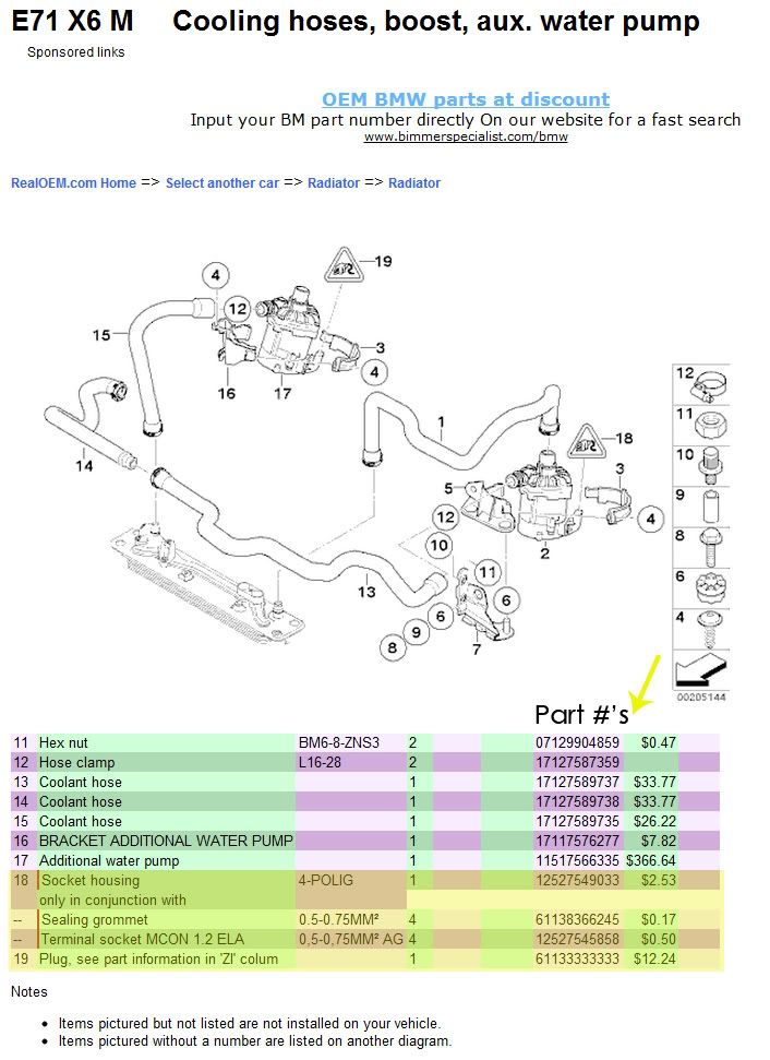
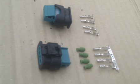
These are the parts I ordered from my BMW dealer:
1 x 12527549033 Plastic Socket Housing
4 x 61138366245 Rubber sealing grommets
4 x 12527545858 Individual Socket Pins
The 61133333333 part number is not meaningful - it just means some undefined socket.
Here are the parts that I bought (two sets - one for the car, one for the pump test rig)
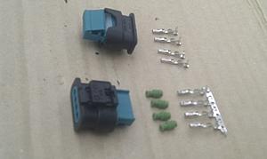
You can probaby crimp the cables to the pins, but I soldered them instead:
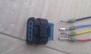
And here's the assembled connector:
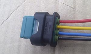
My car's now running with the CWA-100/AMG pump, and is all the better for it - the power is always there, which I could never say before.
I also have a swirl pot / header tank to fill and check the IC system. I'm trying to get a picture of that in action, so to speak, but it's difficult to photograph. Suffice it to say that I finally have little jets of water squirting into the tank, so I can see that the pump is forcing coolant to the top of the system, and the old test ports are now bleeding any air into the tank.
After a good hard run with as much WOT as I dared tonight, my IC's were cool to the touch.
Nick
1 x 12527549033 Plastic Socket Housing
4 x 61138366245 Rubber sealing grommets
4 x 12527545858 Individual Socket Pins
The 61133333333 part number is not meaningful - it just means some undefined socket.
Here are the parts that I bought (two sets - one for the car, one for the pump test rig)
You can probaby crimp the cables to the pins, but I soldered them instead:

And here's the assembled connector:

My car's now running with the CWA-100/AMG pump, and is all the better for it - the power is always there, which I could never say before.
I also have a swirl pot / header tank to fill and check the IC system. I'm trying to get a picture of that in action, so to speak, but it's difficult to photograph. Suffice it to say that I finally have little jets of water squirting into the tank, so I can see that the pump is forcing coolant to the top of the system, and the old test ports are now bleeding any air into the tank.

After a good hard run with as much WOT as I dared tonight, my IC's were cool to the touch.
Nick
The following users liked this post:
NH_E63 (08-10-2022)
01-16-2014, 03:07 AM
#110
MBWorld Fanatic!
1 and 4 are the power wires, and 2 and 3 are the control connections. In a stock application, 2 & 3 would be connected to the ECU. In my case, I have a customised Tecomotive programmable pump controller, which allows me to change the target temperature, or to override the pump control altogether. It can also do a real time display of IC coolant temp, or pump speed, so its a great toy. See my sig.
In any case, pin 4 is definitely battery, but for everyone else who doesn't use a Tecomotive or similar, I would connect pin 3 to your control line (ignition or ECU or whatever).
I wanted to be able to confirm the right connection to use, but I also wanted to find a better source for the connector itself. All I could come up with were those part numbers, so its got be a BMW dealer.
Nick
03-15-2014, 02:59 PM
#111
Member

Join Date: Dec 2010
Location: Wollongong, sydney Australia
Posts: 79
Likes: 0
Received 1 Like
on
1 Post
R170 99SLK230 + SLK32
Looking at CWA50 for SLK32....Good price @$266
http://bmwfans.info/parts-catalog/E7...aux_water_pump
After reading a lot of Welwynnick's post over the past 24 (and thank you!) I'm heading towards the CWA50 or 100.2
I think this one in the link is the CWA50.???
As it stands, based on Nick's system curve, the CWA100 will drive up the pressure for a gain in flow from 5.5 to about 7GPM. If I'm currently getting 2GPM (don't laugh), then 5.5 should be a good step unless I can get a good price on a CWA100.
I was heading down the road of the JohnsonCM90/20mm for ~5GPM but cant find a price like $266 for this one in the link and I get 5.5.
I've got a stock IC and HX at the moment ~2L vol.
My test rig (pictured) has some electronics hooked up to an arduino and LCD and I hope to move all this into the SLK32 for monitoring and calc. kW heat removal. I have in/out temps, flow rate (=-kW removed) and a pressure transmitter as well as a 0.01 Ohm shunt for current measurement + volts measurement.
I'm also planning on hooking up my industrial vacuum cleaner to the Intercooler (centre) and then running hot water through the unit to measure dT versus Water and air flow rate. I've got a MAF from my SLK230 to measure air flow, but that'll only be indicative as I'll only be able to get into ~150cfm range. A gas powered Leaf blower might be the next step.
I'd like to hook in a front HX into the circuit and measure total drops/eff., but gotta find one yet.
I have a 60Amp PWM module on the side, but haven't hooked it up yet because this present test pump doesn't need any SLOWING DOWN....it needs speeding up! The PWM would be handy for a big CWA100 as long as it doesn't mind 16kHz PWM on the raw volts rather than a comms to manage it internally - should be fine.
I've only got stock 0.75mm2 pump cables on my SLK32 and 10Amps would be testing the friendship for the CWA100, PWM maybe helpful here for starting currents.
SPIT!!!
I've tried one of the supposed "ford lightning pumps" - what a waste! - on my test rig I'm only getting 10lpm at 0.7mH discharge pressure.
Robbed!
It may even be a rebadged piece of junk as it doesn't comply with any of the curves I've seen for the same pump. Still in negotiations with the seller to get my money back.
PS - the Stuart 12/50 is a candidate as well.....
Last edited by Billy22Bob; 03-15-2014 at 03:06 PM.
03-20-2014, 10:12 PM
#112
Newbie

Join Date: Mar 2014
Posts: 5
Likes: 0
Received 0 Likes
on
0 Posts
Almost anything with 4 wheels
Added pump info
Thought you might want to know that more pump data, including some of the Stewart and Davies Craig pumps along with testing different voltages, was posted to some of the links you mentioned:
http://www.lingenfelter.com/LPEforum...pump-test-data
and here:
http://www.yellowbullet.com/forum/sh...=564702&page=5
http://www.lingenfelter.com/LPEforum...pump-test-data
and here:
http://www.yellowbullet.com/forum/sh...=564702&page=5
I've been learning a lot about intercooling in this thread:
https://mbworld.org/forums/m275-v12-...n-pumps-5.html
But other people have been doing some fantastic work as well:
http://www.lingenfelter.com/LPEforum...esting-results
http://caddyinfo.com/wordpress/gonna...ling-motorama/
Although these tests were performed on different cars: Mercedes, Cadillac & Chevy, there's a very clear conclusion to be had, and a new direction to look for suitable IC pumps.
IC systems are quite unlike engine cooling systems (or buckets of water for that matter). They're all HIGH RESISTANCE systems, so they need a lot of pressure to achieve good flow. Many pumps are rated for open flow, with no load, but that's almost totally useless for chosing an IC pump. If you want to use a single figure, the static pressure (maximum head) gives a better indication of improved performance, but pumps are more complicated than that, and you really need proper flow vs pressure curves, which is where the Lingenfelter tests are so useful.
There's a lot of talk about 20 gpm pumps, but 3-4 gpm is quite normal in the real world, and 5 gpm is a good figure. Its actually quite difficult to get even that high - I spent several days trying - and a high antifreeze concentration, an uncharged battery, or a tiny bit of air in the system, really knocks it back.
What this means is that pumps that are suitable for engine coolling, or that do well with the bucket test, aren't really suitable for IC systems. So that includes pretty much all Johnson, Meziere & Davies-Craig pumps. So that means that all the forum favourites, like the EWP-80, WP136, CM30 or even CM90, are no improvement on the Bosch. Many people swear by the Jabsco 50840, but even that's a high-flow/low pressure pump.
In my searches, I did find a couple of other likely 20gpm+ candidates - the Dayton 5PXX0 and the SURflow COMSV012D, but they give much the same performance as the above:
http://www.drillspot.com/products/13...ton_5PXX0_Pump
http://www.pumpvendor.com/media/shur..._DC_series.pdf
IC systems normally run at around 0.5 bar, and if you want more flow, you need a lot more pressure. So you need to look for pumps that do 1 bar or more, and I found a couple of real candidates. They have 15-20 gpm open flow, but they achieve up to 1.1-1.2 bar, and the installed performance will be better than ALL the above.
The first is an identical twin big brother to the Jabsco 50840, called the 50860. It looks and cost about the same, has less open flow, but much more power, pressure and installed flow.
The other I never heard of before - the FLOJET DC 40/10.
http://www.xylemflowcontrol.com/mari...-item14187.htm
http://www.xylemflowcontrol.com/file...43000-0858.pdf
http://www.aquaintl.com/product_deta...6&item_id=3339
http://www.xylemflowcontrol.com/file...S_950-0676.pdf
They're both monster pumps, bigger even than the Renntech pump, and I would guess similar to the stock Stewart-EMP E2512A that Lingenfelter promote so effectively in the top thread.
Nick
03-21-2014, 08:48 PM
#114
MBWorld Fanatic!
Great work BillyBob, I was planning to build a rig like yours, but a few other things have gotten in the way. You can read about them soon. It will be worthwhile.
Getting your hands on a rig like that is really instructive. With the stock sytem, its difficult to get a feel for how it all works. You need to understand the importance of anti-freeze, voltage, pump control and especially bleeding. Bleeding is critical, and I can't see how Mercedes' procedure can possibly be adequate.
A proper vacuum bleeder will do the job, but that means a vane pump, not a piston pump or an air pump. They just won't do the job. You've got to get the coolant boiling to bleed properly. You can't just stick a bigger pump in there and expect the IAT's to stay lower. How do you know it won't cavitate and stall the pump?
I think the newer AMG cars have a better system.
Nick
Last edited by Welwynnick; 03-22-2014 at 05:21 AM.
03-21-2014, 08:55 PM
#115
MBWorld Fanatic!
The Lingenfelter tests are really valuable, as they tell you the truth about the high-flow engine cooling pumps like the DaviesCraig and Meziere pumps. If they tested the CWA-50 & 100, I think they would show well.
Unfortunately, Lingenfelter use pressure as the independent variable (the horizontal axis) in their charts - unlike EVERYBODY else in the whole wide World.
That makes it difficult for idots like me to translate them to pressure-flow charts. I used to convert imperial quantities to metric, but my more recent charts were dual axis, so I can type in the data as either metric or imperial, and plot them on the same chart against the same scales. Neat.
Sorry, I don't have the time to do that for all those new test results. All the performance figures I have are in post 102 above.
Nick
04-09-2014, 06:25 AM
#116
Member
Join Date: Dec 2010
Location: Wollongong, sydney Australia
Posts: 79
Likes: 0
Received 1 Like
on
1 Post
R170 99SLK230 + SLK32
1 and 4 are the power wires, and 2 and 3 are the control connections. In a stock application, 2 & 3 would be connected to the ECU. ......
....In any case, pin 4 is definitely battery, but for everyone else who doesn't use a Tecomotive or similar, I would connect pin 3 to your control line (ignition or ECU or whatever). .....
Nick
....In any case, pin 4 is definitely battery, but for everyone else who doesn't use a Tecomotive or similar, I would connect pin 3 to your control line (ignition or ECU or whatever). .....
Nick
I've only so far hooked 12V to pins 1&4.
Before I start flaming the guy who sold it to me I thought I'd check a few things.
I checked pin to ground to make sure I have my negative correct.
Nothing. However after removing the charge, it does show a voltage decline across the pins like there is some sort of capacitance at work. I'm thinking it needs a control voltage or something.....
I suspect I need some control on pins 2&3 to get some action - unless someone else has gotten it to work simply off pins 1&4.
What remains though - is what voltage to apply to pins 2&3
here's an extract from a question to teco...
".....
I checked my ground with the chassis of the motor � so negativeto chassis pin.
When I put 12V across pins 1&4 the pump doesn�t run.
I checked current draw by using a 0.01ohm shunt resistor in linewith the positive wire � that�s okay � well, no current = no short.
I�m therefore thinking it�s either 1) open circuit or 2) needs2&3 energised in some way to enable it to run.
I think I read somewhere that pin 2 comes from the car�s ECU (orTinyCWA in your case) whilst pin 3 is the ground for that signal.
Pin 3 to the chassis of the pump isn�t connected (open) � so itmust obviously be a separate ECU ground circuit and pin 2 may need to be liftedto somewhere between 0-5V. Or maybe even 0-12V?? (or something) to get the pumpto run at a certain speed � eg: for 0-5V - 2.5V = half speed......."
will see what happens..
Last edited by Billy22Bob; 04-09-2014 at 03:46 PM.
04-10-2014, 03:49 PM
#117
Member
Join Date: Dec 2010
Location: Wollongong, sydney Australia
Posts: 79
Likes: 0
Received 1 Like
on
1 Post
R170 99SLK230 + SLK32
Got the CWA50 running.....
Sorry Nick if I'm hijacking your thread....
I followed some instructions from another forum....
Attached is a couple of photos of the internals of the CWA200.
Here’s one person’s unconfirmed explanation of the electronics….
fromhere“….As pointed out, that's a 3-phase (see 3 large connections to thewindings) permanent magnet (PM) brushless DC (BLDC) motor. It's "DC"because a circuit, an inverter, with 6 MOSFETs, converts DC to 3-phase AC. Theinverter uses a position (hall-effect) sensor to sense the position of therotor (which has permanent magnets) and flips the phase of the AC at the righttimes (right position) of the rotor to generate torque.
Fun fact, an alternator is the inverse of a BLDC motor if you replace therotor's "electromagnets" with a bunch of permanent magnets.
Many BLDC motors (such as computer fans) just take power and ground and simplyturn the load as fast as it will go which will be a function of how muchvoltage you apply.
As pointed out as well, this particular fan's board may take a DC or a digitalcomm signal to tell the inverter how fast to turn the motor.
The above schematic suggests that pin 3 accepts a pulldown signal, perhaps DC,PWM, or a comm signal. PWM is probably the most likely. You may be able to findthe pump's datasheet or application notes somewhere.
Here's a tip when testing random signal input pins - do not directly connectthem to 12V or gnd. Connect them via a 100 or 1k resistor. The resistor willlimit the current and prevent possible damage. Having said that, automotiveelectronics are protected against connections to 12V and to gnd... Also if youhave a bench power supply with a **** to adjust max current, set it as low aspossible and only turn it up slightly as needed.
Lastly to check your pump, measure the current that it takes into the 12V. Itshould probably between a fraction of a mA to a few mA, if the pump doesn'trun. If it's zero one of the fuses is blown (the little yellow things in thephoto of the guts)
and the original poster (OP) finally got it to work by….
fromhere “….OK gotit to work. Pierburg clued me in to the actual Pin assignments, 1 is supplyvoltage, 2 is PWM input, 3 you don't have to worry about. So after hooking 1& 2 to +12v and waiting about 5 seconds, it turns on. It's the wholewaiting thing that I didn't try. This spins at 3500rpm when pin 2 is set to100duty cycle.
The PWM input does slow it down (after that ~5sec lag) and there is a widerange of PWM frequencies that will work. I wasn't operating the frequencygenerator but the lab guy said he was trying a bunch and it all worked. I canfind out a definite frequency that works.
Is there anyone who can make me a tuneable PWM circuit that uses a coolant tempsensor as an input and allows me to control/tune the coolant/duty cycle curve?Otherwise I may wire it 100% and use a thermostat, but according to the infofrom Pierburg, this is a 30gal/min pump at full tilt.
Or possibly a circuit that isn't closed loop...perhaps a potentiometer thatcontrols duty cycle that I set at whatever, and I can use the AEM to trigger arelay to 100% at whatever coolant temp, perhaps a few degrees before thecooling fans turning on.
+12vdc square wave…”
Here's how I got it to work at 100% duty cycle
I worked out my main earth by measuring resistance from the pins to the pump chassis = ground - that turned out to be pin 1
I knew pin 4 was 12V supply
Now Pin 3 is the 12V PWM signal line so I connected that to the same 12V but used a 1.5k ohm resistor to ensure I didn't get too much current through and damage the PWM circuitry inside the unit. 1.5k ohm at 12V = 8milliAmperes.
Note - I didn't use Pin2
I turned the power on, the pump then thinks for 2 seconds (energises?) and then starts up. I'm assuming at 100% duty cycle.
Someone else suggested - to change the duty cycle I need to square wave the 12V at some predetermined frequency and the pump should calculate the new duty cycle. That's fine - but at what frequency is the next question. Sure you can have half the time off and half the time on = possibly 50% duty cycle but that can happen 1000 times per second or 10 times per second = frequency.
Regardless to say at the inferred 100% duty cycle, compared to the Bosch/Ford lightning pump I tried last week, this pump really rocks. It blew a hose off my test rig and prompted a few leaks.
When it first fired up - the 22lpm rotameter jumped full scale and wacked into the top of the gauge.
eg: at 13V the Bosch pump was doing 1.2psi at 8lpm and 3Amps
at only 11.3V this CWA was doing over 7psi at 16lpm ad 4.2Amps
I cant drive the CWA50 over 11.3V at the moment because its brushless motor restricts me to battery power, whereas the 13V for the Bosch pump was achieved via motor speed controller (chopper) off a 24V supply. The chopper wont work with the PWM controlled brushless pump.
Note the amps = power consumption = inverse of efficiency....
The CWA50 is achieving so much more from 4.2Amps = 50W than the lightning could at 40W. The CWA runs almost silently and the barely gets warm, whereas the Lightning was up to 66degC case temp after 10minutes of running.
Chalk and cheese.
This pump has enabled me to run a 16lpm test on my IC test rig to compliment my 4lpm and 8lpm tests using the Lightning/Bosch pump. But I achieved this 16lpm by actually throttling the discharge valve - I specifically wanted 16lpm. Hence - I may even be able to squeeze out a 23 or 24lpm run with this CWA50.
Full verified results to follow shortly.
PS - I have also purchased a front Heat exchanger (HX) off another SLK32 - its in the mail = Phase 2. No use extracting heat with an IC if you cant reject that same heat via the front HX.
Last edited by Billy22Bob; 04-11-2014 at 02:10 PM. Reason: updated for "tecomotive's indicated pinout order"
The following users liked this post:
zip439 (08-25-2020)
04-13-2014, 10:12 AM
#118
Senior Member

Join Date: Jul 2013
Location: Europe, but from Norway
Posts: 439
Received 46 Likes
on
41 Posts
89 SL500 Silver ,97 SL500 Carlsson 04 Mercedes SL55 AMG , 07 Mercedes SL55 AMG convertedBlack series
Anyone know what the 510 hp, Europe 517 hp 2007 model Sl55 amg use standard ? the flow pr min ? they changed the pump in 2007 on that model as i know
and the Johnsen pump 30 , what does that one flow pr min ?
and the Johnsen pump 30 , what does that one flow pr min ?
04-13-2014, 12:49 PM
#119
MBWorld Fanatic!

Join Date: Jul 2012
Location: Orbiting the planet
Posts: 4,478
Received 1,490 Likes
on
986 Posts
This place is a joke.
Don't overlook the cheaper option of running 2 factory Bosch pumps in series. A little more labor intensive, but flows about 50% more than the single pump, with redundancy if one pump fails.
The following users liked this post:
NH_E63 (08-10-2022)
04-13-2014, 01:04 PM
#120
MBWorld Fanatic!
I'm liking the sound of this option. I'm lost in the wiring of the other ones. Do you split the wiring for the second Bosch pump or take it from another source?
04-13-2014, 02:08 PM
#121
MBWorld Fanatic!
Join Date: Jul 2012
Location: Orbiting the planet
Posts: 4,478
Received 1,490 Likes
on
986 Posts
This place is a joke.
I have a modified intercooler core, single pass, with 3/4" hose throughout the whole system. It was a lot of work, and not sure I really gained anything yet.
Last edited by E55Greasemonkey; 04-13-2014 at 02:14 PM.
04-13-2014, 03:14 PM
#122
MBWorld Fanatic!
Thanks, that helps. So there are no control wires for the stock pump, just power and ground... I can deal with that.
I would like to clear my intercooler core also, but I just haven't got the time to mess with it right now.
I would like to clear my intercooler core also, but I just haven't got the time to mess with it right now.
04-13-2014, 03:34 PM
#123
MBWorld Fanatic!
231-474 SL-class
231-479 SL-class
That will have added about 50% more flow than the Bosch pump.
The CM30 is pretty much the smallest IC pump of all.
See the chart on post #102.
Nick
Last edited by Welwynnick; 04-13-2014 at 03:48 PM.
04-13-2014, 03:37 PM
#124
MBWorld Fanatic!
Nick


