

AUX in on W203 radio modification complete!


Senior Member
Joined: Dec 2001
Posts: 494
Likes: 13
From: Amber waves of grain.
2000 CLK430 Cabriolet
MP3 interface for W208? Scosche FMMOD02 Universal Fm Modulator
I installed one of these in a year 2000 Jeep TJ, and would like to do same on my CLK.
This is not a transmitter/broadcaster. This is a hard wired emitter, patched in-line of the radio antenna cable.
Has anyone installed/used one of these in a W208 year 2000 ? Seems I hear something about fiber optics being an issue with some mp3 units, or something. Any info?
Here's a link to the unit:
Universal FM Modulator for iPod & MP3s and Auxiliary Input Devices
Thanks

Newbie
Joined: Oct 2010
Posts: 3
Likes: 0
2001 c320 Lorinser
Vivaitalia, Sorry for posting on an old thread but...
THANK YOU for posting pictures and providing the normally closed option to this mod!
I just did it last night and I couldn't be happier. This is arguably the best modification this c320 has ever seen! Sound quality is excellent as well for anyone else wondering, and I also wanted to thank you for saving me ~290-400 dollars, which is what those IPOD integration kits are running!
thank you, thank you, thank you!
-First time Benz owner


Newbie
Joined: Apr 2010
Posts: 1
Likes: 0
C230K
Vivaitalia, Sorry for posting on an old thread but...
THANK YOU for posting pictures and providing the normally closed option to this mod!
I just did it last night and I couldn't be happier. This is arguably the best modification this c320 has ever seen! Sound quality is excellent as well for anyone else wondering, and I also wanted to thank you for saving me ~290-400 dollars, which is what those IPOD integration kits are running!
thank you, thank you, thank you!
-First time Benz owner
THANK YOU for posting pictures and providing the normally closed option to this mod!
I just did it last night and I couldn't be happier. This is arguably the best modification this c320 has ever seen! Sound quality is excellent as well for anyone else wondering, and I also wanted to thank you for saving me ~290-400 dollars, which is what those IPOD integration kits are running!
thank you, thank you, thank you!
-First time Benz owner
I newer remove the radio power. Do I need the radio code?

Member
Joined: Apr 2009
Posts: 126
Likes: 0
1990 500SL-2002 C230 Coupe-2012 c250 Sedan SOLD-2012 C63 Coupe
...
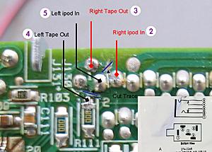
For the life of me I can not figure out which one is tab 1 and tab 3....
Can anybody help me out, is it just the ones listed as Ipod in and out on the closed circuit example?
I just want to do a simply open circuit aux cable with a dummy tape in the cassette player.
Can anybody help me out, is it just the ones listed as Ipod in and out on the closed circuit example?
I just want to do a simply open circuit aux cable with a dummy tape in the cassette player.


Member
Joined: Apr 2009
Posts: 126
Likes: 0
1990 500SL-2002 C230 Coupe-2012 c250 Sedan SOLD-2012 C63 Coupe
...
Thanks I found it and tried plugging it in but got tape stuck, gonna have a computer shop do it for me and just remove the tape functionality as well.
Member
Joined: Apr 2009
Posts: 126
Likes: 0
1990 500SL-2002 C230 Coupe-2012 c250 Sedan SOLD-2012 C63 Coupe
...
The white tab holding my ribbon down is broken on one side and I think that caused a short when I put the radio back in trying to return it to stock.
Will I still get the PROD code with the ribbon taped up with electrical tape to avoid the short as it wont stay in its socket solidly enough to avoid the PROD code.
Hoping to add an amplifier and an aftermarket channel summer like the MTX RE-Q to add an aux socket that way.
Will I still get the PROD code with the ribbon taped up with electrical tape to avoid the short as it wont stay in its socket solidly enough to avoid the PROD code.
Hoping to add an amplifier and an aftermarket channel summer like the MTX RE-Q to add an aux socket that way.

Junior Member
Joined: Dec 2008
Posts: 35
Likes: 0
From: Rochester, New York
2014 E350 4Matic
Cutting the traces stop any signal from the small Sony Integrated Circuit's line out channels from reaching the radio. When the traces are cut another intput can be sent through the same trace.
"1/8th inch jack"
I bought the pretty Monter iPod cable for $35 from Best Buy. When I got home I could not pull myself to cutting it. If the job didn't work I would be out a stereo and a $35 cable. eech. Luckily I found a good sony RCA to 1/8 male adapter that was long enough. I figured it was worth sacrificing. A key point... Another reason I didn't use the monster cable is that it was so large. The soldering points were so small. The Sony cable worked great.
About Crypto's caps..
He recommended removing a cap just south of pin 1. I went ahead and cut the trace right before it. I had a good high quality soldering iron but I didn't have any surface mount desolderers and I thought I could fill my cut trace and get the system working again if need be.
Annoying Beep....
I keep the tape door shut.
Scematic...
I don't have one for the radio. I did find one for the Sony IC that controlled the tape system. I checked Crypto's pins and he was right.
-Good Luck
According to Cryptnotic's quote (#6) there is a surface mount resistor to remove.Did you remove it? If so, which one?


Junior Member
Joined: Apr 2010
Posts: 40
Likes: 1
From: Irvine, CA
2005 CLK55 AMG Coupe
Hi All,
I was just in the process under going Vivaitalia's mod with a close circuit jack when I notice all the pictures have suddenly become unavailable...
PLEASE HELP!!!! I'M DRIVING WITH ALL THE PARTS DANGLING AROUND ><
I was just in the process under going Vivaitalia's mod with a close circuit jack when I notice all the pictures have suddenly become unavailable...
PLEASE HELP!!!! I'M DRIVING WITH ALL THE PARTS DANGLING AROUND ><
Junior Member
Joined: Apr 2010
Posts: 40
Likes: 1
From: Irvine, CA
2005 CLK55 AMG Coupe
Faith in humanity restored!!!
Thank you Vivaitalia for sending me your original pictures and allowing me to repost them again on this thread.
Repost working pictures from Vivaitalia's original post:
Here is my part...
Step 1) Remove the fuse of your radio unit
Step 2) Remove the center trim to pull out the radio. Follow the instruction here http://www.fitaudio.com/?View=entry&EntryID=157 The steps are mostly similar if not exactly the same.
Step 3) Disassemble the radio. Do this slowly and document the order you take away each part and where the crews go on a sheet of paper. I suggest remove the data strip from the board under the cassette mechanism.
Step 4) Cut trace and solder on the 4 wires and number/color code them to these points
(Suggest that after testing with a multimeter you hot glue everything in place for protection and insolation. A thin layer will do otherwise the parts won't go back on due to limited sapce)
Step 5) Loop the wires out first then put everything back. If you chose to ground it you may pick a place on the metal part of the radio case.
Step 6) Solder the wires on to the close circuit jack according to the numbering I've provided.
Step 7) Again Hot glue or epoxy these points.
Step 8) Plug the wires back to the radio and don't forget the fuse under the hood too. Test that everything works for a good 10min before starting to put things back.
**If you are experiencing your radio unit displaying �PROD� after 30sec of turning it on. Pull out the fuse on the back of the radio and plug it back after sometime. This worked in my case since the car recognizes it's the same radio unit.
Notes:
- I couldn't find an other close circuit jack so I had to use the one from RadioShack. Just be fast when soldering since the prong can get hot enough to melt the surrounding plastic and cause it to move out of place.
- I have made it easier for reference by adding the corresponding soldering point on the jack from RadioShack. Ground connection is 1 and not really necessary. Use a ground loop connecter instead.
- I attempted to use audio cable for home theater but it was too stiff to work with. I end up using 2 3.5mm extender to do the job. It works just fine.
- It helps to have a multimeter to check whether you have cut the trace successfully or not and the soldering to the jack.
- I use a hot glue gun to secure and insolate everything, especially the soldering points, because they are really fragile.
BEST OF LUCK!!!

Thank you Vivaitalia for sending me your original pictures and allowing me to repost them again on this thread.
Repost working pictures from Vivaitalia's original post:
lovin_my_C230K's Pictures
https://plus.google.com/photos/11354...84864037634865
* Radio Shack closed-circuit stereo jack *

* my circuit board *

* my stereo jack connected to wires *

* my jack connected to the back of the ash tray *

* my ash tray finished product *

NOTES:
* Find a better closed-circuit stereo jack than the one from radio shack...not very good quality, gets the job done, but inserting the male end of the cord into the female end of the closed-circuit jack will make static noise (if stereo turned on). Sometimes bumping the cord will make a static noise.
* Get sheilded cable. I used security shielded 22/6 (gauge/number of wires) cable from Home Depot, surprisingly, raido shack didn't have it.
* I chose to put it in the ash tray b/c I can hide the cables and my ipod neatly there, gives me quick access to the ipod to change tracks and close to the cirgarette lighter to charge when needed
* I used a sharp "exacto knife" to cut the traces.
Good luck....
https://plus.google.com/photos/11354...84864037634865
* Radio Shack closed-circuit stereo jack *
* my circuit board *
* my stereo jack connected to wires *
* my jack connected to the back of the ash tray *
* my ash tray finished product *
NOTES:
* Find a better closed-circuit stereo jack than the one from radio shack...not very good quality, gets the job done, but inserting the male end of the cord into the female end of the closed-circuit jack will make static noise (if stereo turned on). Sometimes bumping the cord will make a static noise.
* Get sheilded cable. I used security shielded 22/6 (gauge/number of wires) cable from Home Depot, surprisingly, raido shack didn't have it.
* I chose to put it in the ash tray b/c I can hide the cables and my ipod neatly there, gives me quick access to the ipod to change tracks and close to the cirgarette lighter to charge when needed
* I used a sharp "exacto knife" to cut the traces.
Good luck....
Step 1) Remove the fuse of your radio unit
Step 2) Remove the center trim to pull out the radio. Follow the instruction here http://www.fitaudio.com/?View=entry&EntryID=157 The steps are mostly similar if not exactly the same.
Step 3) Disassemble the radio. Do this slowly and document the order you take away each part and where the crews go on a sheet of paper. I suggest remove the data strip from the board under the cassette mechanism.
Step 4) Cut trace and solder on the 4 wires and number/color code them to these points

(Suggest that after testing with a multimeter you hot glue everything in place for protection and insolation. A thin layer will do otherwise the parts won't go back on due to limited sapce)
Step 5) Loop the wires out first then put everything back. If you chose to ground it you may pick a place on the metal part of the radio case.
Step 6) Solder the wires on to the close circuit jack according to the numbering I've provided.
Step 7) Again Hot glue or epoxy these points.
Step 8) Plug the wires back to the radio and don't forget the fuse under the hood too. Test that everything works for a good 10min before starting to put things back.
**If you are experiencing your radio unit displaying �PROD� after 30sec of turning it on. Pull out the fuse on the back of the radio and plug it back after sometime. This worked in my case since the car recognizes it's the same radio unit.
Notes:
- I couldn't find an other close circuit jack so I had to use the one from RadioShack. Just be fast when soldering since the prong can get hot enough to melt the surrounding plastic and cause it to move out of place.
- I have made it easier for reference by adding the corresponding soldering point on the jack from RadioShack. Ground connection is 1 and not really necessary. Use a ground loop connecter instead.
- I attempted to use audio cable for home theater but it was too stiff to work with. I end up using 2 3.5mm extender to do the job. It works just fine.
- It helps to have a multimeter to check whether you have cut the trace successfully or not and the soldering to the jack.
- I use a hot glue gun to secure and insolate everything, especially the soldering points, because they are really fragile.
BEST OF LUCK!!!


Junior Member
Joined: Mar 2013
Posts: 26
Likes: 0
2001 C320
So I think I messed up something, either accidentally, or by the nature of my "incomplete job."
I'm the process of taking everything apart to replace some stepper motor arms for the AC (see the sticky, if you are unfamiliar with the procedure. So I decided to knock out a bunch of things at once so I wouldn't have to take the car apart too many times.
So I took everything apart and took the radio upstairs, took it apart as following in the instruction. There already is a tape in the tape player that is stuck and can't get it out, so I didn't worry that much about eliminating the tape playing capability. I cut the negative wires as shown in this picture

But then I messed when cutting the only rca cable i had, so I decided to be less ambitious about the process and be happy that i took care of the annoying head tape stuck sound. Didn't solder anything, didn't touch any circuits.
Anyway, I go back to see if everything works, I connect everything up (though I forgot the radio connection) and the head unit starts up, but no sound is coming from anything, and it can't see the CD changer. I disconnect everything and realize that the radio wire wasn't plugged in, I plug it in and reconnect everything and now the head unit doens't even turn on.
Tried turning the car on (every other wire was properly connected) and head unit still doesn't work, but SRS light came on.....
Does this mean that I'm effectively committed to soldering a few wires and continue with the mod? My theory is that it detects something wrong with the tape, and freaks out?
Or alternatively, did I mess up my entire unit and have to go buy one off ebay?
Please help -- it will be much appreciated. If you are in the northern virginia & DC area and are down to help, please let me know, i got plenty of beers waiting
2001 C320 with Bose.
I'm the process of taking everything apart to replace some stepper motor arms for the AC (see the sticky, if you are unfamiliar with the procedure. So I decided to knock out a bunch of things at once so I wouldn't have to take the car apart too many times.
So I took everything apart and took the radio upstairs, took it apart as following in the instruction. There already is a tape in the tape player that is stuck and can't get it out, so I didn't worry that much about eliminating the tape playing capability. I cut the negative wires as shown in this picture
But then I messed when cutting the only rca cable i had, so I decided to be less ambitious about the process and be happy that i took care of the annoying head tape stuck sound. Didn't solder anything, didn't touch any circuits.
Anyway, I go back to see if everything works, I connect everything up (though I forgot the radio connection) and the head unit starts up, but no sound is coming from anything, and it can't see the CD changer. I disconnect everything and realize that the radio wire wasn't plugged in, I plug it in and reconnect everything and now the head unit doens't even turn on.
Tried turning the car on (every other wire was properly connected) and head unit still doesn't work, but SRS light came on.....
Does this mean that I'm effectively committed to soldering a few wires and continue with the mod? My theory is that it detects something wrong with the tape, and freaks out?
Or alternatively, did I mess up my entire unit and have to go buy one off ebay?
Please help -- it will be much appreciated. If you are in the northern virginia & DC area and are down to help, please let me know, i got plenty of beers waiting
2001 C320 with Bose.

Newbie
Joined: Jul 2014
Posts: 14
Likes: 0
03 clk55-03 C320-96 M3-97 318ti-87 Suby RX-91 CBR600
I just did this mod yesterday to my wife's 03 C320 sport coupe. Took maybe an hour total from start to finish and we are both happy with the outcome. The audio sounds amazing and being able to play whatever music she wants now is great. If she is happy, Im Happy 
Newbie
Joined: Aug 2014
Posts: 4
Likes: 0
2003 w203 1.8 Hatch
I just completed all my audio upgrades. The only way to leave your tape player in tack is to use an iPod tape adapter. I was able to place one and close the tape door since the cable is very thin. Then just attach a simple bluetooth adapter to the line in. So now you can have all the stock radio functions plus bluetooth!
I changed my door speakers to 6.5 two ways. I used the stock speaker housings by cutting the plastic with a dremel to make the new ones fit tight. I cut the speaker wires for all four door speakers under the door floor cover and ran new wires all the way back to the truck then back again.
Using the head unit speaker outs I connected these to an 200w 4 channel amp with line level adapters. I placed the amp in the right side panel so you don't see it. I found that the direct high inputs on the amp caused a noise in the system. Now we have 50w per channel for the door speakers. Major difference. Of course that wasn't enough. I added a 1200W sub amp and an down fired 10" sub speaker. The amp was placed on top of the spare tire. Power was run from that fuse box on the left side for both amps with 8 gauge wire. Ground bolts at the body were used for ground. The speaker is the same cloth as the rear trunk.
Now we have some serious thumps.
Total cost: $309.00 for everything. Sounds as good as any Bose system if not better. It can rattle the truck!
The question was asked,
can the tape functionality be left intact?
The pics are great!
I'll have to consider doing this.
First need to go back find those instructions for R&R of radio.
BUT despite the wunerful pics, it's still not clear to me where the trace is to be cut. Hard to tell. And thats the part where, you better hope you don't screw up.
(and what does cutting the trace accomplish?)
Also where did you put your 1/8 " jack?
Do you just have a wire hanging somewhere or did you make it nice, put a female plug somewhere?
Also there was mention by Crypto of replacing caps and such.
Did you do that?
I'd really like to have tape too!
What keeps it from making that annoying beep?
Ya know, if it wasn't for that annoying beep it could be possible to use a audio to phoney tape convertor.
Anybody have a shematic for this radio?

Newbie
Joined: Apr 2015
Posts: 11
Likes: 0
2003 c230k
success!
Just wanted to say thanks to everyone in this thread that made it possible. The instructions, the pictures, everyone's comments. I was able to do this last night, relatively quickly. Works great!
Thanks again!
Thanks again!

Newbie
Joined: Mar 2016
Posts: 2
Likes: 0
From: Los Gatos
W203 - C320
Hi All!
First I would like to thank for the instructions and the pictures.
I also started to do it but i made some mistakes and now i stucked.
So first I removed the radio (without casette) and made all the soldering which was required.
Then manually added the casette when it was still on my desk and rotated the smaller motor, till the casette goes down and the head connects to the tape.
I put into the car, but it says after 1 sec, tape stuck...
Then i connected the small engine's wire back, cuz i thought maybe i put the casette in wrong. So just out and in again, disconnect the wire and try it.
No luck... - Tape stuck
Also received some times PROD, which is don't know where to put, cuz all the cables were connected/disconnected properly.
Is it possible that i ****ed up only with that i removed the tape without casette?
What should i try now?
Please help!
Thank You

Newbie
Joined: Sep 2016
Posts: 14
Likes: 0
2003 CLK240 (W209) Coup�
Thank you.
Newbie
Joined: Mar 2016
Posts: 2
Likes: 0
From: Los Gatos
W203 - C320
Newbie
Joined: Sep 2016
Posts: 14
Likes: 0
2003 CLK240 (W209) Coup�
I have this seen this pdf but it'not understandable to me:http://www.benzworld.org/forums/atta...t-retrofit.pdf
As far as I understand I have to solder L and R cable to the identified pads but there seems to be more going on in this pdf that I don't understand because it's not explained "for dummies".
Any help appreciated.
As far as I understand I have to solder L and R cable to the identified pads but there seems to be more going on in this pdf that I don't understand because it's not explained "for dummies".
Any help appreciated.

Senior Member
Joined: May 2013
Posts: 415
Likes: 9
2011 E350 Cabriolet
I have this seen this pdf but it'not understandable to me:http://www.benzworld.org/forums/atta...t-retrofit.pdf
As far as I understand I have to solder L and R cable to the identified pads but there seems to be more going on in this pdf that I don't understand because it's not explained "for dummies".
Any help appreciated.
As far as I understand I have to solder L and R cable to the identified pads but there seems to be more going on in this pdf that I don't understand because it's not explained "for dummies".
Any help appreciated.

Newbie
Joined: Nov 2012
Posts: 8
Likes: 0
1998 W140 S320 SWB
To solder the wires, I first removed that ribbon cable. It pulls out after you loosen the connector by pulling 2 white tabs towards the top of the radio. For some reason I could not remove the tape assembly (crazy tight screws!), so the soldering was done in situ. This is a 2 person job unless you have 3 hands. 
After removing that grey metal piece (which is a huge heat sink btw), be sure not to touch this one component that has white thermal paste all over it. I got this stuff everywhere, ick. If you accidentally make a mess, don't worry too much as the stuff isn't conductive so you won't short anything. Yes, I tested it with a multimeter.
As the OP said, White goes to Pin 1, Red to Pin 3.
These pins are TINY. Use the finest tip you can get your hands on. I made sure my wires only had maybe 0.5mm sticking out of the sheath; any more and you risk shorting something out. Of course, I did strip out the outer (black) sheath and twisted a nice length of "ground" wire as well. This gets secured to the outside of the case.
After soldering, I covered the solder points with epoxy. Ghetto but effective way to electrically insulate your work, and to also reduce the risk of future damage!
I then wound my ground cable around that screw, and added some solder to the end of the copper to keep the ends from fraying.
In the 2nd picture, you can see where I ran the red and white wires as well.
Laithtahir@hotmail.com


