When you click on links to various merchants on this site and make a purchase, this can result in this site earning a commission. Affiliate programs and affiliations include, but are not limited to, the eBay Partner Network.
MB W203 C200 K 1998ccm 163HP Automatic Petrol 2000 model
Change Colors in the Instrument Cluster
Hi peeps
Just wanted to brag about the job I've done many said was difficult or for experienced solderer only.
Since my LCD Display began to fade, and when it gets warm I couldn’t read a thing, I bought a new cheap China made display. But the color of the display wasn’t even (see pic 1). So I decided to change the background lightning. I just wanted regular white lights behind the gauges and a blue display. And since the LCD Display is blue by it self, I ordered only white Diodes and red for warning at LedPerf.com.
The manual came in French in a pdf format...and who understand that?
So I had to manually write everything down in Google Translate! But it worked out well.
Since the SMD LED's are soldered on foil I needed to buy a Soldering Iron with adjustable temperature (recommended ca. 15W) and a needle-small tip. And I didn’t want to spend a lot on a Soldering-Station. But I found a Russian made one for 5$ on eBay, and it works like a charm. Be sure to have very thin (0,3-0,8mm) soldering wire with Lead (those Lead-free are useless!), a Flux Pen, De-soldering Pump, Wick and some Anti-Static Stainless Steel Tweezers.
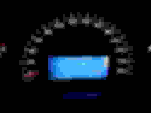
After 3 Liters of wine and 8 hours later I went outside and mounted the Instrument Cluster... and it worked! But because I bought a cheap Display, the color was too bright (see pic 2). So I took it out again and cut a piece from the Anti-Static Bag, which the Display came in (it have a semi-transparent grey color) and placed it between the white back-plate and the diffuser. And voila.... It was spot on with this deep blue color I was aming for (see pic 3)!
MB W203 C200 K 1998ccm 163HP Automatic Petrol 2000 model
Replace of SMD LED's Instrument Cluster and LCD Display on MB W203 C200K 2000 model.
First thing first... “Prepare yourself with everything you need such as LED’s, tools and plenty of time!” You don’t want to rush this delicate operation, so make sure to take many breaks and double-check every LED you have soldered with a Multi-meter! Have your Meter on continuity. The LED will light up if the polarity is correct, with the red wire on plus (+) on the Diode and your black wire in minus (-). Your Meter will also probably make a sound when it got contact. Remember that they work in DC, so polarity is important! The big LED’s have a triangular cut in one corner that marks the so-called Cathode or minus side. The smaller 1206 LED have in the most cases a little green “T” or just a green dot. The underside of the “T” or the dot is the minus-side on them. A little tip is to make a simple drawing of the PCB-Foil/Board on paper, measure the diodes to be sure of the polarity and place them the right way on the paper. But since they are so small, it’s very easy to turn them around if you accidently bump it to them or the table for that matter. So even if you have checked the direction before you put them on the paper, check them again before soldering, and of course after soldering.
That was a little preface, so let’s get to it!
Here are the parts you will need for the job:
LED for Graduations Gauges: 13pcs of LED SMD TL Color: White (or color of your choice) Brightness: 400mcd Viewing Angle: 120 ° Voltage: 3.6 V Dimensions: 3.5mm x 2.8mm x 1.9mm
LED LCD Display (normal lighting): 27pcs of LED SMD 1206 Color: White (or color of your choice) Brightness: 100mcd Viewing Angle: 120 ° Voltage: 3.3V Current: 20mA Dimensions: 3.2mm x 1.6mm x 1.1mm
LED LCD Display (by warning): 27pcs of LED SMD 1206 Color: Red (or color of your choice) Brightness: 60mcd Viewing Angle: 120° Voltage: 2,4V Current: 30mA Dimensions: 3.2mm x 1.6mm x 1.1mm
Original Mercedes have 27pcs of Combo-colored LED's behind the LCD which have the same dimension as the TL type, so they have 4 soldering points which you use two and two for those half-size SMD1206's. Here is a picture I took while soldering:
First you need to take out the Cluster...For that you need some special tools you can buy from a MB Stealer, or you can make your own from a steel clothes hanger, 2mm welding- or piano wire.
Tilt the steering wheel down and out. Insert your magnificent homemade tools in the two slots on both sides of the cluster, with the 90° 8mm angle on the right pointing to the right and the opposite on the left side. Push them inwards until you feel some resistance. Then push about 5-10mm further till it stops. Now you got to turn the left side 90° CW and right side 90° CCW, so they are both pointing up. Now you can gentle pull out the cluster (if you struggle, you can take one side at the time). When the Cluster is out, you can reach the connector on the backside. It has a locking lever that must be lifted up and then the connector can be unplugged and the cluster removed from the vehicle.
Now you can take it inside and prepare yourself for hours of hell
Put the cluster on a clean towel on the table and open the 5 plastic clips one by one as you simultaneously have a gentle pull to it. It’s 3 on the top and 2 at the bottom.
Remove the front and back cover and put them aside.
Next, remove the plastic trim covering the screen, just pull off; there are 5 snaps on the arc.
Disconnect the screen's ribbon; pull the black tabs towards the bottom just to unlock.
Push down the 2 tabs holding the screen. Lift the bottom part up over the tabs and slide towards the bottom, and remove it.
Pry on the plastic clip at the top of these pieces to release them.
Shown in order of assembly (bottom to top), you have the diffuser, the lens and the LCD panel:
Next, the plastic holder for he LCD panel needs to be removed. Use a T10 Torx driver.
After the two screws are removed, the plastic LCD display holder can be removed from the cluster. Next, remove the Mylar circuit board that contains the LED’s away from the speedometer face. It is held in place by snapping onto two plastic studs. Pry gently and it will come loose.
Fold the Mylar circuit board down out of it’s place to expose the speedometer cover.
Remove the speedometer cover by prying on the two plastic tabs on its bottom edge.
The speedometer cover shown removed from the cluster:
You can now see the speedometer needle attached to the servo.
Remove the needles by prying gently from behind or pull gently with your fingers. NB! Before removing the needles, take a photo of their positions to the graduations! They are attached to servomotors with just a round plastic pin, so if you start turning on them, they will not match to their original positions or 0 (zero) when you start the car!
Now it’s just to pry the white corner clips to remove the front plate of the cluster:
And finally remove the white diffuser:
Here are the 13 LED’s you have to de-solder which is the background lighting for the gauges:
When you have removed them all, clean the areas with the de-soldering Wick, so that the surfaces are so to say free from old solder.
Then you are ready to solder the new one’s! NB! Make sure of the polarity is correct, but first use the Flux Pen on the clean surfaces and use your soldering iron with a little solder to cover just one face on the PCB-Foil/LED. You don’t need much, less than you think you need. Grab one LED with your tweezers and hold it in place over the two soldering points (remember only one have a little solder on it, so the LED will tilt a little). Make sure to center it, so the two connection points on the led covers each surface area! Then, with the tip of the soldering iron melt the solder you added for only a couple of seconds. You will feel that LED is sinking slightly. Remove the iron while still holding the LED in place. Then you can simultaneously heat the other side of the LED with some solder. Again, to it quick, so you don’t destroy the LED or the pcb-foil. Test the conductivity with the Multimeter before proceeding to the next LED! Continue with the same procedure for the other LED’s...and don’t forget to take brakes! If you have followed my advice, open the red wine, sit back and relax, and enjoy a glas or two while you take a look of what you have accomplished so far.
When your done with the 13 “big one’s”, it’s time for a real brake! Go away from your surgeons table, fill up your glas and watch something on tv or listen to some music.
And when you feel ready for the next step, fill up your glas again, drink it up and go back to the operation table. Now we are downsizing it! The LED’s for the LCD Display is half the size of the “Big 13’s”, and here comes a new challenge... After you have done the same procedure with removing the old one’s and cleaned the areas from old solder... This time you need to solder those half-size LED’s for the LCD Display side-by-side!
The red LED’s which are for warning is on the left side and the white (normal condition) on the right side in pair, two and two. The red lines on the pictur indicates the minus (-) pole!
NB! In addition, the LEDs is connected in series of 3, so if a LED is badly soldered, incorrectly, or grilled, a vertical line will not work! It happened to me, so I had to make some very thin wires and solder them from another place! It’s a pain in the ***, but it works! So don’t mount everything together before you have tested the lights. Just take your cluster as is and connect it to the cable. Turn your key to position 2 and check every light. Even though you have tested it with your Multimeter, it isn’t shure that the connections are okay! When they are all on, test it for bad connections by pressing light with your finger all over the LED’s. If no one is flickering or fall out, then you can mount everything together in reversed order.
General Tips:
- Put each type of LED in separate bowls or boxes before you begin.
- Be aware of minus/plus when you solder the LED's. It's a very little mark on the LED which indicates minus or plus. I used the Continuity function on a Multi-meter to check the polarity on every one before soldering (just to be safe). They light up when plus on plus and minus on minus. You will probably hear a tone from your meter as well.
- They are very small, and it's easy to drop one, like I did. I did it in the kitchen where I have wooden hard floor...They are so small that you can't hear it when they fall on the floor! Spent a half hour searching for one! So don't do it over a carpet or a floor with cracks or other things the LED's can hide if you drop them.
- Have great lighting when you work.
- I started with the 13 "big one's", so I got used to solder those tiny little things, before soldering the half-size one's.
- Be careful with the heat! The LED's are soldered on thin foil, so if it's to hot, you will melt and destroy the PCB Board or LED! I had my soldering iron on ca. 270°C
- Use plenty of time with the De-soldering Wick to clean of the old solder from the PCB-Board! It will be much easier to solder the new LED's.
- Use the Flux Pen often and put a little solder on the contact-points. Just to cover the copper surfaces and that they are as flat as possible.
- The contact-points on the LED are very tiny and it's important to use the tweezers to hold it steady and flat while heating up one side, but don't heat up too long! As soon as the solder melts, you see and feel the LED is flattening down. Take away the soldering iron quickly, while holding it in place with the tweezers. It should take just a couple of seconds. Wait a little before soldering side two (so you don't over-heat the LED).
And finally the best tip:
- Have plenty of red wine and don't rush it! It's a very delicate job that quickly can cause you to stress. Thus the red wine!
Happy soldering!
Scientific studies show that for illuminated displays white lettering on blue background is the most easy on the eyes and relaxing combination,.... should be better for night driving too,...... and much less stressful than the stock ORANGE warning colour,...
MB W203 C200 K 1998ccm 163HP Automatic Petrol 2000 model
Originally Posted by SunnyRayToronto
I'm impressed!
Scientific studies show that for illuminated displays white lettering on blue background is the most easy on the eyes and relaxing combination,.... should be better for night driving too,...... and much less stressful than the stock ORANGE warning colour,...
Thanks!
I can agree with that! Even though the gradients of the speedometer, rpm and gas-tank meter is now white... The blue LCD Display is more comfortable both day and night. The combination is much better!
I just finished installing the LEDs, I have to say the gauges are pretty dull mine arn't that bright. Do you have any suggestions to get them brighter? (They are all wired correctly and working)
MB W203 C200 K 1998ccm 163HP Automatic Petrol 2000 model
Hm, that is strange...if you bought the TL type with the intensity of 400mcd, they should be bright. The only thing I can think of, is if there is contact between +/- somewhere in the led-circuit to the gauges that causes leakage in current.
just did mine last night took 6 and a half hours looks badass on a c32 amg thanks for the post.
I found it 2 months back and it helped me find what I needed
I had no solder experience and did flawlessly with the guide
the srs got reset with obd
for some reason it went off while working on it so keep that in mind
doing the whole interior white with blue screens on cluster, ac and radio
looks awesome at night way better than stock orange took me roughly 20 hours for everything
Last edited by Romanb2000; 01-02-2022 at 10:13 PM.
Reason: added 1 more pic
 08-01-2016, 05:28 PM


 But because I bought a cheap Display, the color was too bright (see pic 2). So I took it out again and cut a piece from the Anti-Static Bag, which the Display came in (it have a semi-transparent grey color) and placed it between the white back-plate and the diffuser. And voila.... It was spot on with this deep blue color I was aming for (see pic 3)!