When you click on links to various merchants on this site and make a purchase, this can result in this site earning a commission. Affiliate programs and affiliations include, but are not limited to, the eBay Partner Network.
DIY Retrofitting Ventilated AND Air Conditioned Seats with OEM Integration
Hi all. I recently bought a 2019 C300 (Facelift) and have been loving it so far (it's my first Mercedes)
However, the almost entirely black interior, mixed with the Florida sun means an uncomfortably hot and sweaty ride if left outside for any amount of time (remote ignition can only cool the seats down so much).
My car currently has only heated seats, with the perforated MB-Tex. I've heard that the OEM ventilated seats are mediocre, and I aim to fix this by firstly retrofitting the fans, and then ducting A/C in to actually cool down the seats.
I believe I have the technical capabilities to achieve this, so I've decided to take this matter into my own hands and solve this problem, documenting my experience and findings along the way.
I've done extensive research on retrofitting ventilated seats into cars in general, and the most popular solution seems to be the Katzkin Degreez kit. However this option poses a few main problems:
A: It has a separate control module and switches which must be attached somewhere (usually drilling into a trim piece). Which in general looks ugly. I want OEM integration with the switch panel, which in the process gets rid of the blank button.
B: It uses a Peltier module to cool the air, which is extremely inefficient and exhausts more hot air into the cabin.
C: The air distribution pad included takes up almost the entire part of the seat your body is contacting (on both the cushion and the backrest), and as such is much less comfortable than the perforated foam sheets that the OEM seats use.
Where I am so far:
The first major hurdle was to get the car to accept the new switch panel, and integrate it properly. The part number for the switch panel with heating and ventilation is: 2139057402 (for driver's side, passenger is 7602 instead).
Unfortunately, this is not a plug and play process. After installing the new switch panel, programming a few of the car's computer modules was required. This is outside the scope of this post, as you need Xentry, DTS monaco, a J2534 adapter, etc. I bought all of these and paid someone to program the car, so the buttons light up now.
Here's the switch panel: Switch Panel with Vent option (2139057402)
Success! Successful Switch Panel Installation
So now that I have the switch panel successfully installed, I need to get the fans and mesh/foam installed.
The connections to the fans (per the seat control module's WIS diagram) are currently unoccupied in the connector.
Here's the WIS schematic for the seat control module. In particular, this is for connector 3 (far right) and is responsible for the seat cushion's motors.
Here's the image for connector 3:
And here's the wiring diagram for connector 2 (middle) and controls the backrest fans:
Here's the image for connector 2:
Like connector 3, the pins are present on the control module but are not populated in the connector.
It can then be determined that those are the pins necessary to tap in to for the ventilation feature to work.
I did some digging with Xentry, and found that on level 3, the module is expecting no more than 0.5A current draw, which I believe will pose a problem if I connect directly to it. I was intending on using strong fans for the ventilation (high CFM, RPM, and static pressure), and more than 2 per cushion,
so I will have to devise some alternate method for powering the fans.
For the support and air distribution material, I opted for an open air mesh and perforated foam. Each sheet is 1cm in height, so I would need to carve at least 2cm of seat foam away where I want to place the material. I do NOT intend on resurfacing the entire cushion and backrest, as the areas where we contact the most will get crushed and no air can flow anyways.
Picture of mesh:
Picture of foam:
And here's a cross section of what I intend on doing:
Along with my proposed locations of fans/meshing:
These 2 videos show how to de-upholster the seats (though I don't think there's lumbar support in this video, which my car has)
I went underneath the seats and took a few more pictures.
Underneath the seat from the front:
Underneath from the back:
Overall it looks like space is pretty tight for the seat cushion. I have the seats raised up all the way to get enough clearance for the photos. Here's to hoping I can get enough space for proper airflow. Hopefully the backrest has more room, but I haven't got the courage to open it just yet.
As for the air conditioning part, which is half the battle. I plan on tapping into the air duct under the seats to funnel in cooled air to the (soon to be) intake fans. Even though there is not a large amount of airflow from this vent, I believe high airflow fans in conjunction with this cooled air will be more than enough to make the seats continue to be cold to the touch, which is exactly what I want. The caveat is the floor vent setting must be enabled for this to work, and the rear passengers would no longer get the air supply (not that it was strong enough to be meaningful, anyways). An alternative would be to tap in to the center console's rear passenger ducts, but I would not prefer to go this route due to all the cutting and routing it would require. Still an option, though.
The air vent in question:
I'll have to wait for the mesh and foam to arrive before progressing with the seat modifications, as I have to test how much airflow can pass through them, along with testing the fans I'm planning on using.
Hi all. I recently bought a 2019 C300 (Facelift) and have been loving it so far (it's my first Mercedes)
However, the almost entirely black interior, mixed with the Florida sun means an uncomfortably hot and sweaty ride if left outside for any amount of time (remote ignition can only cool the seats down so much).
My car currently has only heated seats, with the perforated MB-Tex. I've heard that the OEM ventilated seats are mediocre, and I aim to fix this by firstly retrofitting the fans, and then ducting A/C in to actually cool down the seats.
I believe I have the technical prowess to achieve this, so I've decided to take this matter into my own hands and solve this problem, documenting my experience and findings along the way.
I've done extensive research on retrofitting ventilated seats into cars in general, and the most popular solution seems to be the Katzkin Degreez kit. However this option poses a few main problems:
A: It has a separate control module and switches which must be attached somewhere (usually drilling into a trim piece). Which in general looks ugly. I want OEM integration with the switch panel, which in the process gets rid of the blank button.
B: It uses a Peltier module to cool the air, which is extremely inefficient and exhausts more hot air into the cabin.
C: The air distribution pad included takes up almost the entire part of the seat your body is contacting (on both the cushion and the backrest), and as such is much less comfortable than the perforated foam sheets that the OEM seats use.
Where I am so far:
The first major hurdle was to get the car to accept the new switch panel, and integrate it properly. The part number for the switch panel with heating and ventilation is: 2139057402 (for driver's side, passenger is 7602 instead).
Unfortunately, this is not a plug and play process. After installing the new switch panel, programming a few of the car's computer modules was required. This is outside the scope of this post, as you need Xentry, DTS monaco, a J2534 adapter, etc. I bought all of these and paid someone to program the car, so the buttons light up now.
So now that I have the switch panel successfully installed, I need to get the fans and mesh/foam installed.
The connections to the fans (per the seat control module's WIS diagram) are currently unoccupied in the connector.
Like connector 3, the pins are present on the control module but are not populated in the connector.
It can then be determined that those are the pins necessary to tap in to for the ventilation feature to work.
I did some digging with Xentry, and found that on level 3, the module is expecting no more than 0.5A current draw, which I believe will pose a problem if I connect directly to it. I was intending on using strong fans for the ventilation (high CFM, RPM, and static pressure), and more than 2 per cushion,
so I will have to devise some alternate method for powering the fans.
For the support and air distribution material, I opted for an open air mesh and perforated foam. Each sheet is 1cm in height, so I would need to carve at least 2cm of seat foam away where I want to place the material. I do NOT intend on resurfacing the entire cushion and backrest, as the areas where we contact the most will get crushed and no air can flow anyways.
Overall it looks like space is pretty tight for the seat cushion. I have the seats raised up all the way to get enough clearance for the photos. Here's to hoping I can get enough space for proper airflow. Hopefully the backrest has more room, but I haven't got the courage to open it just yet.
As for the air conditioning part, which is half the battle. I plan on tapping into the air duct under the seats to funnel in cooled air to the (soon to be) intake fans. Even though there is not a large amount of airflow from this vent, I believe high airflow fans in conjunction with this cooled air will be more than enough to make the seats continue to be cold to the touch, which is exactly what I want. The caveat is the floor vent setting must be enabled for this to work, and the rear passengers would no longer get the air supply (not that it was strong enough to be meaningful, anyways). An alternative would be to tap in to the center console's rear passenger ducts, but I would not prefer to go this route due to all the cutting and routing it would require. Still an option, though.
I'll have to wait for the mesh and foam to arrive before progressing with the seat modifications, as I have to test how much airflow can pass through them, along with testing the fans I'm planning on using.
Looked in Xentry a little more and got some hard numbers for current consumption. The cushion and backrest are 2 separate zones, with different current range expectations. It also appears the output is PWM-based, but I haven't yet gotten a chance to probe the output pins to test that yet.
Here are the current ranges for all 3 settings.
Stage 3 values
Stage 2 values
Stage 1 values
It's no wonder the OEM fans are so pathetic, given the maximum allowed current by the module. This means I'll have to power the fans separately but use the presence of the module's PWM output to control the fans accordingly.
As for fans, I have 2 in mind I plan to test.
Fan 1 is a b-blaster 70mm, which I heard of from this thread about fan upgrades. Seems it has high airflow, high static pressure, and high RPM (at the cost of high noise)
Link:
Fan 2 is the better known Noctua NF-A9 92mm. It also has high airflow, but lower static pressure and lower RPM (in turn producing much less noise)
Link:
I'm going to have to balance airflow and noise, as road noise at highway speeds will likely overpower anything these fans could produce, but lack of airflow is ultimately the most important factor.
I also found some interesting research from a school in Sweden, which tested a slew of cushion, backrest, and thigh support ventilation methods. I will definitely be using their findings when I get to modifying my seats.
Link: Ventilated Seat Paper
In the meantime, I'm waiting for the b-blaster and Noctua to arrive, and will do some noise tests on the road with those when possible
I tapped in to the under seat connections for the first time to measure the voltage coming from the connectors. These connectors are made with a few pieces that slide together with a latch tab at the end.
The tab latches are in the 2 slotted areas on the edge of the connector
More tab latches
I used generic female to male jumper wires with the plastic shroud removed on the female end, and inserted two into spots 11 and 17 for ground and power, respectively.
The pin connectors in those generic wires are slightly too thin and short to properly latch in to the socket, but they worked well enough for testing. If anyone knows the proper dimensions of those pin connectors, please let me know!
For simplicity, I only tapped into connector 2 just to test for voltage.
And…
It’s alive!
The voltage was measured on the highest setting, and both medium and low shows the exact same value. This confirms my suspicion that the output is PWM-based for speed control (hence why the voltage value doesn’t change, since this is a cheapie DMM), so I will need to probe the outputs to get a better understanding of the peak voltage and the PWM frequency.
I tapped in to the under seat connections for the first time to measure the voltage coming from the connectors. These connectors are made with a few pieces that slide together with a latch tab at the end.
I used generic female to male jumper wires with the plastic shroud removed on the female end, and inserted two into spots 11 and 17 for ground and power, respectively.
The pin connectors in those generic wires are slightly too thin and short to properly latch in to the socket, but they worked well enough for testing. If anyone knows the proper dimensions of those pin connectors, please let me know!
For simplicity, I only tapped into connector 2 just to test for voltage.
The voltage was measured on the highest setting, and both medium and low shows the exact same value. This confirms my suspicion that the output is PWM-based for speed control (hence why the voltage value doesn�t change, since this is a cheapie DMM), so I will need to probe the outputs to get a better understanding of the peak voltage and the PWM frequency.
Originally Posted by Cosworth2000
Wow.. this is big job. I show a video on Youtube where a guy did the same things for the Ford car and it looked like a job that scared me.
Ok so I decided to look at the back of the seats today, to get a better idea on the clearance inside, and how much space I have overall. In order to, I needed to remove the backrest cover. Fortunately, there's an official video for this:
Unfortunately, actually removing the backing ended up being hellish. In the video, a special proprietary tool (205589016300) is used to wedge apart the clips holding the backing in place, which looks like this:
In true Mercedes fashion, the various sellers want upwards of $300 for one of these, which is obviously ridiculous. I originally tried using plastic trim removal tools, but none were long enough to reach both of the clips. Then I tried a long flathead screwdriver to try and push away the latch of the clip, which also failed.
My last resort was this:
A 1" x 16" spade drill bit I Dremel'd the top of, to smoothen it out. Fortunately, this worked and I managed to get the back off (I easily spent 2 hours trying different tools, seat angles, tool angles, etc.). So far, this step has been the biggest PITA. Because I did this while the seat was still in the car, I had much less flexibility on where I could angle the tools, so when the time comes to remove them, it should be considerably easier. The silver lining is now that I've done it once, it should be easier the next time, both from experience and the clips softening up.
Here are various pictures of the seat backing and the inside of the seat itself: Inside the back of the passenger seat. The 3 tubes are for what I presume to be the lumbar support's air bag
2 clips near the bottom of the seat backing. So frustrating to unhook!
A few more pictures of the seat clips.
Here's the bottom part of the inside: Looking downwards in the seat
This part is a little concerning, as there are seemingly no gaps to allow any ducting for airflow, so I'll have to look closer when I get around to removing the seats. I'll also get a better view of the bottom cushion, so expect more pictures then.
As for my previous post, soon I'll be probing the voltage output of the control module to get a better idea of how the OEM fans are controlled.
Ok so I decided to look at the back of the seats today, to get a better idea on the clearance inside, and how much space I have overall. In order to, I needed to remove the backrest cover. Fortunately, there's an official video for this:
Unfortunately, actually removing the backing ended up being hellish. In the video, a special proprietary tool (205589016300) is used to wedge apart the clips holding the backing in place, which looks like this: https://cimg8.ibsrv.net/gimg/www.mbw...58802b7280.png
In true Mercedes fashion, the various sellers want upwards of $300 for one of these, which is obviously ridiculous. I originally tried using plastic trim removal tools, but none were long enough to reach both of the clips. Then I tried a long flathead screwdriver to try and push away the latch of the clip, which also failed.
A 1" x 16" spade drill bit I Dremel'd the top of, to smoothen it out. Fortunately, this worked and I managed to get the back off (I easily spent 2 hours trying different tools, seat angles, tool angles, etc.). So far, this step has been the biggest PITA. Because I did this while the seat was still in the car, I had much less flexibility on where I could angle the tools, so when the time comes to remove them, it should be considerably easier. The silver lining is now that I've done it once, it should be easier the next time, both from experience and the clips softening up.
Here are various pictures of the seat backing and the inside of the seat itself: https://cimg0.ibsrv.net/gimg/www.mbw...044a8e113f.jpg Inside the back of the passenger seat. The 3 tubes are for what I presume to be the lumbar support's air bag
This part is a little concerning, as there are seemingly no gaps to allow any ducting for airflow, so I'll have to look closer when I get around to removing the seats. I'll also get a better view of the bottom cushion, so expect more pictures then.
As for my previous post, soon I'll be probing the voltage output of the control module to get a better idea of how the OEM fans are controlled.
Hmmm sounds like the project is getting interesting.
I messed around today and was able to get the passenger�s seat out to get a better look at everything.
Under the thigh support on the passenger side. Seems to have covered much of the foam underneath, which may make airflow difficult compared to the driver�s side.
To properly take out the seat, the wiring harness underneath needs to be disconnected from the SRS and seat control units underneath. Unfortunately, these seem to be attached to the underside of the seat via a barbed zip tie connector, which is far easier to just cut through than to try and re use.
Wiring harness with cut zip tie in the background
While disconnecting everything, I noticed one of the zip tied barb connectors wasn�t ever connected or fell out or something. This didn�t seem to have caused any issues, but as a result I don�t know where it�s originally supposed to attach. It�s must be that �Bama QC at work again. If anyone happens to know the P/N for this, please let me know.
There are 3 connectors that must be disconnected from under the seat. One white connector on the seat control unit, the yellow (I think SRS) connector on top of the seat control unit, and a black connector that I�m not sure the purpose of.
After disconnecting these, I was able to pull the seat out and sit it down on the driveway. The remaining issue was that the seatbelt was still connected to the seat�s frame and it�s obviously necessary to disconnect it to fully remove the seat. Unfortunately, the WIS documentation I found did not have this type of seatbelt attachment mechanism, so the instructions for removal didn�t apply at this point.
T-50 bolt attaching the seatbelt assembly to the seat frame
I ended up using a Torx T-50 bit to remove this from the seat. The remaining problem though was this little colorful connector attached to something in the assembly, with no indication as to how to remove it. After some poking and prodding, I found you just need to wedge a flat head between the orange and cyan to unlock the connector.
While I had the seat gone I took the time to see what the little footwell air vent looked like:
at some point I�ll get around to modeling this piece so I can make a modified version tailored towards my plans for seat conditioning.
Hey all. Have a bit of a mini update for now. Unfortunately, I've hit a roadblock issue I'm trying to find out the cause of.
Simply put, my cars seat control modules (the controllers located under the seat) are not putting out a PWM (or varying analog) voltage from the labeled fan pins. I guess my cheapie DMM was showing its worth when giving me those readings previously.
Instead, I get a constant ~15V on the output between all 3 stages. As a result, the fan runs at max speed constantly. I believe there may be an issue with the coding done to the module, but I do not know.
I've tried troubleshooting this for hours and still haven't gotten anywhere. If anyone has a facelift w205 with ventilated seats and DTS Monaco, PLEASE PM ME
On another (unfortunate) note, I found out which terminals are used in the connectors for the seat control unit.
They even have their own official Mercedes part number! A0165454126
I was so filled with joy upon finding this information that I immediately bought a pack of 9 on the order of $3/piece (you do the math)
Unfortunately, that was before I looked around (for not even 5 mins) on EPC and found that it's nothing more than a generic MQS0 0.63mm automotive terminal, of which I got a 15-sampler pack for $0/piece (you do the math...).
These were used with some generic jumper wire to attach to the fans and also an oscilloscope for probing, which yielded the problem described above.
Speaking of fans, I've decided to ditch my original plans which were between a b-blaster 70mm and a Noctua.
I tested the 70mm b-blaster, and it did not feel sufficient in terms of air pressure and airflow, as well as having a big deadspot of airflow in the center area.
I didn't even bother buying the Noctua, as it has weaker specs than the b-blaster.
Instead, I'll be going with the b-blaster 90x25mm and possibly 90x35mm fan, which have insane specs.
25mm: 78 CFM
5.5 mmH2O
39 db(A)
35mm: 108 CFM
13.5 mmH2O
45 db(A)
These blow the 92mm Noctuas (or any sized Noctua) out of the water, to say the least (besides noise).
I tested the noise while driving with music on, and it was largely unnoticeable (that's with them laying on the floor in the open, too) so I am pretty set with those choices, just have to figure out the aforementioned PWM issue before continuing.
That's where I'm at as of now, still very stuck on the PWM issue.
Hey all, thought I�d give an update on my (lack of) progress. Unfortunately, no matter what I tried, the seat module never gave a proper PWM output I could use. This unfortunately means I have to go with the more difficult method of stage detection.
In the video, the probing shows a brief period of irregular voltage swings (it almost looks like a data packet) before going to 0V and then immediately rising to 15V. Instead of using a PWM output to control the fans, I�ll have to use a MCU to detect these rapid pulses (shown below) and deduce which stage the fans should be at. My theory is it�s trying to detect some level of inductive voltage spiking before fully outputting, but otherwise I have no clue. I tried using a purely resistive load as well, to no avail.
Weird looking voltage switching briefly after changing ventilation stages
Speaking of fans, I have finally arrived on a choice. Due to the previously mentioned lack of seat module PWM output, I have chosen the 90mm b-blaster PWM fans. These will be controlled by a PWM signal output by the MCU (yet to be determined) and as a plus will allow finer speed control than a purely analog voltage could.
After some more looking I figured out that those previously posted waveforms are in fact data packets being sent to the fans. This stumped me for weeks because I was expecting the PWM signal to come from
the seat control module itself (like it does for the resistive heating wire). The data transmission method is unlike anything I have ever seen compared to CAN, LIN, SPI, I2C, etc. protocols where there are dedicated
power connections and separate data transmission wires. Coming from an EE background, that is what I am most used to. I have never seen the system Mercedes uses anywhere else, as it uses the 15V power wire
as a data wire temporarily, presumably to tell the fan's controller IC what speed to run the fans at.
Knowing this, the problem is then decoding these data packets with a dedicated MCU to control my own fans (which lack the controller chip that can read the data natively).
Not caring to try and decode each data packet, I decided to cheat a little to determine which stage the ventilation should be at.
The general waveform output from the fan's connections looks like this:
With my MCU, I detect the rising and falling of these edges to determine which stage the ventilation should be. Instead of decoding the PWM data sent,
I just detect when that PWM data is sent, and change the stage accordingly.
I have already started on the electrical wiring for this, which will be routed under the floorboard. More pictures to come, but the ball is now rolling!
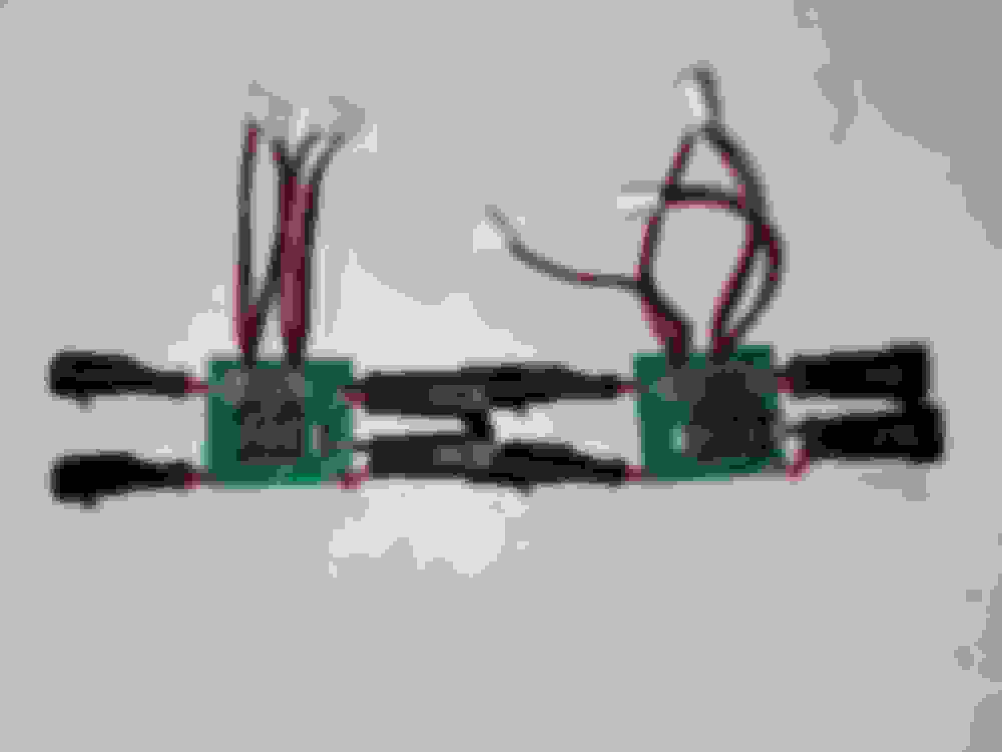
I have nearly finished with everything, and will have the rest of the pictures available in the coming weeks most likely. I took a big break but have regained motivation to continue. All of the electrical wiring is complete, and I've installed it in the passenger side (will do the driver's side when I need to). Some of the locations for the routing of the wire are underneath the carpet by the doorsill.
The control board to interpret the PWM data signal from the seat control unit was originally prototyped on perfboard, and I eventually created a simple PCB to make it more compact:
Here's a 2D image:
And here's the 3D mockup:
I had these made by JLCPCB and assembled them:
I can definitely make this way more compact in the next revision though, so this is by no means the final version.
I now have all of the required hardware to deupholster, modify, and reupholster the seats though, so that will hopefully come in the following weeks.
I want to mount two L shaped floor vent extenders angled up around the sides of the front seats through the seat gap. Theres a plastic surface on the side of the seat I can glue the vent extender on. I want to redirect the AC from the floor vents up around the seat gaps and to my lower back, but the AC does not blow strong enough to flow upwards in a L shape. In your case, How is cool air force pumped upwards and evenly distributed to the fans?
Waw642 - Excellent work on this! I'm blown away how little info is out there on trying to adapt this technology in DIY format. Thank you for the extensive research and posting your work.
I recently added a very basic setup to my gen2 tacoma using some fans from Leatherseats com and their installation videos. (Way less electronics and very rudimentary setup but it works!). I saw your posts before taking on the project and I'm very grateful for the info you provided here.
I see you have some heater wire for your seats in that picture. How did you go about allowing airflow to pass it? Did you poke a lot of holes in the material around the wire?
Hi all. To keep it brief, this project is dead now unfortunately. I have recently acquired a W213 with all the bells and whistles I could have asked for
I learned many lessons along the way on this project, and have seen that I helped other users with their own, so that to me means this wasn't a complete failure.
Just want to say? Followed this page several times and impressed with the work, gave me hope for my GLC and was actually browsing here to see if we could do the same thing as the fan upgrade someone did on the CLK forums, they said it made a drastic difference, if I could retrofit those fan specs with existing system I�d be pretty satisfied! Unsure on original fan specs, model, and connector type which would be limiting factor, but it seems that a team in China has created a kit that requires no coding! I have designo AMG seats in the car that needs it so a bit scared to tackle this endeavor but would love to know how hard it truly is, vids don�t really show me the details I�m worried about:
another post for w211/w218 cars of 92mm fan upgrade
my w205 already has the ventilated option so I�d love to route the AC under the seat into the seat for cooling and larger fan motors just to keep me cool on the summer days
and also would love to perform the same mods/retrofit into my GLC
This was THE BIGGEST gripe I had with my Mercedes, and if I could resolve this I�d consider a lot more cars, that and the poor fuel economy (due to gearing imo) my supercharged V8 jag has AC COOLED seats and excellent fuel economy in comparison, so if this knocks out one issue id be very impressed and fall back in love again with the brand possibly, I run very hot and it�s a huge discomfort in the summer months for me
excellent write up and updates OP, quality work
i do notice on the newer gen cars the fans must be larger or run faster, you can easily hear/feel it
Just FYI I have retrofitted factory ventilated seats to my X253 GLC. I purchased used seats from a car that had them installed from factory. All I needed to do was connect the seats to my original seat modules under the seats, add the button in the door card and recode the ignition switch for option code 401 (ventilated seats).
They work very well, especially with the AC on. Admittedly I'm not in Florida, I'm in England. However, we've had some pretty hot summers lately and I'm often using the car for short journeys where it heats up quickly while parked, especially as it has the panoramic sunroof.
I will say that Mercedes has recently superseded the part number for the original fans and they are now significantly cheaper (�78+VAT here in UK for a pair of fans for the seat base) A0999060606
The thing that seems REALLY expensive is the factory seat foam that is specific to this option (around �350+VAT retail). There's also the seat backs with the grilles that are around �180 off memory (https://mercteil.com/mercedes-benz-a...are-part-ZEonN) However, it wouldn't surprise me if all you need to do is cut out the holes in the middle of the regular seat foam. However these things seem less essential than the fans themselves.
Hopefully this is helpful to anyone else wishing to retrofit these.
Mercedes SLR McLaren 722 S Is Extremely Rare Example Modified by McLaren
Slideshow: A one-of-one U.S.-spec Mercedes-Benz SLR McLaren Roadster became even rarer after a factory-backed transformation at McLaren's headquarters.