


Zeitronix Zt-2 Wideband AFR DIY
Thread Starter
Senior Member
Joined: May 2008
Posts: 251
Likes: 1
From: Aberdeen, MD
CLA
Zeitronix Zt-2 Wideband AFR DIY
I recently purchased the Zt-2 for my C32 from Needswings. I wanted to monitor AFRs, RPM, TPS and Boost. I intend to data log with my laptop and will not be installing any gauges or displays. Zeitronix recommends you install in your cabin but I chose to install it in my ecu compartment. Our ecu boxs are shielded very well from heat and It made the job a lot easier as I only had to run one cable to the cabin. I also put together a word doc which you guys can dl. Big thanks to Boohooramblers for his assistance with the ecu diags 
Zeitronix Zt-2 Wideband Air/Fuel Ratio Meter DIY
1) Tools and accessories required: wire stripper, (4)20-22/18ga posi-taps, electrical tape, pliers, dip stick or something to fish wires with, torx bits, razor blades, thin flat tip screwdriver, serial to usb cable and extension.
2) Remove cover underneath glove box, disconnect speaker cable, and pull back carpet to get access to the firewall pass-through
3) Look for an unused grommet and use your pliers and carefully work it out of the hole. This will be where you pass the data cable through. The rj-11 will just fit through the hole and requires some patience. Use a thin flat head to gently push it through. You don�t want to break the tab on the rj-11.

4) Go to the engine compartment and remove the filter tray covering the battery.
5) Look below for the firewall pass-through and you should see your rj-11 data cable.

6) Now you need to route the data cable along the front of the firewall to the ecu compartment. Remove the plastic cover protecting the ecu box. I just knew I would be using my transmission dipstick again and found it flexible enough to fish the cable through. The data cable should pull right into the general vicinity of the ecu. Let it sit there for now.

7) Next prepare to route your wideband sensor cable through the wall to hook up to your exhaust. Look for a grommet plug on the inside of the engine wall and remove it. Pass your cable through there and fish for it. Zip tie the excess of the cable toward the front of the car in prep for your bung install.

8) Go back to the ecu compartment and remove the ecu cover. You will notice rubber grommets that slide into the box. Remove the one in the front and use a razor blade to cut a square hold into it. You will need to route the wideband sensor cable and data cable through there.

9) Now familiarize yourself with the ecu box. You will notice that way in the back is enough space for your Zt-2 box. I left it protruding so you can see it in the photo but it actually slides down nicely when its time to button down. I positioned the Zt-2 box so it would have the data cable and wideband sensor cable plug in from underneath. The Zt-2 harness plug from the top allowing plenty of play when tapping into the ecu harness plugs


10) Now the fun part, tapping into your once $50K car�s ecu. To find all the correct pinouts, I referenced Needswings Zt-2 install for an SRT6 and MB STAR ECU diagrams. I used posi-taps for tapping the wires. They have so far proven to be an excellent way to tap into 18-20 gauge wires. Carefully unplug your ecu harness and get familiar with your plugs pinouts. Keep in mind that when tapping into C3 there are a couple wires that are identical in color. Cut the zip tie around it to expose more of the cabling and hunt for the right pin. Don�t skimp on this part.
ECU Ga Connector Pin Color Zt-2 Color
Ground 14 C5 7 Brwn/White Ground Black
Power SW 18 C5 9 Blue/Red Power SW Red
MAP Signal 20 C3 10 Red/Gray User Input Blue
TPS Signal 20 C3 21 Yellow TPS Grey
RPM 18 C3 47 Black RPM Green
11) Use electrical tape to bundle your taps together and reinsert your ECU plugs. Carefully button down your ecu cover


12) Go back to the cabin and route the other end of the cable through the glovebox.
13) Connect your laptop. You will need to set your Zeitronix software settings to cylinder 1 and the correct com port. Start the car and check what you can monitor for now RPM, TPS, Boost. Since I did not purchase the Zeitronix boost sensor I am measuring voltage to represent the boost. I confirmed with Marc @ Zeitronix that I can do this as long as I can reference two points of voltage to psi. The software will then re-plot the voltage accordingly. According to STAR our map sensor operates as such; The function of the charge air pressure sensor (B28/8) is identical to that of the intake manifold pressure sensor (B28) of naturally aspirated engines. The characteristic curve of the signal voltage of the charge air pressure sensor is matched to the higher pressures in the compressor mode: The pressure measuring range is p=0.2 - 2.5 bar. (2.9 � 36.3psi)
14) I paired this with (0 to .5volts) from the user input. Keep in mind this is manifold pressure which can also be obtained from OBDII.
15) Once you are sure everything is working take your car to a dyno shop and have them weld in the bung and connect your wideband sensor. You want to make sure your Zt-2 is operational first so that it can warm up the sensor for you. You risk damaging the sensor if you don�t do this. Sensor was mounted pre-cat at the dyno shop.

http://www.megaupload.com/?d=8S1SKGDN
Zeitronix Zt-2 Wideband Air/Fuel Ratio Meter DIY
1) Tools and accessories required: wire stripper, (4)20-22/18ga posi-taps, electrical tape, pliers, dip stick or something to fish wires with, torx bits, razor blades, thin flat tip screwdriver, serial to usb cable and extension.
2) Remove cover underneath glove box, disconnect speaker cable, and pull back carpet to get access to the firewall pass-through
3) Look for an unused grommet and use your pliers and carefully work it out of the hole. This will be where you pass the data cable through. The rj-11 will just fit through the hole and requires some patience. Use a thin flat head to gently push it through. You don�t want to break the tab on the rj-11.
4) Go to the engine compartment and remove the filter tray covering the battery.
5) Look below for the firewall pass-through and you should see your rj-11 data cable.
6) Now you need to route the data cable along the front of the firewall to the ecu compartment. Remove the plastic cover protecting the ecu box. I just knew I would be using my transmission dipstick again and found it flexible enough to fish the cable through. The data cable should pull right into the general vicinity of the ecu. Let it sit there for now.
7) Next prepare to route your wideband sensor cable through the wall to hook up to your exhaust. Look for a grommet plug on the inside of the engine wall and remove it. Pass your cable through there and fish for it. Zip tie the excess of the cable toward the front of the car in prep for your bung install.
8) Go back to the ecu compartment and remove the ecu cover. You will notice rubber grommets that slide into the box. Remove the one in the front and use a razor blade to cut a square hold into it. You will need to route the wideband sensor cable and data cable through there.
9) Now familiarize yourself with the ecu box. You will notice that way in the back is enough space for your Zt-2 box. I left it protruding so you can see it in the photo but it actually slides down nicely when its time to button down. I positioned the Zt-2 box so it would have the data cable and wideband sensor cable plug in from underneath. The Zt-2 harness plug from the top allowing plenty of play when tapping into the ecu harness plugs
10) Now the fun part, tapping into your once $50K car�s ecu. To find all the correct pinouts, I referenced Needswings Zt-2 install for an SRT6 and MB STAR ECU diagrams. I used posi-taps for tapping the wires. They have so far proven to be an excellent way to tap into 18-20 gauge wires. Carefully unplug your ecu harness and get familiar with your plugs pinouts. Keep in mind that when tapping into C3 there are a couple wires that are identical in color. Cut the zip tie around it to expose more of the cabling and hunt for the right pin. Don�t skimp on this part.
ECU Ga Connector Pin Color Zt-2 Color
Ground 14 C5 7 Brwn/White Ground Black
Power SW 18 C5 9 Blue/Red Power SW Red
MAP Signal 20 C3 10 Red/Gray User Input Blue
TPS Signal 20 C3 21 Yellow TPS Grey
RPM 18 C3 47 Black RPM Green
11) Use electrical tape to bundle your taps together and reinsert your ECU plugs. Carefully button down your ecu cover
12) Go back to the cabin and route the other end of the cable through the glovebox.
13) Connect your laptop. You will need to set your Zeitronix software settings to cylinder 1 and the correct com port. Start the car and check what you can monitor for now RPM, TPS, Boost. Since I did not purchase the Zeitronix boost sensor I am measuring voltage to represent the boost. I confirmed with Marc @ Zeitronix that I can do this as long as I can reference two points of voltage to psi. The software will then re-plot the voltage accordingly. According to STAR our map sensor operates as such; The function of the charge air pressure sensor (B28/8) is identical to that of the intake manifold pressure sensor (B28) of naturally aspirated engines. The characteristic curve of the signal voltage of the charge air pressure sensor is matched to the higher pressures in the compressor mode: The pressure measuring range is p=0.2 - 2.5 bar. (2.9 � 36.3psi)
14) I paired this with (0 to .5volts) from the user input. Keep in mind this is manifold pressure which can also be obtained from OBDII.
15) Once you are sure everything is working take your car to a dyno shop and have them weld in the bung and connect your wideband sensor. You want to make sure your Zt-2 is operational first so that it can warm up the sensor for you. You risk damaging the sensor if you don�t do this. Sensor was mounted pre-cat at the dyno shop.
http://www.megaupload.com/?d=8S1SKGDN
Super Member
Joined: Jul 2006
Posts: 925
Likes: 2
From: Maine
Not an AMG :(
This is a GREAT write-up - from the photos to the subtle tips on what to look out for during the installation of this wideband.
For the sake of adhering to this DIY and spending relatively little on this wideband, this should be a prerequisite for anyone with modifications that significantly enhance output from our motors (with the limitation being that AFR is one of several parameters that should be monitored).
Gone are the days when one can assume that power-adders are always 'safe' for your motor.
Now that you have the system up and running, can you comment on your AFR when idling, under partial load, and at wide open throttle?
Thread Starter
Senior Member
Joined: May 2008
Posts: 251
Likes: 1
From: Aberdeen, MD
CLA
his is a GREAT write-up - from the photos to the subtle tips on what to look out for during the installation of this wideband.
For the sake of adhering to this DIY and spending relatively little on this wideband, this should be a prerequisite for anyone with modifications that significantly enhance output from our motors (with the limitation being that AFR is one of several parameters that should be monitored).
Gone are the days when one can assume that power-adders are always 'safe' for your motor.
Now that you have the system up and running, can you comment on your AFR when idling, under partial load, and at wide open throttle?
Nice write up-married to the DashDaq-the ZT is a great set up!
Super Moderator
Joined: Jul 2006
Posts: 3,365
Likes: 12
From: Orange County, CA
GMC - Miata - Trek - P-Car
Excellent job on your installation, Terry. Very clean.
Wise to fit a pre-cat bung for honest readings.
Always been leery of messing with the electronics. Your thread may compel me to conquer that fear.
Wise to fit a pre-cat bung for honest readings.
Always been leery of messing with the electronics. Your thread may compel me to conquer that fear.

Former Vendor of MBWorld
Joined: Jan 2007
Posts: 3,193
Likes: 3
From: Glendale Arizona
C55,SL55,C63
Trending Topics
Thread Starter
Senior Member
Joined: May 2008
Posts: 251
Likes: 1
From: Aberdeen, MD
CLA
https://www.mbwholesaleparts.com/Sta...fo07JuneST.pdf
MB World Stories
The Best of Mercedes & AMG

Manual Mercedes? 6 Times Sindelfingen Let Drivers Have All The Fun
Verdad Gallardo
Mercedes SLR McLaren 722 S Is Extremely Rare Example Modified by McLaren
Verdad Gallardo
8 Classic Boxy Mercedes Designs That Have Aged Like Fine Wine
Verdad Gallardo
Flawlessly Restored Mercedes 190E Evo II Heads to Auction
Verdad Gallardo
Electric Mercedes C-Class Unveiled: 11 Things You Need to Know
Verdad Gallardo
Mercedes EQS Gets A Major Update: Everything You Need to Know
Verdad Gallardo
5 Underrated Mercedes-Benz Models That Don't Get the Love They Deserve
Verdad Gallardo
Mercedes 300D Has Pushed Well Past 1 Million Miles and It Ain't Stopping
Verdad Gallardo
10 Most Reliable Mercedes-Benz Models You Can Buy Used
Verdad Gallardo
Thread Starter
Senior Member
Joined: May 2008
Posts: 251
Likes: 1
From: Aberdeen, MD
CLA
Hey John, I'm currently in Barcelona till August. I received my ecu back from Jerry the day before I left so I didnt get a chance to log the latest tune. I want to show the before and after results so Ill do that as soon as I get back.
Thread Starter
Senior Member
Joined: May 2008
Posts: 251
Likes: 1
From: Aberdeen, MD
CLA
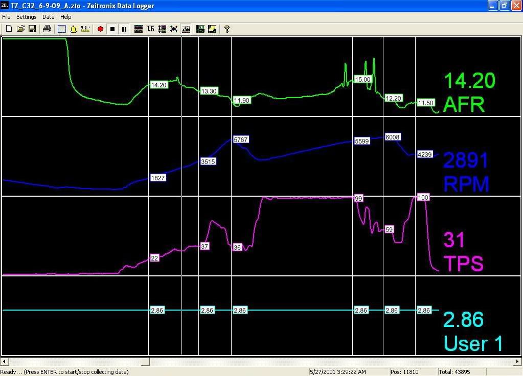
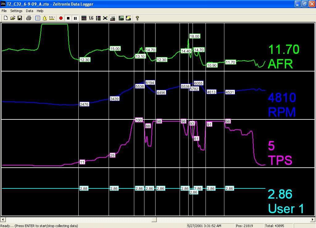
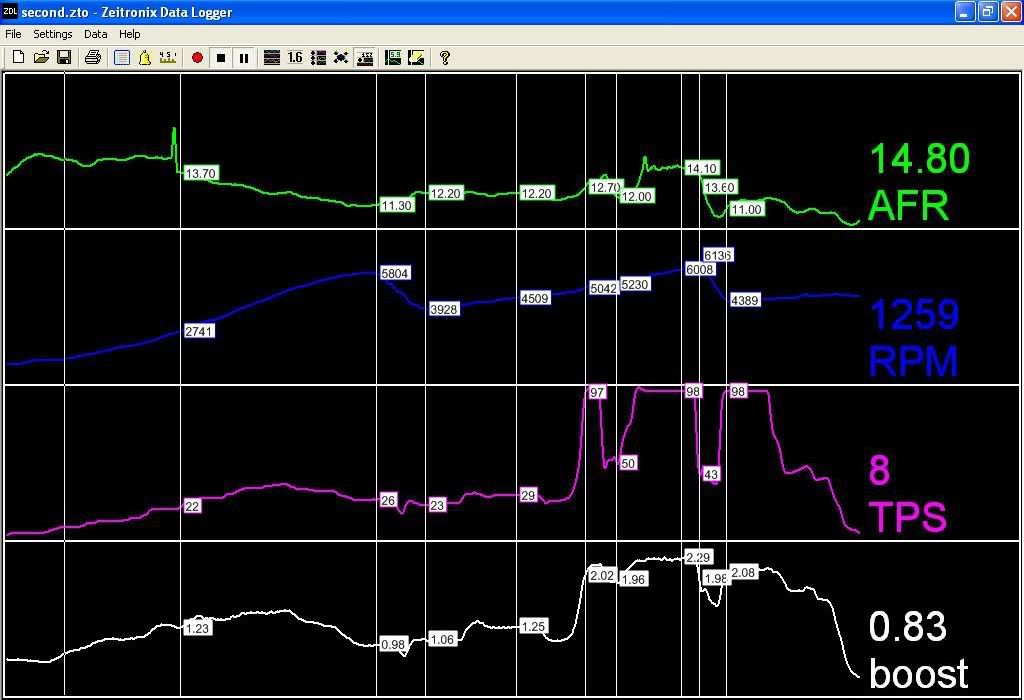
Ok weather finally dropped to 68 and I was able to data log. Here is the before and after AFRs for 1st to 3rd runs. The first two pics are with the older LET tune showing the high AFRs. Ignore the boost, I wasnt monitoring for that then. The last pic is with the newer LET tune, boost is being monitored. Finally a year later, and AFRs look much better and load limit issue is gone.
LET Tune w/185 Pulley and SL55 Intake/ITG filters
C3P Heat Exchanger for cooling
Old Tune 1st Run
Old Tune 2nd Run
New Tune
LET Tune w/185 Pulley and SL55 Intake/ITG filters
C3P Heat Exchanger for cooling
Old Tune 1st Run
Old Tune 2nd Run
New Tune
Super Member
Joined: Jul 2006
Posts: 925
Likes: 2
From: Maine
Not an AMG :(
This is a great addition to monitor the safety of modified motors.
Out of curiosity, what's your take on the high AFR at rpms higher than 5300?
The AFRs look great below 5300.
I'm assuming you're in 3rd gear at that stage and the AFRs climb rather quickly above 5300/5400 rpm up to about 6000 rpm.
After that, the AFR drops as you take the foot off the accelerator!
Is there anything that can be done (tuning-wise) about this critical rpm range in terms of decreasing the AFR? - ultimately the length of time that you spend in the 5300 - 6000 rpm range may be an important determinant in whether extra tuning is warranted.
MBWorld Fanatic!
Joined: Jun 2007
Posts: 2,949
Likes: 0
From: Philadelphia, PA
2008 A8L, 2002 996TT X50, 2009 X5
Thread Starter
Senior Member
Joined: May 2008
Posts: 251
Likes: 1
From: Aberdeen, MD
CLA

Thread Starter
Senior Member
Joined: May 2008
Posts: 251
Likes: 1
From: Aberdeen, MD
CLA
Hey boohooramblers,
I'm glad I can contribute back to the forum. My hope is that more folks will start to monitor the AFRs so we can compare results and have more granular & safer tunes. Apparently not every C32 is built the same.. there were only 4 people with tunes that I know of that had similar load limit issues, 2 of which are overseas. Maybe it has to do with the production date.. but Jerry had to do some investigation to figure out what was happening.
Unfortunately I ran out of road before I could wind out all of third... I think I need to take her to the track and just let her fly. But yes, I'm coming out of 3rd and the AFR returns to 14.7 after I let off the accelerator.
I will probably gather some more data before I warrant a re-tune but I think am running much safer now than before. That was my main concern. Now I can start to focus on what areas can be richer to get more power.
If anyone wants to see the full .zto file I can post it up for dl. You can dl the
Zeitronix software for free from their website. PM me if your interested.
I'm glad I can contribute back to the forum. My hope is that more folks will start to monitor the AFRs so we can compare results and have more granular & safer tunes. Apparently not every C32 is built the same.. there were only 4 people with tunes that I know of that had similar load limit issues, 2 of which are overseas. Maybe it has to do with the production date..
but Jerry had to do some investigation to figure out what was happening.Unfortunately I ran out of road before I could wind out all of third... I think I need to take her to the track and just let her fly. But yes, I'm coming out of 3rd and the AFR returns to 14.7 after I let off the accelerator.
I will probably gather some more data before I warrant a re-tune but I think am running much safer now than before. That was my main concern. Now I can start to focus on what areas can be richer to get more power.
If anyone wants to see the full .zto file I can post it up for dl. You can dl the
Zeitronix software for free from their website. PM me if your interested.
Great to see this being documented razormb!!
This is a great addition to monitor the safety of modified motors.
Out of curiosity, what's your take on the high AFR at rpms higher than 5300?
The AFRs look great below 5300.
I'm assuming you're in 3rd gear at that stage and the AFRs climb rather quickly above 5300/5400 rpm up to about 6000 rpm.
After that, the AFR drops as you take the foot off the accelerator!
Is there anything that can be done (tuning-wise) about this critical rpm range in terms of decreasing the AFR? - ultimately the length of time that you spend in the 5300 - 6000 rpm range may be an important determinant in whether extra tuning is warranted.
MBworld Guru


Joined: Apr 2002
Posts: 22,058
Likes: 18
From: Diamond Bar, CA
W206 PHEV AMG
 I thought it could be BAR reading, but it seems odd.
MBWorld Fanatic!
Joined: Mar 2004
Posts: 2,073
Likes: 27
From: North NJ
2002 C32 AMG, 2013 GLK 350/4, 2015 E63S AMG Wagon
MBWorld Fanatic!
Joined: Dec 2007
Posts: 5,034
Likes: 6
From: Corona, CA
03 g35 coupe...........02 c32 Sold
Thread Starter
Senior Member
Joined: May 2008
Posts: 251
Likes: 1
From: Aberdeen, MD
CLA
MBWorld Fanatic!
Joined: May 2004
Posts: 1,482
Likes: 4
From: Portugal
'13 E500 Coupe AMG// '17 E350d // '24 E53 AMG
Hello all,
I've just installed a zeitronix ZT-2 with O2 sensor and boost sensor.
I also connected the TPS to the ZT-2 that is working ok and also connected the rpm on the ECU but I think that it's not reading ok.
I connected to the crank sensor but the rpm at idle are way to high.
Theres's any software correction that's needed? how can I calculate the value for correcting the rpm?
I allready tried the "6" as six cylinder that is my engine but rpm turns down to 20000rpm or so, if enter "1" the rpm is 800000rpm or so, but if i enter 110 the real value of rpm is closer to the zt-2 reading!
What should I enter on the zeitronix software?


