When you click on links to various merchants on this site and make a purchase, this can result in this site earning a commission. Affiliate programs and affiliations include, but are not limited to, the eBay Partner Network.
Mechanical Boost Gauge Installation in Mercedes C43 coupe
This thread is to document and discuss my effort to install a mechanical boost gauge in the c43 AMG Coupe.
Why do it: Even though we have a "boost gauge" on the dash, it doesn't really show actual boost, but rather an electronic representation of when the car is in full or partial boost. I wanted something more accurate.
Challenge: As of today no vendor has installed or is offering a boost gauge for ours cars. Despite having vacuum diagram I am still unsure as to which line to "T" tap into for most accurate boost.
Plan: P3 makes a beautiful unit for the CLA45 which connects to OBDII and a gauge which fits in the center vent. I plan on removing the center vent and mocking up a gauge which will fit, similar fashion to the P3 gauge. I will then run a line to the vacuum setup for boost.
Step 1: Dash has been taken apart and the vent has been removed. After carefully looking at vent I was able to completely disassemble the out and inner vent and trim rings. I plan on mounting the new Boost Gauge which I had made from Speedhut in either the inner (movable vent) or outer ring, fully removing the inner (movable) system. I will pass the power/ground and vacuum line through the rear of the vent and routed behind the dash into the engine bay. I will then block off the vent so no air can reach the rear of the boost gauge.
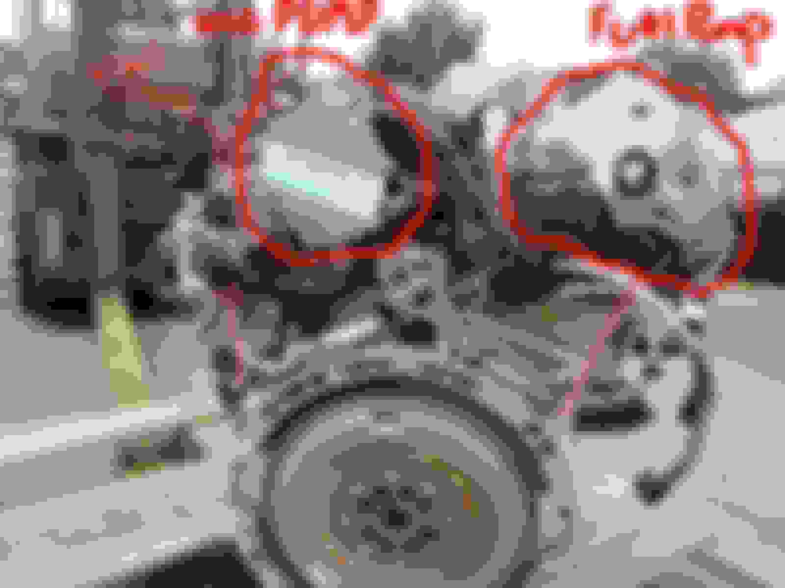
From what I can gather the vacuum system starts at the vacuum pump located on drivers rear side of the engine. A line comes off the top of the vacuum pump and runs under the ECU Tray and wiring above the manifold and comes out on the passenger side/front of the motor, running down the front and connecting to the boost controller/vacuum regulator on front. Then another vacuum line runs from boost controller/vacuum regulator to both external waste gates attached to the turbos. Diagram below shows vacuum pump and lines but does not sow the boost controller/pressure transducer.
Typically when installing a boost gauge You want to get vacuum pressure from the manifold-right? However in this setup vacuum is coming from the vacuum pump, and I cant find a Vacuum line that is coming out of the manifold. So, do I put my "T" tap for boost gauge into the vacuum line coming from the vacuum pump in rear of engine, or the vacuum line which runs in between both waste gates?
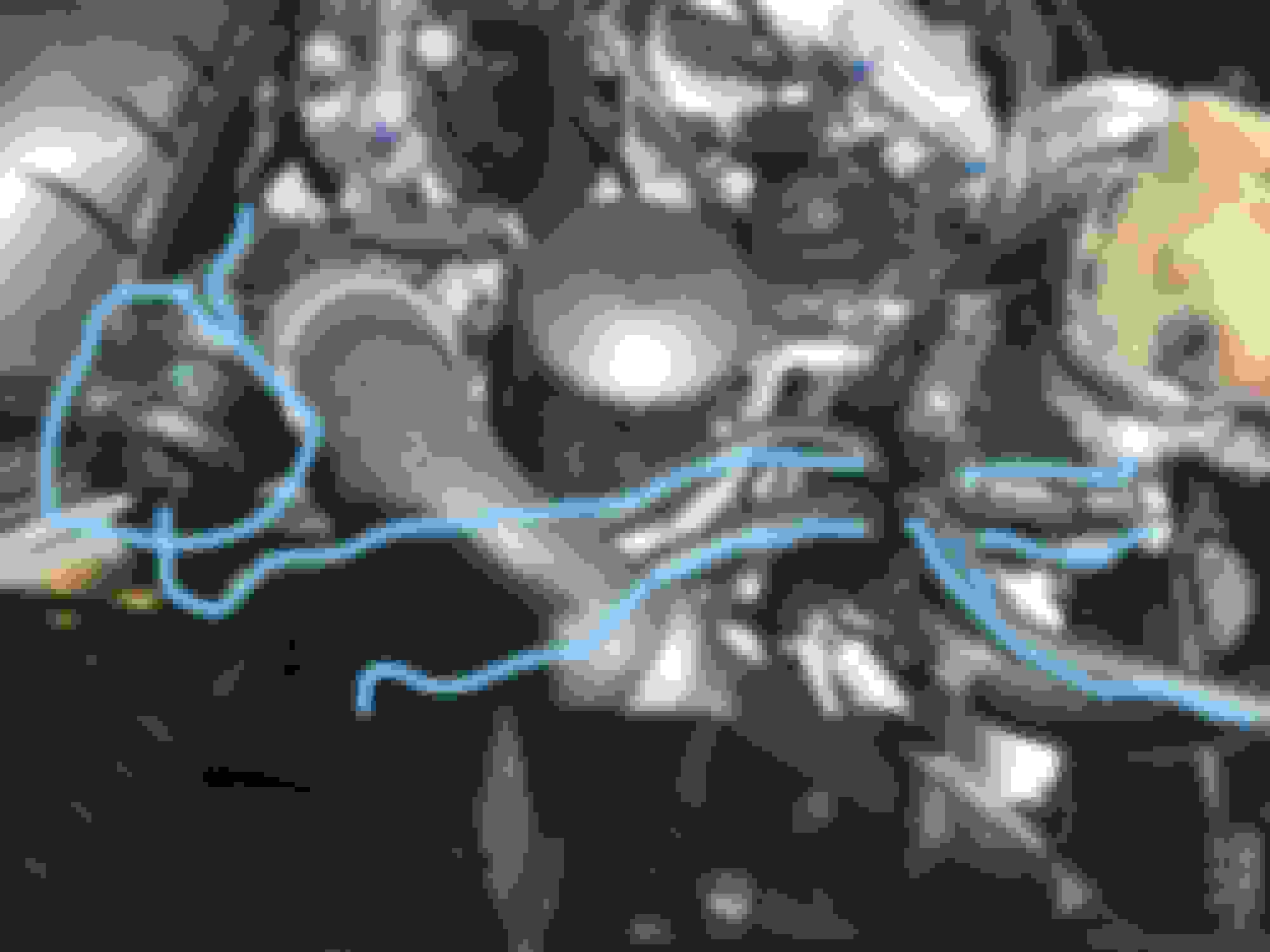
Now let's complicate this further...there is some sort of line which is tapped into the front of the manifold pictured below. Per the diagram this is a "vent line" which runs out of the front of the manifold and splits to another line which runs into the motor and i cant follow and then splits off to another valve which runs to the front of one turbo and into the fuel system purge valve. I'm assuming this wouldn't be used for boost gauge vacuum?
After further research I don't think the vacuum lines coming from the waste gates or the vacuum pump are good candidates to get boost and vacuum since they aren't reading from the manifold. I'm leaning towards tapping the boost gauge vacuum line into two of two lines which come off the front of the manifold charge pipe, right after the Throttle Body. The first line goes into some type of splitter with a senor on top, the second line goes to the fuel purge valve. Can anyone comment on this approach?
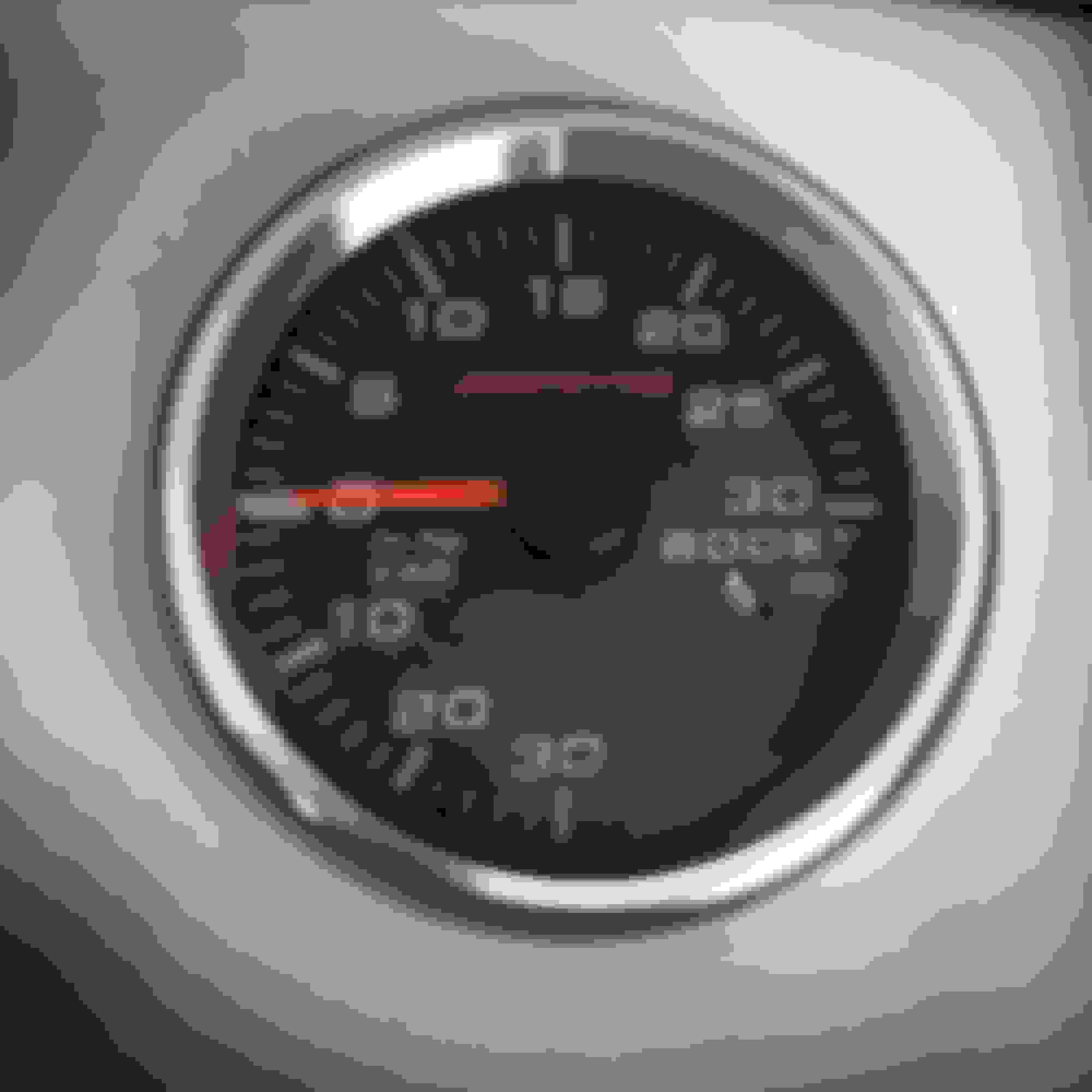
Custom Gauge from Speedhut showed up. Great quality and craftsmanship. I made a custom spacer and got it to fit in the original vent housing by taking the vent apart and removing the vent fins. I blocked off the rear of the vent adn added heat reflecting tape to protect the rear of the gauge and wires. I ran the wires down the back of the center console, heat wrapped and following the original electrical lines of various components behind the dash. I tapped into ignition power, lights power and ground at the cigarette lighter harness. I was trying to make this look as if it came stock and I'm pretty happy with how it turned out. Now to figure out where to get boost an vaccum from and find a convenient hole in firewall to route vacuum tube into the engine bay.
I ran the boost gauge sensor from behind the dash and through a gromet on the drivers side of the engine bay. Then routed under rain tray trim and found a really nice spot to mount the pressure gauge. Now I just need to run the vacuum line.
That's really cool! Once this is all said and done, try to post a video with the digital display on the screen. I'd like to see the two guages in action...! Hurry up with that vacuum line... what's the hold up!?! Hahaha!
Are the bypass/diverter valves on the turbos purely electronically controlled, or do they have a vac reference line hooked up to them?
These would be the controllers that are bolted into the compressor housing assuming the C43 has an internal DV vs. an external DV.
If it has a vacuum tap, I would use this, however this will only give you a single turbo's pressure vs. the other, though I'd kind of expect that given each turbo is producing an independent volume of air purely based on it's exhaust bank's air flow..
Sorry for long delay in posting updates. The boost gauge is completed and working. There are no vacuum lines coming off the manifold. There are only two places you can get boost and vacuum from the manifold: 1. is from the pressure sensor on top of the manifold. The issue with this is that the sensor fills the hole and no company has made a boost tape which allows you to still use the sensor and a nipple for the boost /vac line. 2. the second spot is right in front of the manifold- there is a hole which is plugged by a two disc shaped valve. The valve is a one way valve which allows airflow/fluid into the manifold but not out. After the valve there is one line that runs under the manifold to the oil seperator (this is a vent line). The second line runs to the fuel purge valve. I decided this is where I would tap for boost (before the valve), since I did not want to drill into the manifold to tap for boost gauge.
After hours of trips to auto parts stores and several brass fittings-I finally mocked up an adapter which would allow me to use the factory one way disc valves and add a boost tap. I ended up using brass fittings and epoxy to make it all work. Pictures below:
From your description, it's hard to see how you would be getting actual reference boost pressures vs. artificial pressures caused by a vac pump or bleed-off crank pressure leading to the "disc valve" you described.
What're you reading at idle for vac and what boost pressure under full/heavy load?
I'm not using a vacuum line. I'm getting boost and vacuum straight from the manifold. If you look at the adaptor I made, it plugs into the manifold and then one side goes to boost line nipple and other side goes to the one way valve which then splits to oil seperator and fuel purge valves. These lines don't let boost/vacuum out only air in to the manifold. I'm getting 15 lbs of boost right now at WOT and vacuum around 20 inches of mercury at rest, which is what you want.
I'm not using a vacuum line. I'm getting boost and vacuum straight from the manifold. If you look at the adaptor I made, it plugs into the manifold and then one side goes to boost line nipple and other side goes to the one way valve which then splits to oil seperator and fuel purge valves. These lines don't let boost/vacuum out only air in to the manifold. I'm getting 15 lbs of boost right now at WOT and vacuum around 20 inches of mercury at rest, which is what you want.
By vac I didn't mean vacuum line - I meant vac you'd see at idle
It's really hard to tell from your image what's oriented where. It looked like you had your setup post-PCV on the crank side/oil separator side vs. the manifold side which is why I was curious. Directly referencing manifold pressure in your adapter makes perfect sense.. awesome!
Sorry for long delay in posting updates. The boost gauge is completed and working. There are no vacuum lines coming off the manifold. There are only two places you can get boost and vacuum from the manifold: 1. is from the pressure sensor on top of the manifold. The issue with this is that the sensor fills the hole and no company has made a boost tape which allows you to still use the sensor and a nipple for the boost /vac line. 2. the second spot is right in front of the manifold- there is a hole which is plugged by a two disc shaped valve. The valve is a one way valve which allows airflow/fluid into the manifold but not out. After the valve there is one line that runs under the manifold to the oil seperator (this is a vent line). The second line runs to the fuel purge valve. I decided this is where I would tap for boost (before the valve), since I did not want to drill into the manifold to tap for boost gauge.
After hours of trips to auto parts stores and several brass fittings-I finally mocked up an adapter which would allow me to use the factory one way disc valves and add a boost tap. I ended up using brass fittings and epoxy to make it all work. Pictures below:
I haven't had my second cup of coffee yet, so I'm conflicted about something. First off- your gauge install looks great. Good work. I use a boost gauge that pulls data via OBD and it appears to work well and accurately... what led you to go the way you did- what's the deficiency with the OBD vac/boost info?
My reasoning is that a mechanical boost gauge from the manifold would confirm what the OBD is reading. I feel like a mechanical gauge would be the most accurate.
Mercedes SLR McLaren 722 S Is Extremely Rare Example Modified by McLaren
Slideshow: A one-of-one U.S.-spec Mercedes-Benz SLR McLaren Roadster became even rarer after a factory-backed transformation at McLaren's headquarters.