
ABC Tandem Pump Rebuild Process (Not Recommended)


Thread Starter
Super Member


Joined: Dec 2007
Posts: 980
Likes: 224
2005 S500 Designo
ABC Tandem Pump Rebuild Process (Not Recommended)
I just rebuild the ABC Tandem Pump for the M112 V6 and M113 V8 engines, but the process will be similar for the M275 and other engines.
Introduction
Mercedes calls these pumps "Non-Rebuildable" by normal mechanics, and after having gone through this process I kind of agree with them. This is NOT an easy rebuild, because it is FRAUGHT WITH PITFALLS that need to be avoided. Just because you can go through the process, does not mean you will then end up with an ABC pump that will last you the 100k+ miles necessary. Even as I write this, I am not 100% confident in my work. Additionally, the process for removal and replacement from the vehicle is involved enough that the potential savings IMO simply aren't worth it. You are better off buying a rebuilt or brand new pump from Mercedes-Benz.
This is the second time I am doing this rebuild, the first time I fell into one of the many pitfalls and so the pump isn't lasting as it should, and is additionally putting strain on the rest of the ABC hydraulic system, which is really not good. There are no torque values or any sort of manual, you will be flying by the seat of your pants. Don't take anything I say as gospel or instruction. It is IMPERATIVE you work in an organized and diligent manner, keeping track of things as you go.You have been warned.
That said, if you're capable of all the above, it shouldn't be so bad.
The reason I'm writing this post is because right now I only see one other resources available, and let's just say it's not the best:
This is not going to be an exhaustive post, DIY, or Instruction, but should serve as some guide for anyone that wants to rebuild their ABC pump.
I'm going to assume you have some familiarity with the ABC system and how it works, if not click here.
Supplies:
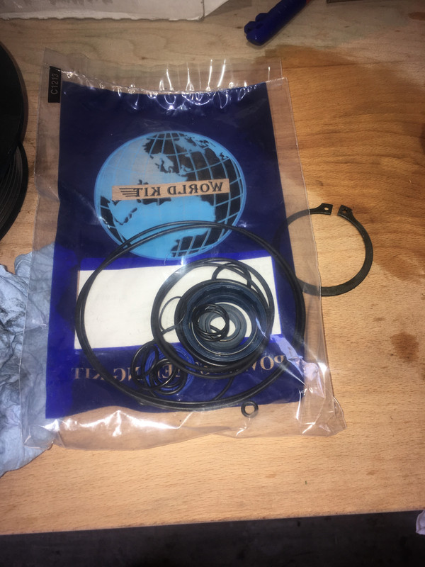
ABC Rebuild Kit offered by invasion auto products (no affiliation). They offer two kits, it's up to you to source the correct one:
Seal Kit 1
or
Seal Kit 2
The kit is nothing more than a bag with all the o-rings and seals, nothing is labeled, their tech support is close to non-existant, there are additional nylon spacers in the pump that are not included in the kit, and I'm not convinced they're supplying the correct type of o-rings. Again, I do NOT recommend doing this process.
I believe for the M113 V8 I used the Seal Kit 1.
https://postimg.cc/WhfGwk8J
About half a cup (125mL) of CHF11S
Hydraulic Sealant (I recommend Loctite 545 but it's not what I used). Note the specific instructions for Loctite 545
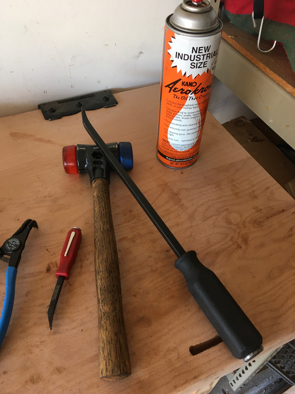
Some sort of penetrant, I recommend Kroil
Optional: Replacement springs (good to have on hand if you notice yours are broken)
Tools:
In addition to all the basic tools required to work on Mercedes, you're going to need the following:
A bench vise or press for installing bearings and the cover
An impact driver
Some way of cleaning sealant/adhesive from nut/bolt threads (I used a bench grinder with a wire wheel and some picks, you can probably get away with picks and a lot of patience)
Picks (the harbor freight ones are fine)
A digital caliper for measuring and differentiating the o-rings
Compressed Air
A clean work area
You're going to want to take pictures with your phone
Lots of shop towels/lint free towels
Snap Ring Pliers
Pullers/Puller to get the main pump off the shaft
Paint can openers (the ones you get for like $1 at the paint section in the hardware store)
CHF11S applicator bottle/pump thingy
Process:
Before you even do anything on the pump, you're going to need to take it to a machine shop to have the front metal pulley mount pressed+hammered off of the pump shaft.
This requires a press that allows the operator to additionally apply hammer blows to separate. It's in there tight.
You're going to want to note the orientation of the pulley on the shaft, because the pulley mount is not symmetrical and must be re-mounted appropriately onto the shaft. You will have one shot at that (see note at the end of the post).
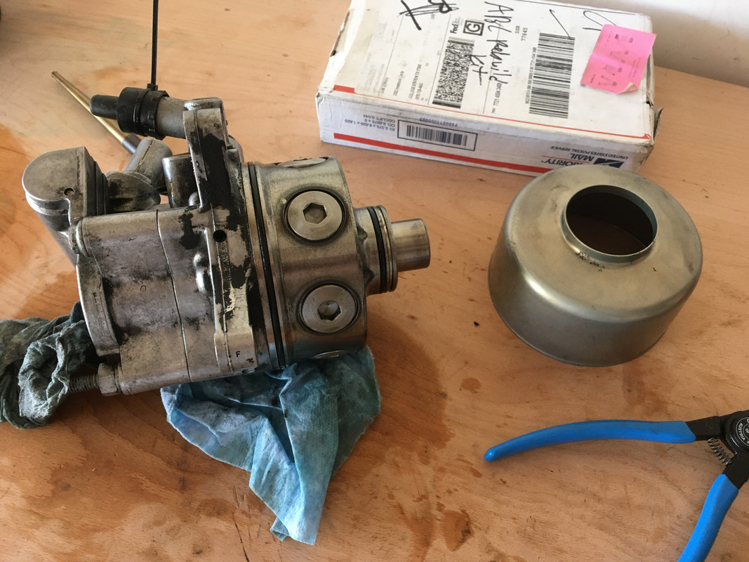
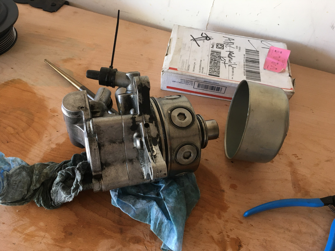
Once you have your pulley mount off your pump shaft, you're going to begin by removing the cover. This is achieved by first removing the snap-ring plier off the pump assembly at the front, placing the pump on the shaft, and with a pry-bar and hammer tapping (pretty hard) around the perimeter of the cover until it slides off. Penetrating oil helps.
https://postimg.cc/7GM13ttx
https://postimg.cc/rDK9BJsJ
https://postimg.cc/FkryDbw0
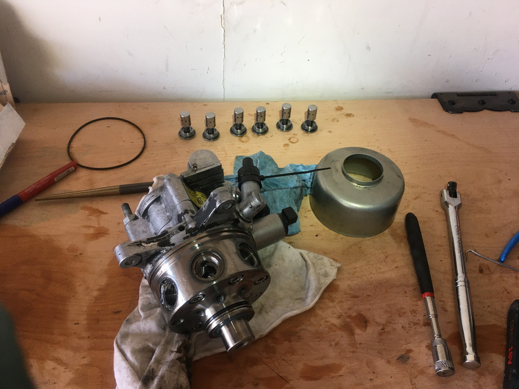
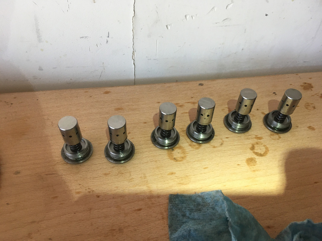
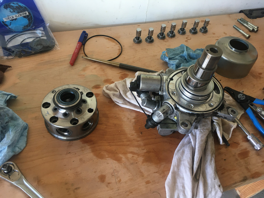
Next you're going to want to remove seven caps holding the springs and cylinders against the eccentric shaft of the pump. This is the heart of the unit ABC pump, but I'm not going to claim I know exactly how it works. You're going to need a 10mm hex socket and and impact wrench/driver. Don't attempt it by hand. The caps threads are held in with some sort of adhesive/sealant that you're going to have to painstakingly remove prior to re-installation. I've seen reports that on some pumps these springs are broken. You can buy replacements online. I got some but didn't use them, because I don't trust the specifications match exactly, and none of mine were broken. I'll post what I have in a reply to this thread.
https://postimg.cc/yWsy1BWW
https://postimg.cc/LhDBh7ZD
https://postimg.cc/vcm7nzrs
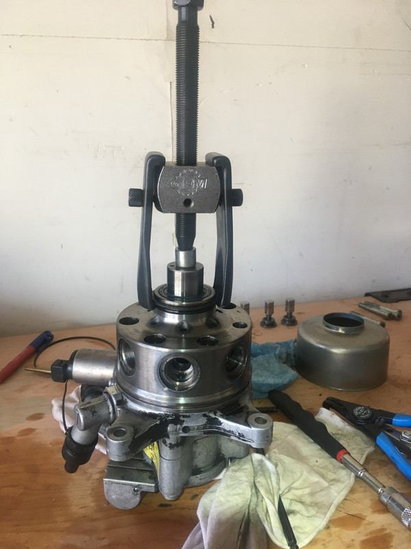
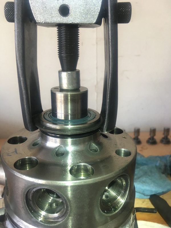
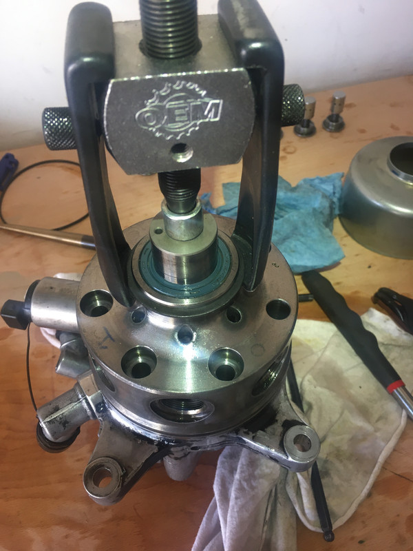
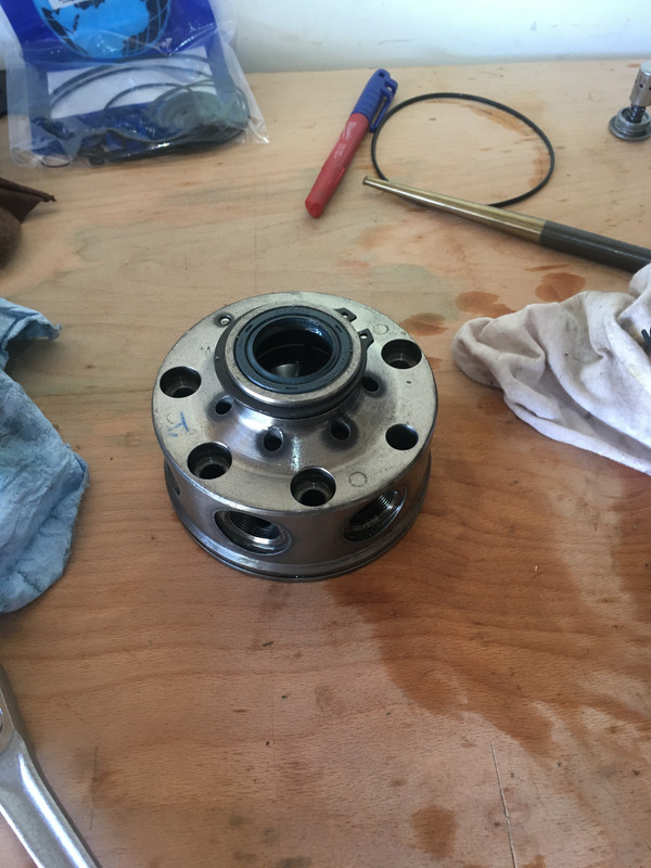
Next you want to remove the heart of the pump assembly. First remove the four hex bolts holding the pump assembly to the pump housing (6mm I think), then you'll need a puller. It's not on particularly tight, but I don't see an elegant way to get it off w/o a puller. In a pinch something could probably be figured out, but with a good chance of screwing something up. I had to re-install the snap-ring so my puller had something to bite against and pull.
https://postimg.cc/DSJqjwpp
https://postimg.cc/Hrqbf1fY
https://postimg.cc/1gDDSYQp
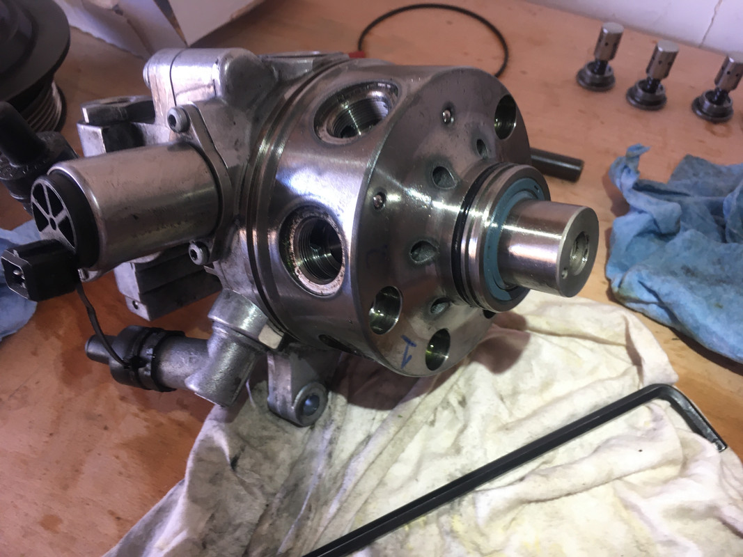
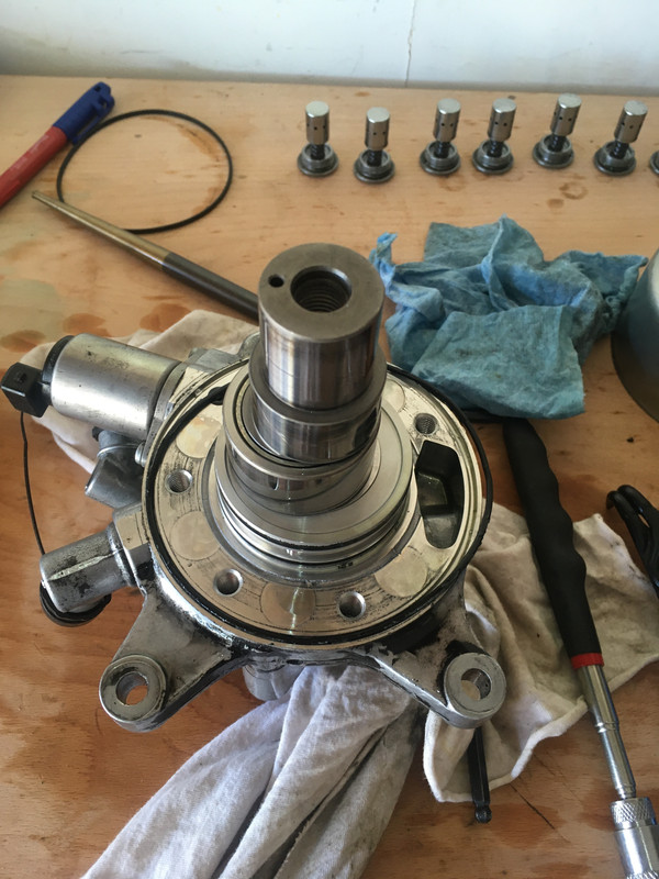
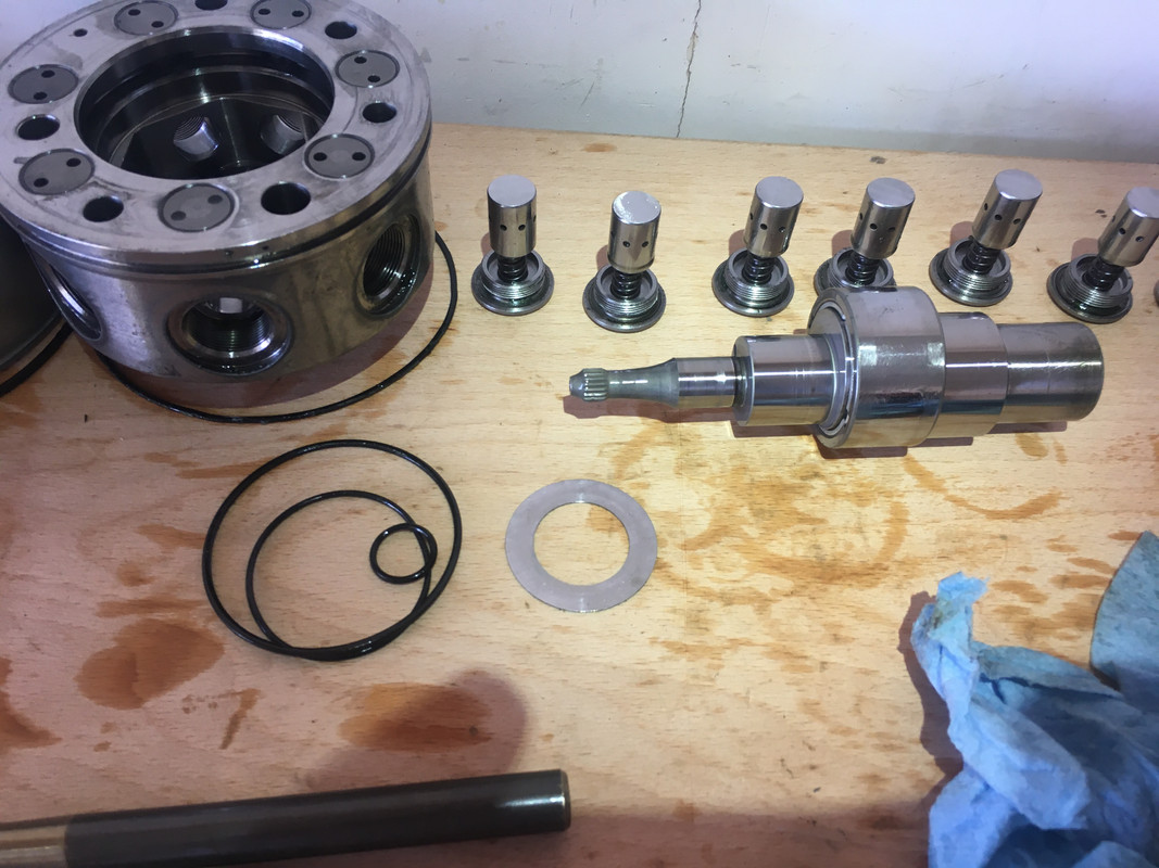
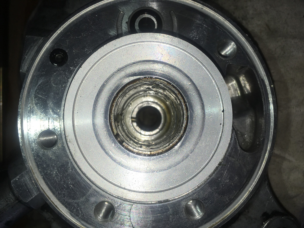
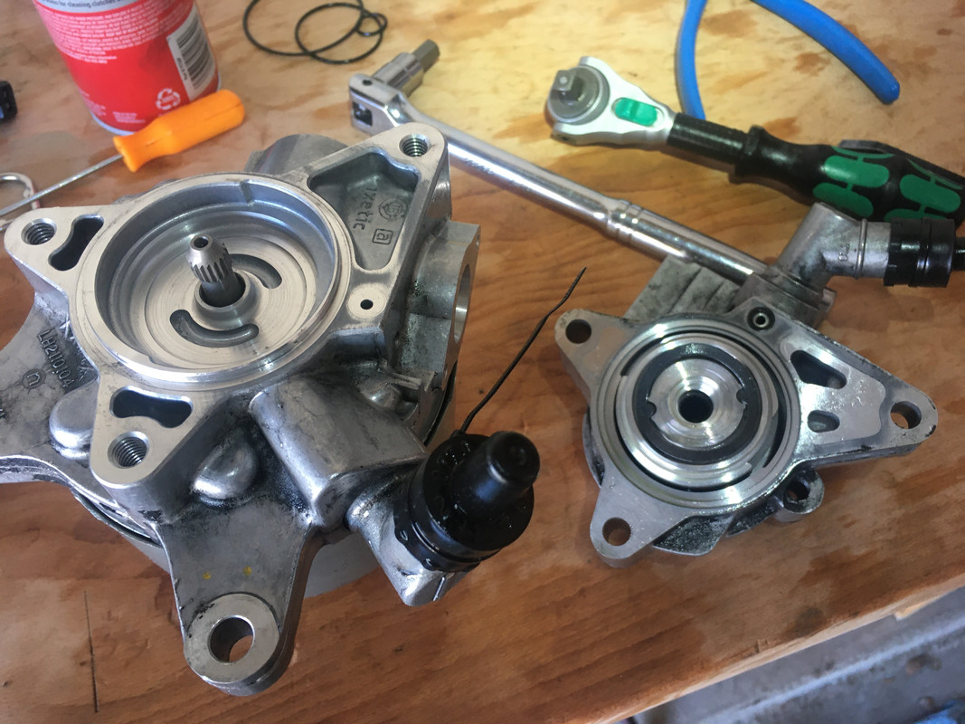
Now you have your first view of the inner workings of the pump: you have an eccentric shaft that rotates around and pushes the seven cylinders that go on to built pressure in the ABC system. The inherent imbalance in the shaft is made up by a weight and cutout in the pulley. The orientation of the pulley is determined by the heat-press-fit pulley mount at the end of the shaft. Getting this right during installation is imperative. There are additional cylinders or something in the main pump. I have no clue how it works beyond what I've described. With the main ABC pump out, you can inspect the shaft that will tell you if this unit is beyond salvage. If the pump fails from running dry, it's the cylinders pressing against the eccentric shaft that causes friction that eats it apart. Additionally the eccentric shaft has a sleaved/bushing thing with a channel of oil feeding it in the middle. I imagine that would get fried as well. This is the soonest that it can be obvious whether or not your pump is beyond repair.
https://postimg.cc/ygBc8X12
https://postimg.cc/0MfmMMrj
https://postimg.cc/2LSW4kBw
https://postimg.cc/grz39DBZ

https://postimg.cc/vD0fGVpS
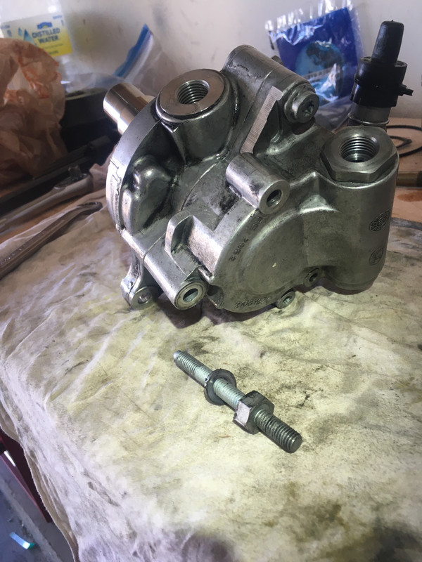
Now you can remove the rear power steering pump. There are two torx bolts of different sizes (T40 I believe) and a nut shaft bolt thing. I tried to document their orientation in the following pictures:
https://postimg.cc/D8ms0zhf
https://postimg.cc/0b3Swq5Y
https://postimg.cc/PCwwbFNB
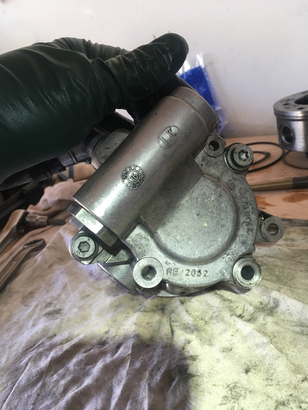
There are three o-rings between the power steering pump and the ABC pump housing. I removed these first lest they fall out on their own and I forget to replace them. These will be replaced last, so put them aside but keep them organized. The Power Steering pump has a Luk part # that I believe can be bought for not a bajillion dollars. If you're having power steering troubles, you might want to investigate buying this part. There is additionally a spring washer thing between the power steering unit and the ABC pump housing. It has two little wing guys that slot into the main PS pump so it doesn't move around. Make a note of its orientation, it'll be obvious once you look at it/see it.
https://postimg.cc/p9MnsYFy
https://postimg.cc/DWQ4HJr6
https://postimg.cc/V0vSJK3Z
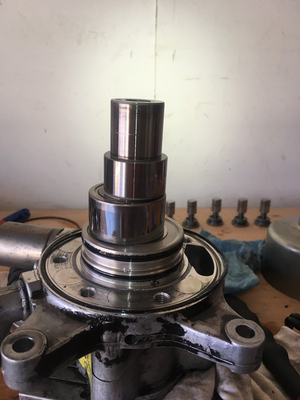
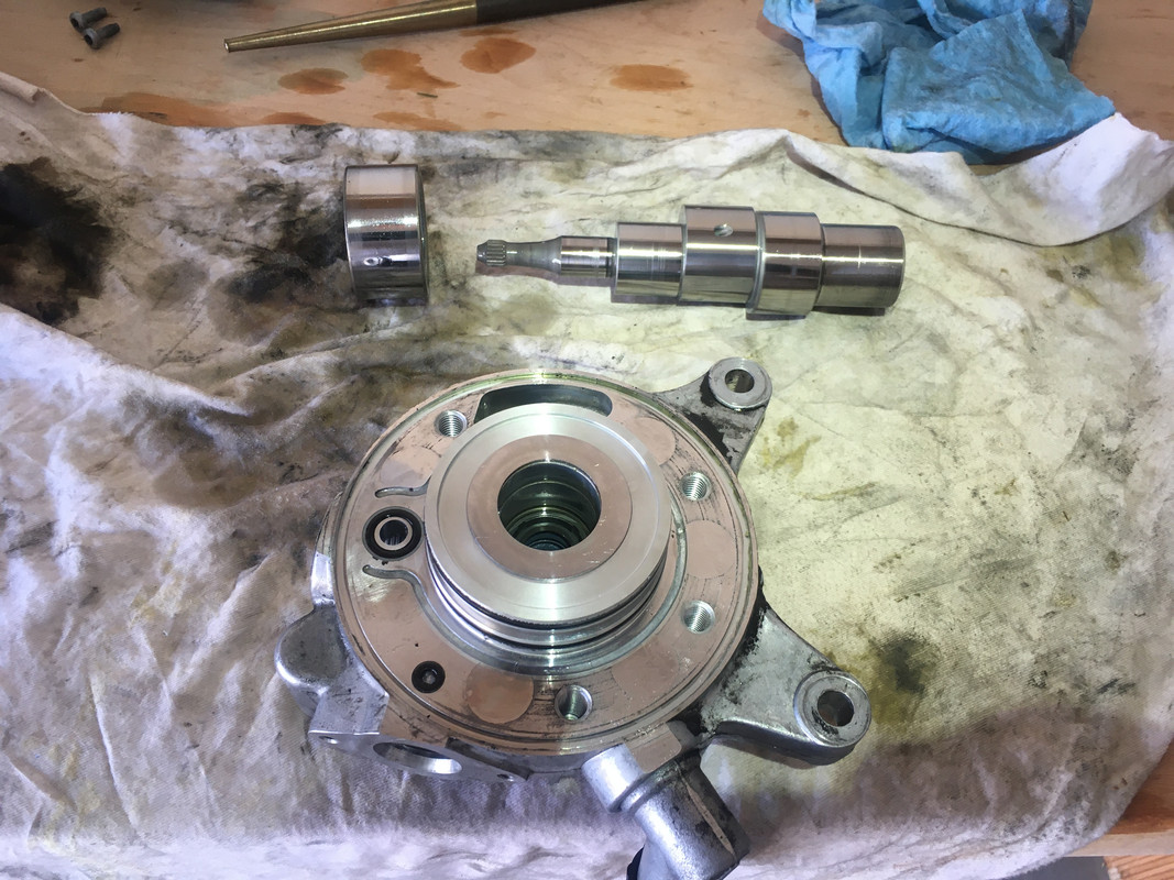
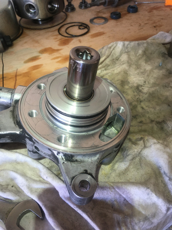
Now you can remove the shaft of the pump. There is a spacer washer between the shaft and the main ABC pump housing.
https://postimg.cc/sQVGrjKr
https://postimg.cc/9RJRX6Nq
https://postimg.cc/F1HkCK7b
https://postimg.cc/F1CdMQLM
https://postimg.cc/SJX2qtLJ
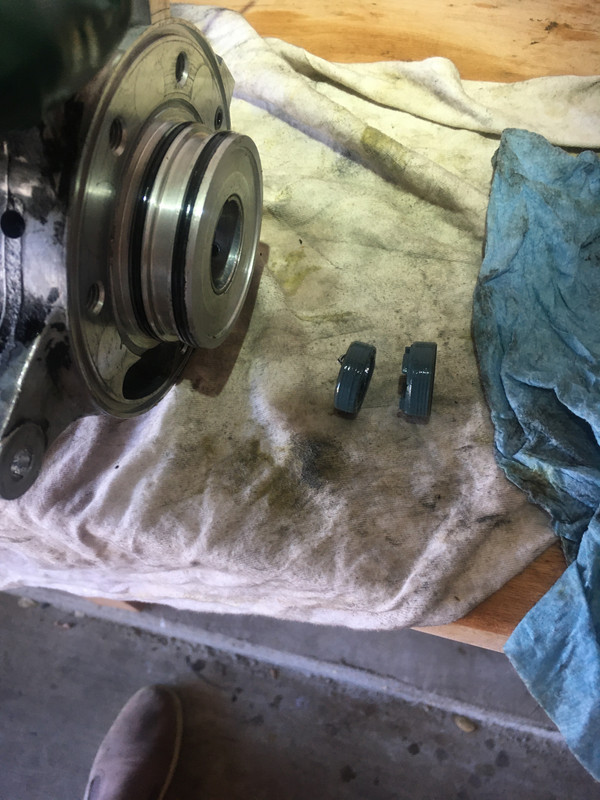
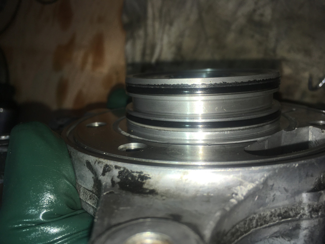
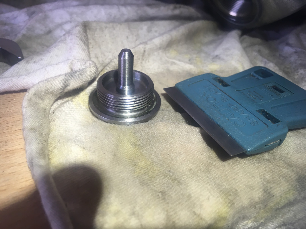
Now we can actually start replacing parts on the unit. I recommend disassembling everything first, then replacing o-rings and seals as you put the unit back together. It's easy to lose track. First up are the two seals separating the Suspension pump from the Power Steering pump. For this the paint can opener was the perfect tool. Take care that you DO NOT SCORE THE SEAL HOUSING. Unfortunately I managed to do so. I believe I pried the top seal out from the ABC side, and pushed the bottom seal out from the PS side with the same paint can opener and a hammer. You'll have to figure this one out for yourself. I don't recommend a pick. The seals spoon up against one another with one being a male seal and the other a female seal. They're installed in the mating position. I have no better way to describe this.
https://postimg.cc/jLGWjQvv
https://postimg.cc/BjHjPLV3
https://postimg.cc/KKbRPG6M
https://postimg.cc/GBj9q0RS
https://postimg.cc/gXkj7Mkc
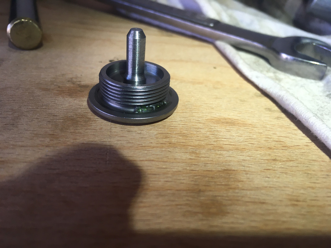
The seals will be installed together, otherwise there's no way to keep them in their mating position. Put the two seals together and install using an appropriate socket for installing seals. If you've never installed seals before, look up how to do this separately. I found a Craftsman 11/16" socket fit perfectly on the perimeter of the larger (ABC-side) seal, and I used my bench vise to push it in cleanly. I do NOT recommend using a hammer and trying to tap it in straight. I used a tiny amount of grease, and put the seals in the freezer prior to installation. Obviously you should be cleaning up as you go.
https://postimg.cc/9R80HGrd
I don't have pictures; install the big seal on the main ABC pump unit for the shaft. Again I used a bench vise and a socket.
Now things should go pretty fast. Clean everything using shop towels/lint free cloths/compressed air. You can replace the o-rings on the ABC pump. It's very obvious on mine that hydraulic fluid had started slipping past. There are two nylon spacers on the larger o-rings that were not included in the kit. They are oriented OUTWARDS from the center. There are additional nylon spacers around one of the smaller o-rings on the ABC pump housing (not the smallest one). These were also not included in the kit. Use your judgement, replace the o-rings and keep track of which have been replaced and which haven't.
https://postimg.cc/D4SZv8Xt
https://postimg.cc/K4j4rsHJ
Install the shaft, don't forget the washer, and install the main pump. Take care not to **** up your newly installed seals. The kit only comes with one copy, in all likelihood the old ones were ****ed up from the removal process. If you screw this up you probably have to buy a second kit for $100. Use the four hex bolts to slip the main ABC pump onto the ABC pump housing, tightening progressively as you go. You'll feel it very obviously. I have no torque value for these. Tight but not stupid tight.
https://postimg.cc/jC1284VK
https://postimg.cc/vc6BCxMn
https://postimg.cc/zyZBNDXc
Now comes the misery of removing all the sealing compound used for the pump cylinder holder bolts. It's probably not kosher, but I used a wire wheel and a bench press. Kroil didn't dissolve the caked on crap, neither did brake parts cleaner. I also used a pick and a razor blade. This is also where I re-added hydraulic sealant. Loctite 545 is recommended by hydraulic pump rebuilders online (again, this isn't gospel) and comes with specific instructions that I heeded. I'm not sure sealant is necessary, but some thread locker for sure, lest these back their way out. Part of the challenge was cleaning the threads with brake parts cleaner, then adding CHF11S as I re-installed the cylinder w/o contaminating the threads.
https://postimg.cc/753LZv5Y
https://postimg.cc/wt9jtWN5
Now you can install the cover. A hammer is ill-advised here, but it took me some scratching my head to figure out how to do it. I tried hammering first, but it did basically ****all. Eventually I used a garbage disposal flange for a kitchen sink in conjunction with my vise to push it on. This actually worked so well, if all else fails I straight up recommend getting that (hardware store, $10 or so). Then you can re-install the snap-ring. Obviously replace the o-rings prior to reassembling. Don't push on the shaft with the vise. It doesn't take a lot of force.
https://postimg.cc/GBzhvkPW
Continued on next post
Introduction
Mercedes calls these pumps "Non-Rebuildable" by normal mechanics, and after having gone through this process I kind of agree with them. This is NOT an easy rebuild, because it is FRAUGHT WITH PITFALLS that need to be avoided. Just because you can go through the process, does not mean you will then end up with an ABC pump that will last you the 100k+ miles necessary. Even as I write this, I am not 100% confident in my work. Additionally, the process for removal and replacement from the vehicle is involved enough that the potential savings IMO simply aren't worth it. You are better off buying a rebuilt or brand new pump from Mercedes-Benz.
This is the second time I am doing this rebuild, the first time I fell into one of the many pitfalls and so the pump isn't lasting as it should, and is additionally putting strain on the rest of the ABC hydraulic system, which is really not good. There are no torque values or any sort of manual, you will be flying by the seat of your pants. Don't take anything I say as gospel or instruction. It is IMPERATIVE you work in an organized and diligent manner, keeping track of things as you go.You have been warned.
That said, if you're capable of all the above, it shouldn't be so bad.
The reason I'm writing this post is because right now I only see one other resources available, and let's just say it's not the best:
This is not going to be an exhaustive post, DIY, or Instruction, but should serve as some guide for anyone that wants to rebuild their ABC pump.
I'm going to assume you have some familiarity with the ABC system and how it works, if not click here.
Supplies:
ABC Rebuild Kit offered by invasion auto products (no affiliation). They offer two kits, it's up to you to source the correct one:
Seal Kit 1
or
Seal Kit 2
The kit is nothing more than a bag with all the o-rings and seals, nothing is labeled, their tech support is close to non-existant, there are additional nylon spacers in the pump that are not included in the kit, and I'm not convinced they're supplying the correct type of o-rings. Again, I do NOT recommend doing this process.
I believe for the M113 V8 I used the Seal Kit 1.
https://postimg.cc/WhfGwk8J
About half a cup (125mL) of CHF11S
Hydraulic Sealant (I recommend Loctite 545 but it's not what I used). Note the specific instructions for Loctite 545
Some sort of penetrant, I recommend Kroil
Optional: Replacement springs (good to have on hand if you notice yours are broken)
Tools:
In addition to all the basic tools required to work on Mercedes, you're going to need the following:
A bench vise or press for installing bearings and the cover
An impact driver
Some way of cleaning sealant/adhesive from nut/bolt threads (I used a bench grinder with a wire wheel and some picks, you can probably get away with picks and a lot of patience)
Picks (the harbor freight ones are fine)
A digital caliper for measuring and differentiating the o-rings
Compressed Air
A clean work area
You're going to want to take pictures with your phone
Lots of shop towels/lint free towels
Snap Ring Pliers
Pullers/Puller to get the main pump off the shaft
Paint can openers (the ones you get for like $1 at the paint section in the hardware store)
CHF11S applicator bottle/pump thingy
Process:
Before you even do anything on the pump, you're going to need to take it to a machine shop to have the front metal pulley mount pressed+hammered off of the pump shaft.
This requires a press that allows the operator to additionally apply hammer blows to separate. It's in there tight.
You're going to want to note the orientation of the pulley on the shaft, because the pulley mount is not symmetrical and must be re-mounted appropriately onto the shaft. You will have one shot at that (see note at the end of the post).
Once you have your pulley mount off your pump shaft, you're going to begin by removing the cover. This is achieved by first removing the snap-ring plier off the pump assembly at the front, placing the pump on the shaft, and with a pry-bar and hammer tapping (pretty hard) around the perimeter of the cover until it slides off. Penetrating oil helps.
https://postimg.cc/7GM13ttx
https://postimg.cc/rDK9BJsJ
https://postimg.cc/FkryDbw0
Next you're going to want to remove seven caps holding the springs and cylinders against the eccentric shaft of the pump. This is the heart of the unit ABC pump, but I'm not going to claim I know exactly how it works. You're going to need a 10mm hex socket and and impact wrench/driver. Don't attempt it by hand. The caps threads are held in with some sort of adhesive/sealant that you're going to have to painstakingly remove prior to re-installation. I've seen reports that on some pumps these springs are broken. You can buy replacements online. I got some but didn't use them, because I don't trust the specifications match exactly, and none of mine were broken. I'll post what I have in a reply to this thread.
https://postimg.cc/yWsy1BWW
https://postimg.cc/LhDBh7ZD
https://postimg.cc/vcm7nzrs
Next you want to remove the heart of the pump assembly. First remove the four hex bolts holding the pump assembly to the pump housing (6mm I think), then you'll need a puller. It's not on particularly tight, but I don't see an elegant way to get it off w/o a puller. In a pinch something could probably be figured out, but with a good chance of screwing something up. I had to re-install the snap-ring so my puller had something to bite against and pull.
https://postimg.cc/DSJqjwpp
https://postimg.cc/Hrqbf1fY
https://postimg.cc/1gDDSYQp
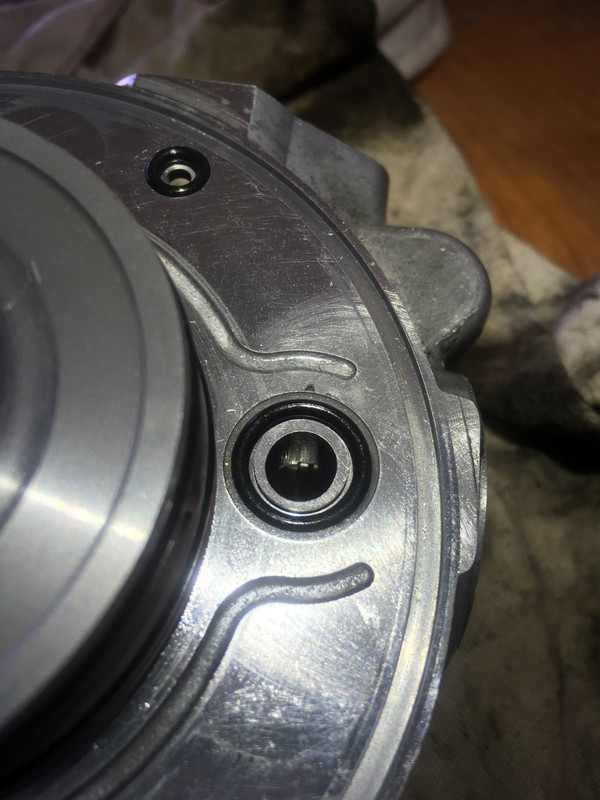
Now you have your first view of the inner workings of the pump: you have an eccentric shaft that rotates around and pushes the seven cylinders that go on to built pressure in the ABC system. The inherent imbalance in the shaft is made up by a weight and cutout in the pulley. The orientation of the pulley is determined by the heat-press-fit pulley mount at the end of the shaft. Getting this right during installation is imperative. There are additional cylinders or something in the main pump. I have no clue how it works beyond what I've described. With the main ABC pump out, you can inspect the shaft that will tell you if this unit is beyond salvage. If the pump fails from running dry, it's the cylinders pressing against the eccentric shaft that causes friction that eats it apart. Additionally the eccentric shaft has a sleaved/bushing thing with a channel of oil feeding it in the middle. I imagine that would get fried as well. This is the soonest that it can be obvious whether or not your pump is beyond repair.
https://postimg.cc/ygBc8X12
https://postimg.cc/0MfmMMrj
https://postimg.cc/2LSW4kBw
https://postimg.cc/grz39DBZ
https://postimg.cc/vD0fGVpS
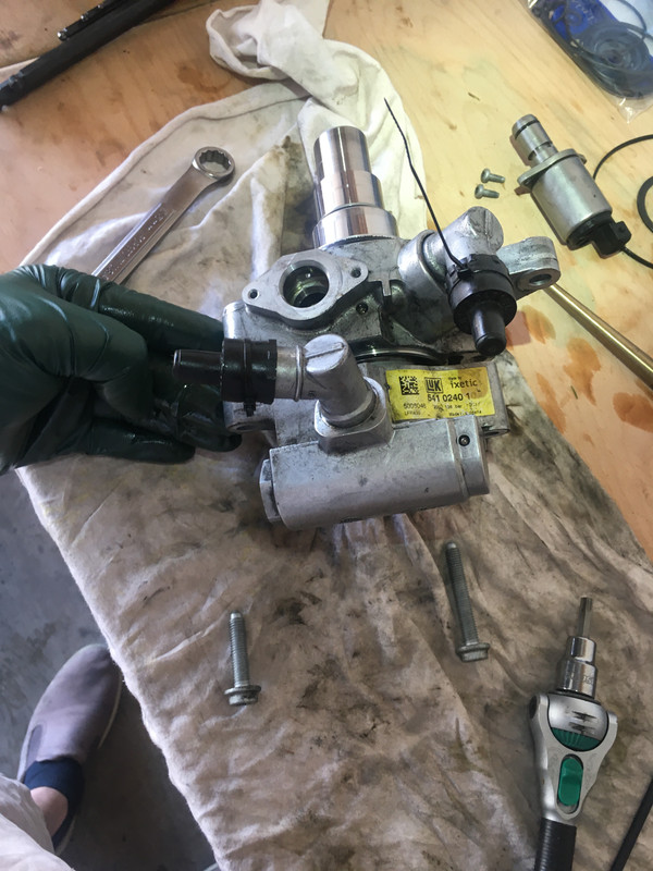
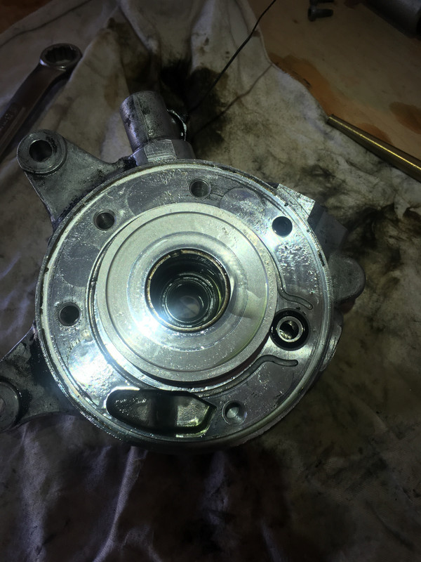
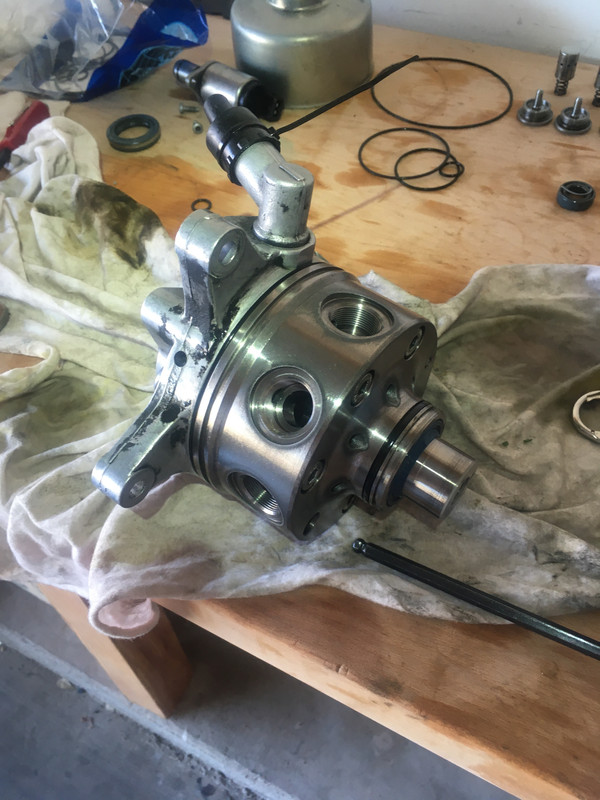
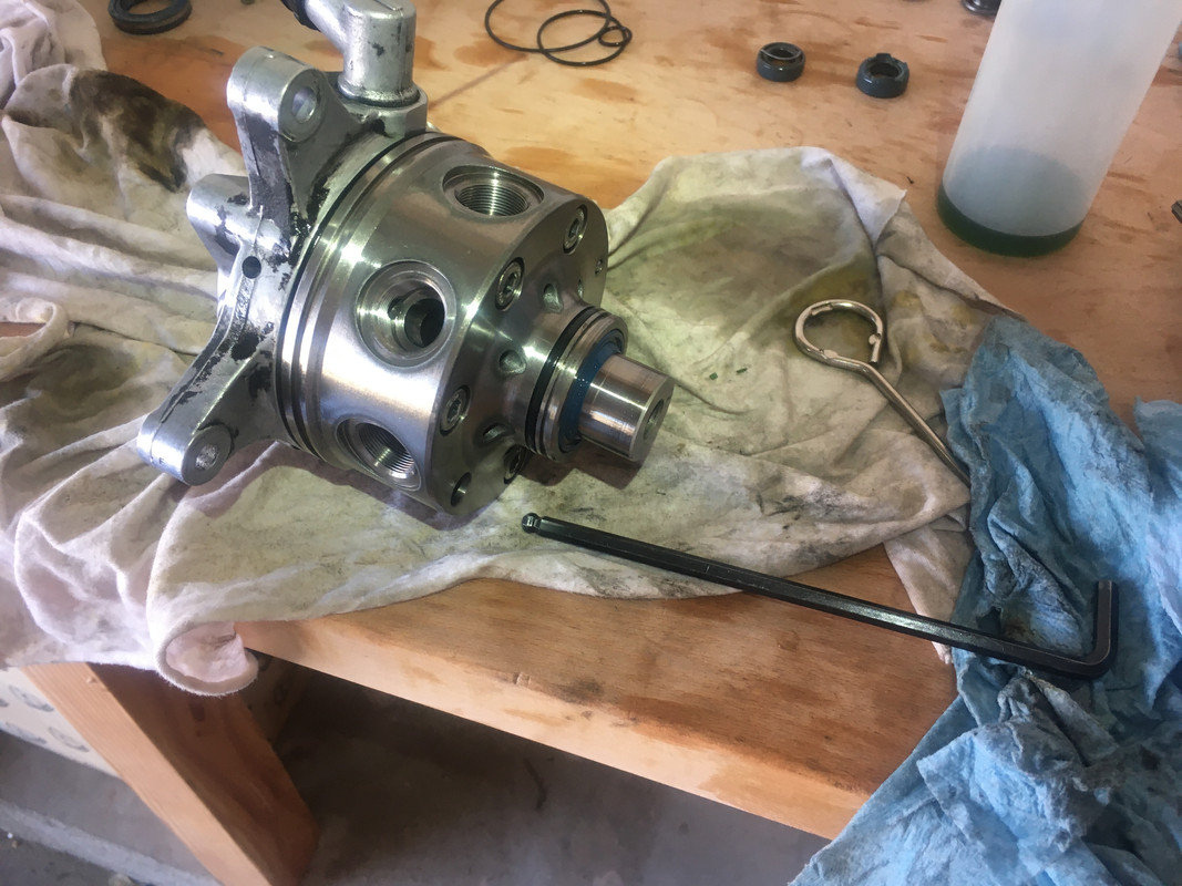
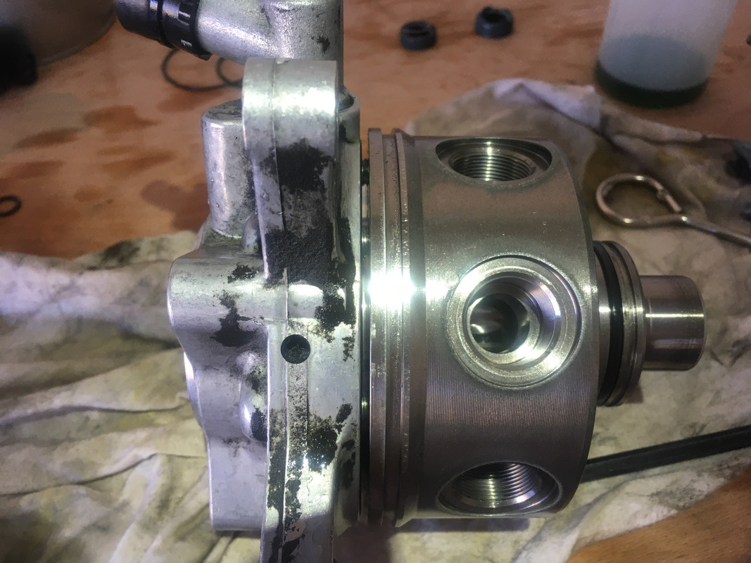
Now you can remove the rear power steering pump. There are two torx bolts of different sizes (T40 I believe) and a nut shaft bolt thing. I tried to document their orientation in the following pictures:
https://postimg.cc/D8ms0zhf
https://postimg.cc/0b3Swq5Y
https://postimg.cc/PCwwbFNB
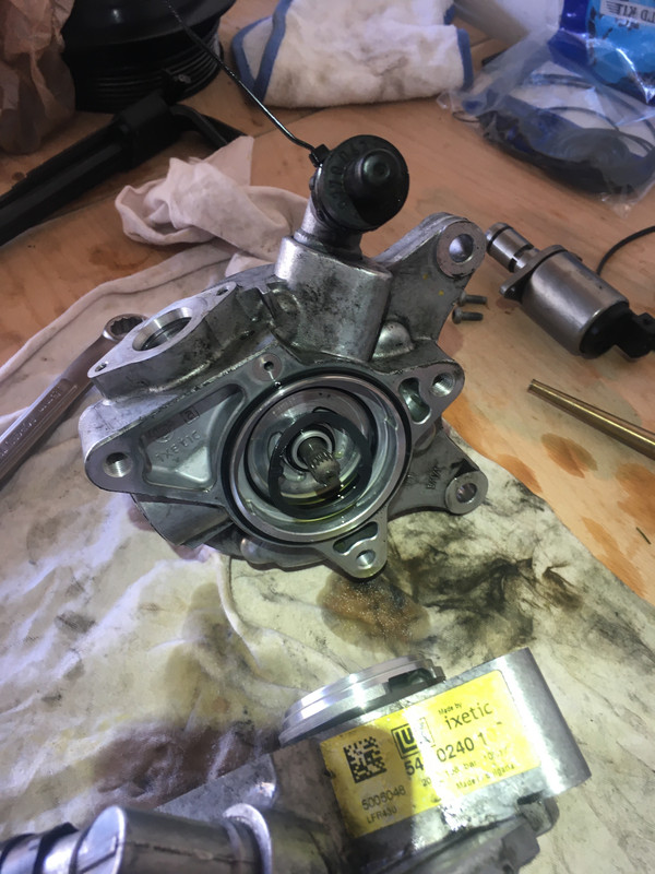
There are three o-rings between the power steering pump and the ABC pump housing. I removed these first lest they fall out on their own and I forget to replace them. These will be replaced last, so put them aside but keep them organized. The Power Steering pump has a Luk part # that I believe can be bought for not a bajillion dollars. If you're having power steering troubles, you might want to investigate buying this part. There is additionally a spring washer thing between the power steering unit and the ABC pump housing. It has two little wing guys that slot into the main PS pump so it doesn't move around. Make a note of its orientation, it'll be obvious once you look at it/see it.
https://postimg.cc/p9MnsYFy
https://postimg.cc/DWQ4HJr6
https://postimg.cc/V0vSJK3Z
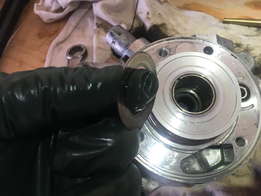
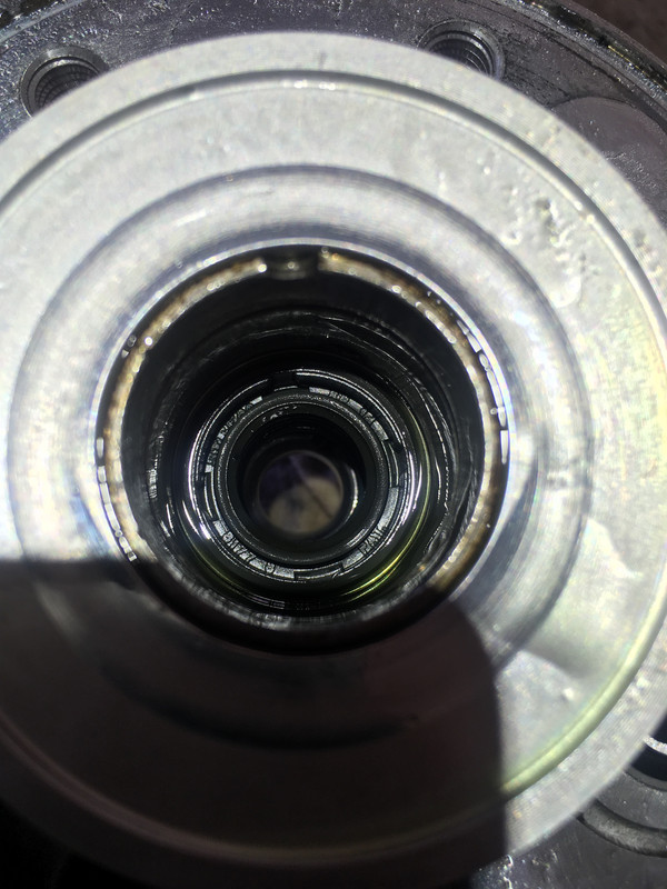
Now you can remove the shaft of the pump. There is a spacer washer between the shaft and the main ABC pump housing.
https://postimg.cc/sQVGrjKr
https://postimg.cc/9RJRX6Nq
https://postimg.cc/F1HkCK7b
https://postimg.cc/F1CdMQLM
https://postimg.cc/SJX2qtLJ
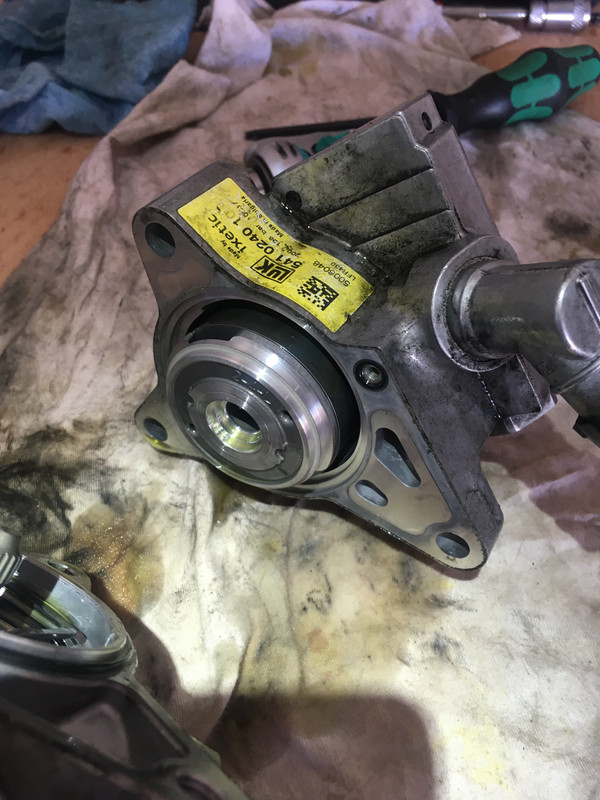
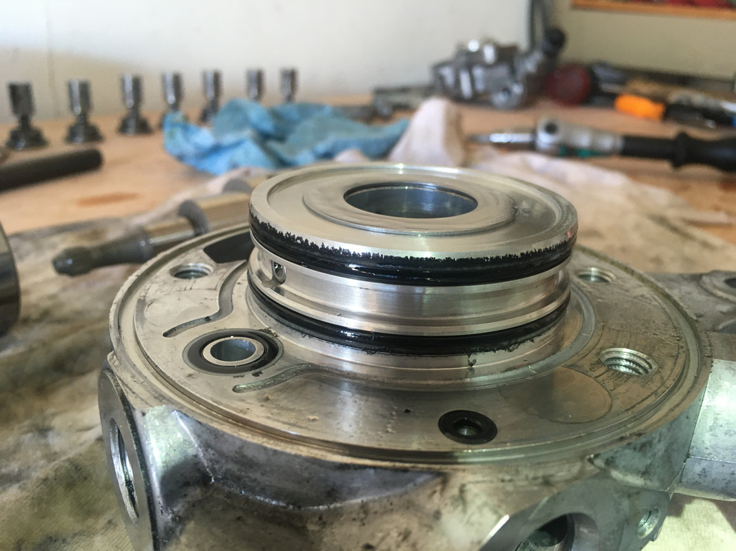
Now we can actually start replacing parts on the unit. I recommend disassembling everything first, then replacing o-rings and seals as you put the unit back together. It's easy to lose track. First up are the two seals separating the Suspension pump from the Power Steering pump. For this the paint can opener was the perfect tool. Take care that you DO NOT SCORE THE SEAL HOUSING. Unfortunately I managed to do so. I believe I pried the top seal out from the ABC side, and pushed the bottom seal out from the PS side with the same paint can opener and a hammer. You'll have to figure this one out for yourself. I don't recommend a pick. The seals spoon up against one another with one being a male seal and the other a female seal. They're installed in the mating position. I have no better way to describe this.
https://postimg.cc/jLGWjQvv
https://postimg.cc/BjHjPLV3
https://postimg.cc/KKbRPG6M
https://postimg.cc/GBj9q0RS
https://postimg.cc/gXkj7Mkc
The seals will be installed together, otherwise there's no way to keep them in their mating position. Put the two seals together and install using an appropriate socket for installing seals. If you've never installed seals before, look up how to do this separately. I found a Craftsman 11/16" socket fit perfectly on the perimeter of the larger (ABC-side) seal, and I used my bench vise to push it in cleanly. I do NOT recommend using a hammer and trying to tap it in straight. I used a tiny amount of grease, and put the seals in the freezer prior to installation. Obviously you should be cleaning up as you go.
https://postimg.cc/9R80HGrd
I don't have pictures; install the big seal on the main ABC pump unit for the shaft. Again I used a bench vise and a socket.
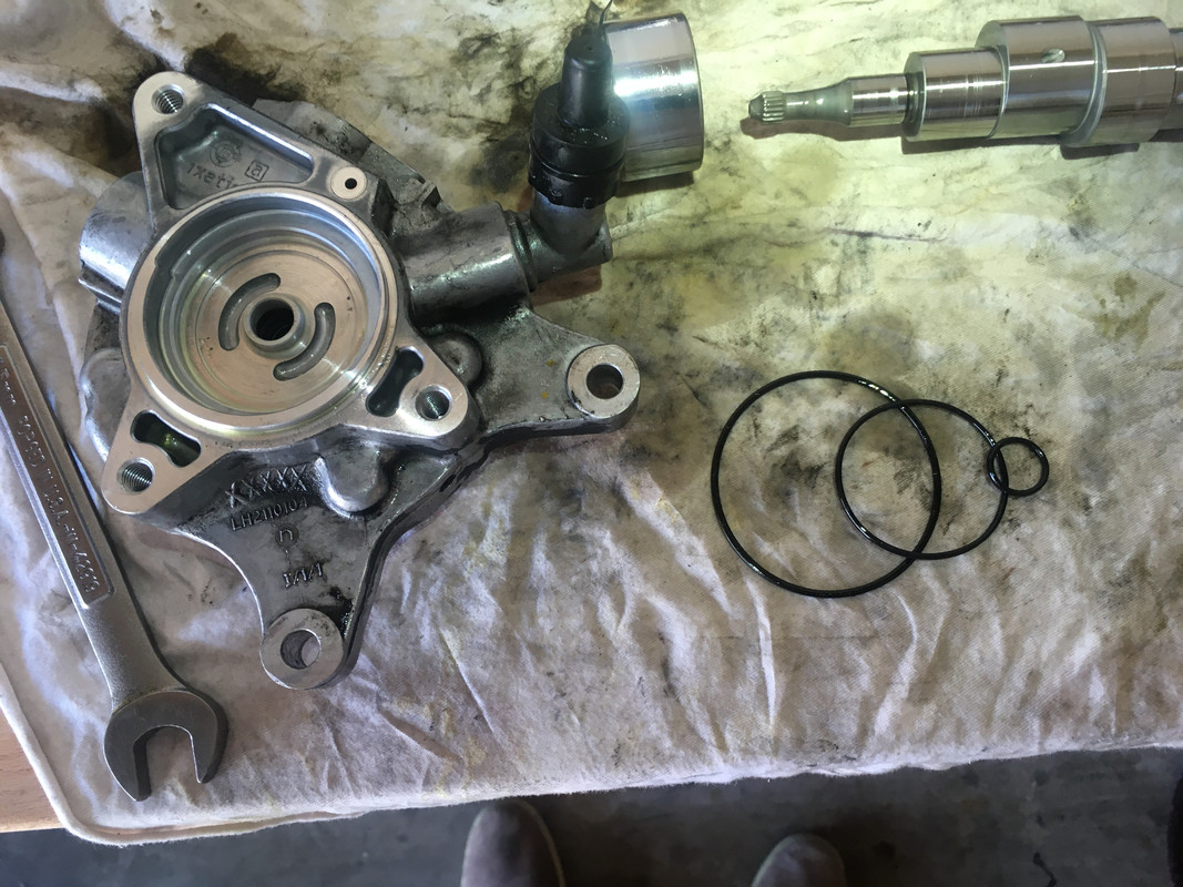
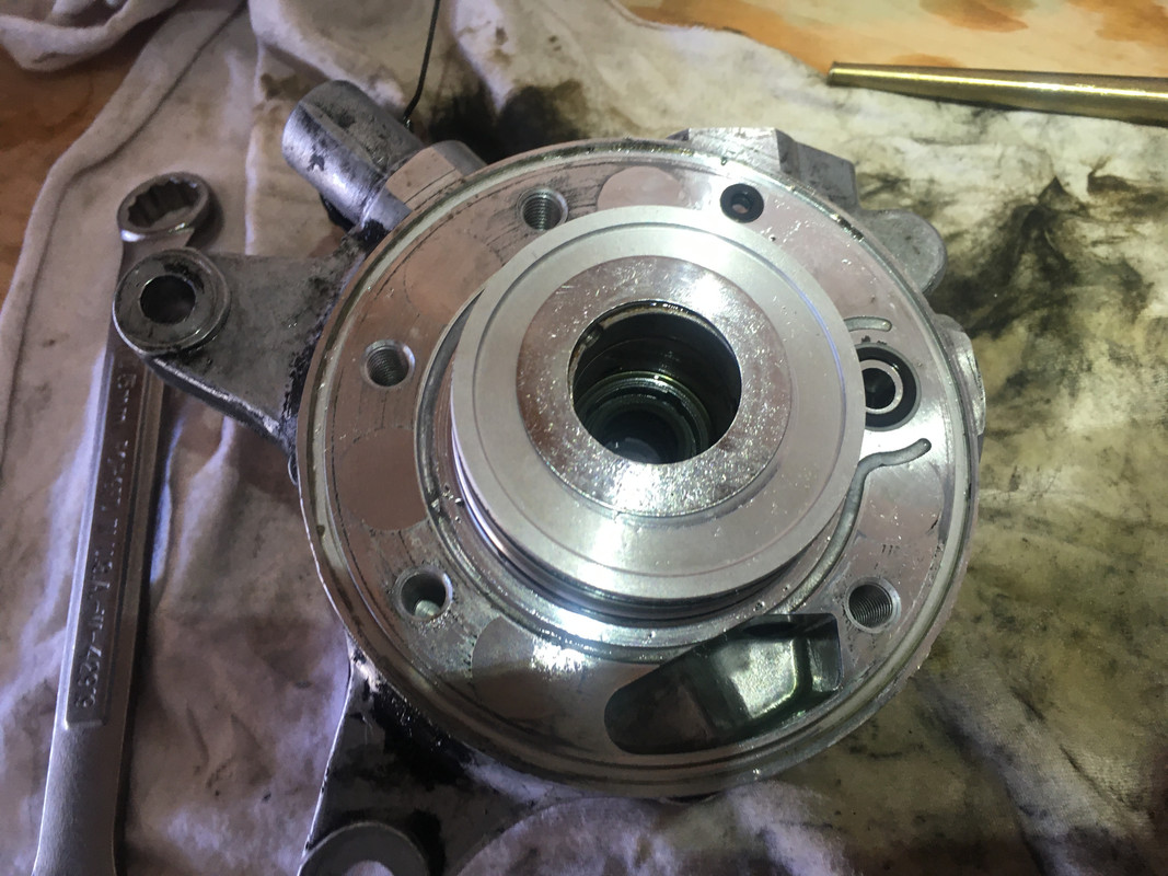
Now things should go pretty fast. Clean everything using shop towels/lint free cloths/compressed air. You can replace the o-rings on the ABC pump. It's very obvious on mine that hydraulic fluid had started slipping past. There are two nylon spacers on the larger o-rings that were not included in the kit. They are oriented OUTWARDS from the center. There are additional nylon spacers around one of the smaller o-rings on the ABC pump housing (not the smallest one). These were also not included in the kit. Use your judgement, replace the o-rings and keep track of which have been replaced and which haven't.
https://postimg.cc/D4SZv8Xt
https://postimg.cc/K4j4rsHJ
Install the shaft, don't forget the washer, and install the main pump. Take care not to **** up your newly installed seals. The kit only comes with one copy, in all likelihood the old ones were ****ed up from the removal process. If you screw this up you probably have to buy a second kit for $100. Use the four hex bolts to slip the main ABC pump onto the ABC pump housing, tightening progressively as you go. You'll feel it very obviously. I have no torque value for these. Tight but not stupid tight.
https://postimg.cc/jC1284VK
https://postimg.cc/vc6BCxMn
https://postimg.cc/zyZBNDXc
Now comes the misery of removing all the sealing compound used for the pump cylinder holder bolts. It's probably not kosher, but I used a wire wheel and a bench press. Kroil didn't dissolve the caked on crap, neither did brake parts cleaner. I also used a pick and a razor blade. This is also where I re-added hydraulic sealant. Loctite 545 is recommended by hydraulic pump rebuilders online (again, this isn't gospel) and comes with specific instructions that I heeded. I'm not sure sealant is necessary, but some thread locker for sure, lest these back their way out. Part of the challenge was cleaning the threads with brake parts cleaner, then adding CHF11S as I re-installed the cylinder w/o contaminating the threads.
https://postimg.cc/753LZv5Y
https://postimg.cc/wt9jtWN5
Now you can install the cover. A hammer is ill-advised here, but it took me some scratching my head to figure out how to do it. I tried hammering first, but it did basically ****all. Eventually I used a garbage disposal flange for a kitchen sink in conjunction with my vise to push it on. This actually worked so well, if all else fails I straight up recommend getting that (hardware store, $10 or so). Then you can re-install the snap-ring. Obviously replace the o-rings prior to reassembling. Don't push on the shaft with the vise. It doesn't take a lot of force.
https://postimg.cc/GBzhvkPW
Continued on next post
Last edited by Fried Chicken; Dec 27, 2024 at 07:10 PM.
Thread Starter
Super Member
Joined: Dec 2007
Posts: 980
Likes: 224
2005 S500 Designo
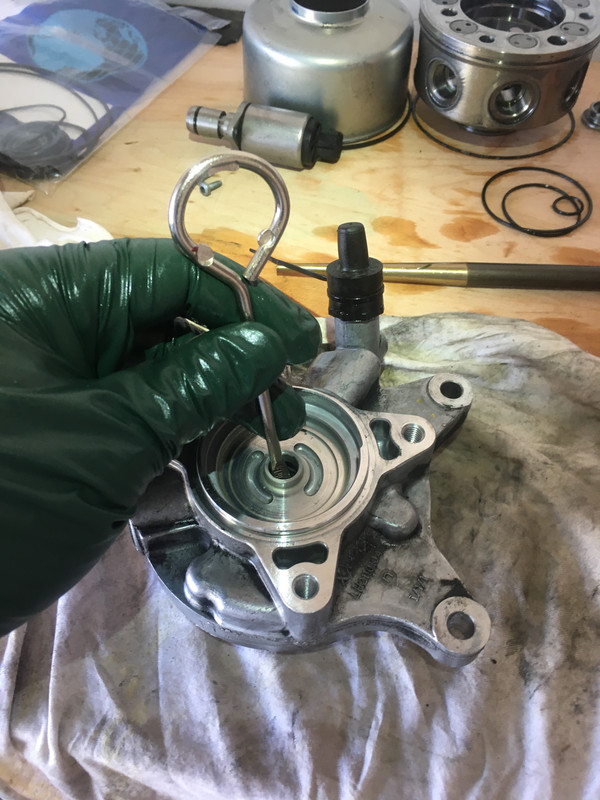
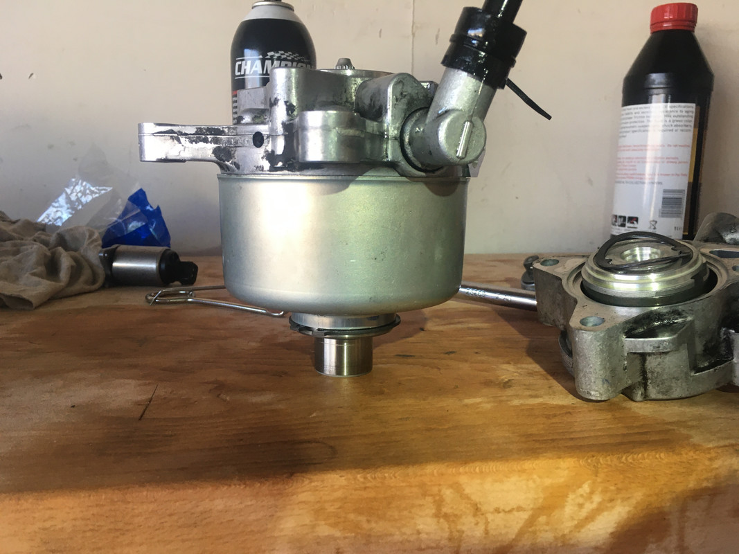
Finally the power steering pump can be re-installed. I have no instruction/advice here other than to take care. You need the three o-rings to sit, the spring washer to sit, and the shaft to sit properly, and then you can use the bolts to push the unit in, snugging them one-by-one. Replace the small o-ring on the hydraulic pump housing prior to reassembly. I recommend not digging into the hydraulic pump. There are small pieces that will fly everywhere. Mine flew everywhere. Here are some pictures you can use as reference. There is a top cover thing for the actual hydraulic pump assembly and two metal rod things, one shorter than the other. The cover will only install flush if oriented correctly with that cover, else there will be a gap. The eccentric circle is for the larger pin. The smaller dowel goes into the pin with the small cutout. Again, I highly recommend NOT dicking with the PS pump unit, there's nothing of value in there.
https://postimg.cc/WF3p8hXh
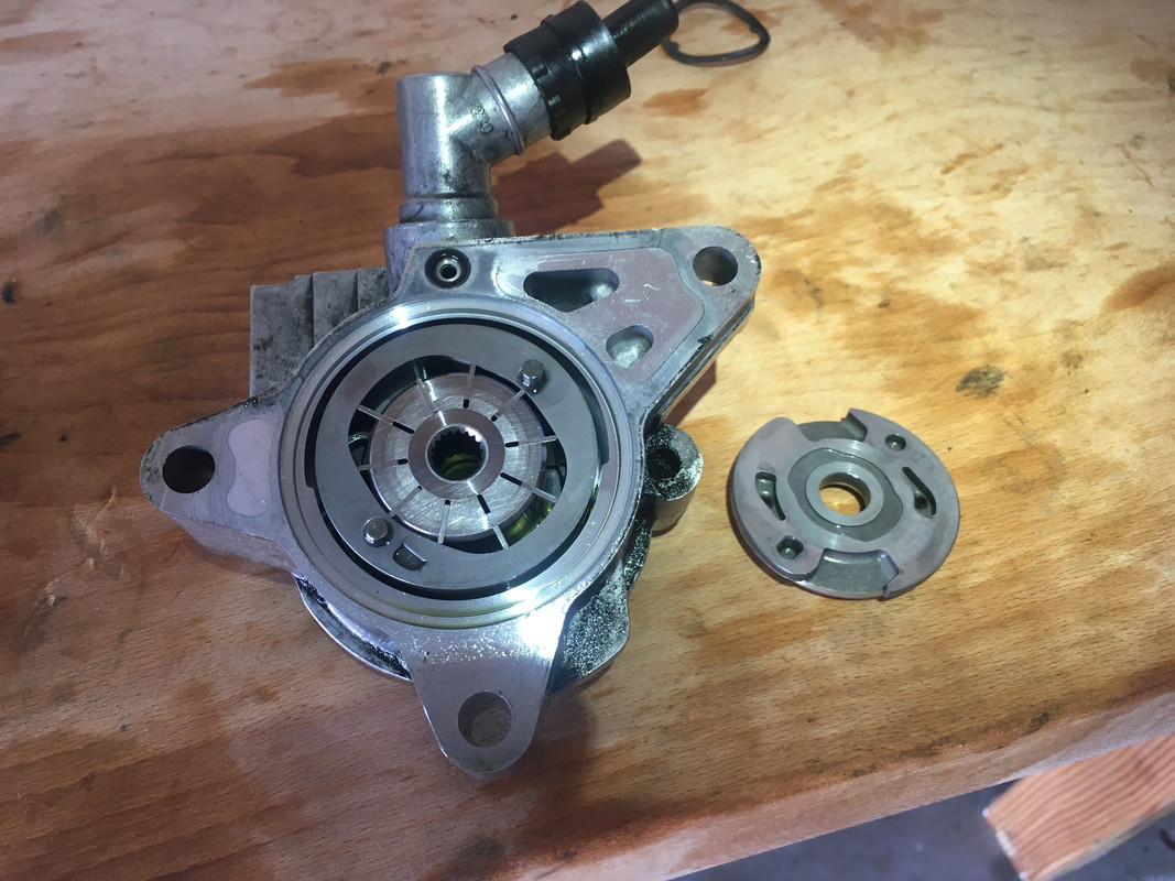
https://postimg.cc/wyGqGgGF
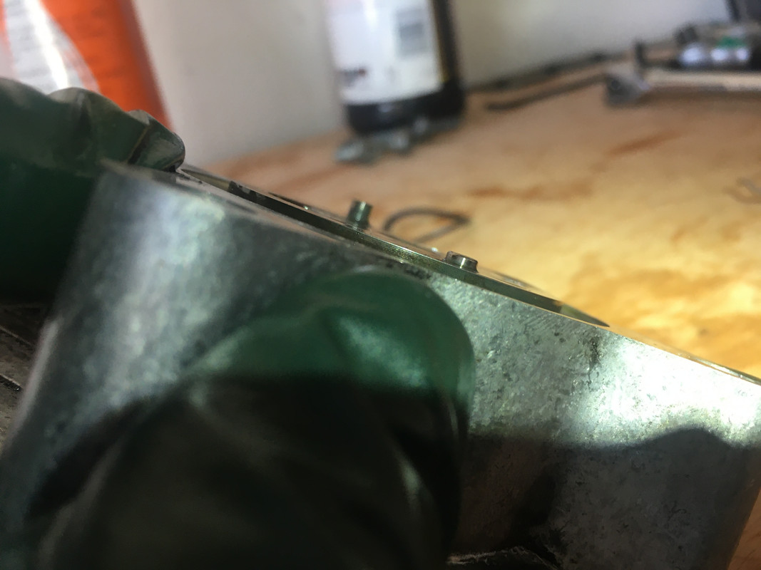
https://postimg.cc/dZZsMgMF
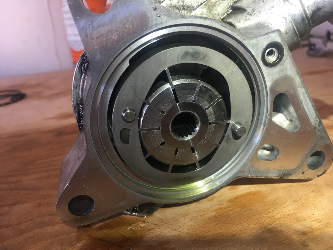
https://postimg.cc/1485NV8d
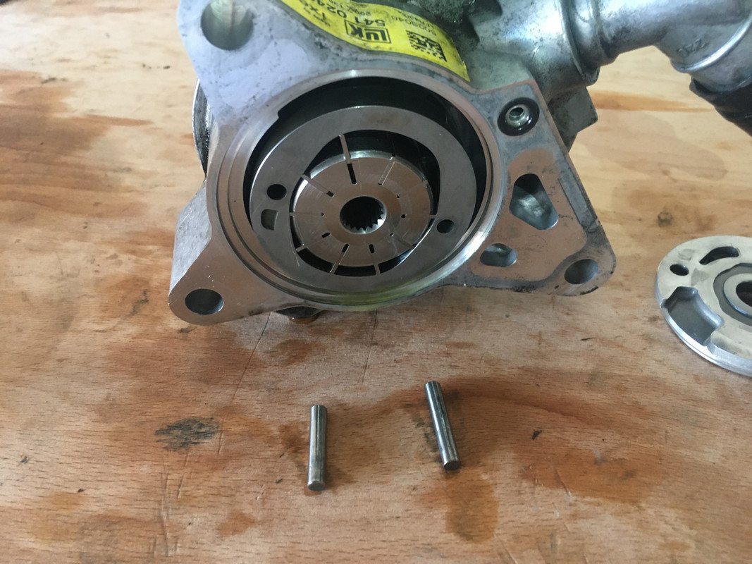
https://postimg.cc/bd4Y0Ybw
Install the power steering pump using the bolts to snug it in one-by-one. I used loctite on these bolts. The main thing is make sure the right bolt goes in the right place, you can reference my pictures from above. Congratulations now you have the whole pump together, but there's still more. The ABC pump has an electric solenoid that regulates hydraulic fluid going into the pump. There are two o-rings on this you can replace (included in the kit). On the power steering side, you can use a big socket (27mm?) to remove some sort of assembly on the inside of the PS pump intake, and there are an additional two o-rings (again, in the kit) you can replace. Weirdly, when I got done I had three o-rings left, one medium-large and two medium-small or something like that.
Final Notes:
It should be obvious, but wet the o-rings with CHF11S as you're re-installing them. Additionally apply CHF11S like assembly lube anywhere you have metal-on-metal contact. Prior to installing the pump, I would prime it strongly, and even after installing it in the car, put everything together, install the pulley, fill the ABC reservoir, and manually spin the pump a little bit to get it nice and primed. If you start the car and the pump isn't building pressure, you have to pressurize the ABC reservoir with 1-2 PSI using compressed air somehow. I have a round piece of rubber with a hole in the middle I made with a hole-bit and a drill (idk what the tool is called, but it makes that exact profile). I can start the car, mash it onto the ABC dipstick port, and squeeze my nozzle in there to pressurize the ABC reservoir. One time it made an audible *click* and then the ABC pump was primed and building pressure.
One final SUPER IMPORTANT note about the pulley. The pulley mount must be heated and slipped onto the pump shaft. I don't know what the best way to heat it is, I think I overheated it once and work-hardened it, b/c I couldn't get it on for the shaft properly for the life of me. Another time it slipped right on no problem. If someone has advice on installing this, I am all ears (Temps, dry ice, freezers, etc). When you install it, it is PARAMOUNT the orientation is correct or the pump will be imbalanced and probably grenade itself over time, in addition to introducing shake in the engine. There is an indent on the front of the pump shaft. That indent must correspond to the cutout in the ABC pump pulley (I'm 99% sure). This will correspond to one of the bolt holes for the pulley mount. Use the pulley on the pulley mount to find out how they align, and then find out which of the holes on the pulley mount corresponds to the cutout and small weight on the pulley. That hole should correspond to the indent on the pulley shaft when installing. I have seen rebuilt pumps for sale by "professionals" who get this detail wrong.
If anyone has anything to add, please share it here. I'm not an expert, I'm just sharing this that others may benefit. After doing all this, I do NOT recommend rebuilding the pump, I recommend buying a new pump or a rebuilt pump from Mercedes. I'm not sure I can recommend any units from any other rebuilders: required information has not been published by Mercedes, and there are too many details that can be overlooked so I simply don't trust them. Again, if someone has good experiences with a pump rebuilder/reseller, please feel free to share.
https://postimg.cc/WF3p8hXh
https://postimg.cc/wyGqGgGF
https://postimg.cc/dZZsMgMF
https://postimg.cc/1485NV8d
https://postimg.cc/bd4Y0Ybw
Install the power steering pump using the bolts to snug it in one-by-one. I used loctite on these bolts. The main thing is make sure the right bolt goes in the right place, you can reference my pictures from above. Congratulations now you have the whole pump together, but there's still more. The ABC pump has an electric solenoid that regulates hydraulic fluid going into the pump. There are two o-rings on this you can replace (included in the kit). On the power steering side, you can use a big socket (27mm?) to remove some sort of assembly on the inside of the PS pump intake, and there are an additional two o-rings (again, in the kit) you can replace. Weirdly, when I got done I had three o-rings left, one medium-large and two medium-small or something like that.
Final Notes:
It should be obvious, but wet the o-rings with CHF11S as you're re-installing them. Additionally apply CHF11S like assembly lube anywhere you have metal-on-metal contact. Prior to installing the pump, I would prime it strongly, and even after installing it in the car, put everything together, install the pulley, fill the ABC reservoir, and manually spin the pump a little bit to get it nice and primed. If you start the car and the pump isn't building pressure, you have to pressurize the ABC reservoir with 1-2 PSI using compressed air somehow. I have a round piece of rubber with a hole in the middle I made with a hole-bit and a drill (idk what the tool is called, but it makes that exact profile). I can start the car, mash it onto the ABC dipstick port, and squeeze my nozzle in there to pressurize the ABC reservoir. One time it made an audible *click* and then the ABC pump was primed and building pressure.
One final SUPER IMPORTANT note about the pulley. The pulley mount must be heated and slipped onto the pump shaft. I don't know what the best way to heat it is, I think I overheated it once and work-hardened it, b/c I couldn't get it on for the shaft properly for the life of me. Another time it slipped right on no problem. If someone has advice on installing this, I am all ears (Temps, dry ice, freezers, etc). When you install it, it is PARAMOUNT the orientation is correct or the pump will be imbalanced and probably grenade itself over time, in addition to introducing shake in the engine. There is an indent on the front of the pump shaft. That indent must correspond to the cutout in the ABC pump pulley (I'm 99% sure). This will correspond to one of the bolt holes for the pulley mount. Use the pulley on the pulley mount to find out how they align, and then find out which of the holes on the pulley mount corresponds to the cutout and small weight on the pulley. That hole should correspond to the indent on the pulley shaft when installing. I have seen rebuilt pumps for sale by "professionals" who get this detail wrong.
If anyone has anything to add, please share it here. I'm not an expert, I'm just sharing this that others may benefit. After doing all this, I do NOT recommend rebuilding the pump, I recommend buying a new pump or a rebuilt pump from Mercedes. I'm not sure I can recommend any units from any other rebuilders: required information has not been published by Mercedes, and there are too many details that can be overlooked so I simply don't trust them. Again, if someone has good experiences with a pump rebuilder/reseller, please feel free to share.
Thread Starter
Super Member
Joined: Dec 2007
Posts: 980
Likes: 224
2005 S500 Designo
I found some resources for getting the pulley mount back onto the shaft:
https://www.practicalmachinist.com/f...7/post-1426944
More DIY machinists discussing things:
http://www.chaski.org/homemachinist/...ic.php?t=88302
I wish I'd documented what worked perfectly for me. One time I got it perfect it slipped right on, the other time I hammered and bashed and it was a nightmare.
Reddit has info on this too: https://old.reddit.com/r/Machinists/..._shrink_shaft/
With a caution from this post
I took some measurements. The pulley shaft is 28mm or 1.102". The pulley mount measures ~1.100" at the back (that first slips onto the shaft), and 1.0975" at the front, it tapers down.

https://postimg.cc/VdD0nGnF
Going by 100�F per .001" per 1" of diameter means at least 500�F of heating to get it on.
Originally Posted by "random internet machinist guy
Larger diameter parts always loosen easier than small ones. A 1" ID sleeve heated to 400F above ambient gives you a touch over .0025 expansion. It'll slide on, but it better be straight and if it hangs up for a split second, your screwed. A 4" sleeve heated to the same temp gives you over .010 to work with. You can throw it on there, and due to larger mass, you may can even line up a keyway or something before it grabs.
More DIY machinists discussing things:
http://www.chaski.org/homemachinist/...ic.php?t=88302
I wish I'd documented what worked perfectly for me. One time I got it perfect it slipped right on, the other time I hammered and bashed and it was a nightmare.
Reddit has info on this too: https://old.reddit.com/r/Machinists/..._shrink_shaft/
With a caution from this post
Thermal growth depends on material. And the dimensions. The mnemonic I have used is .001 per inch per 100� f. This is in steel. This is a generalization and a rough calculation. In steel for every 1 inch of material for every 100� difference it increases or decreases by .001 of an inch.
Do not exceed 550� f for any shrink fitting. Be on that temperature you risk changing heat treats.
Never exceed the draper point. That is the point at which material begins to luminesce.
Most heat shrink fits should be about .001 per inch of material.
So if you have a 1.000 inch shaft diameter. You will heat press 1.001 pin. 100� f difference should get you there.
These are very rough numbers.
I took some measurements. The pulley shaft is 28mm or 1.102". The pulley mount measures ~1.100" at the back (that first slips onto the shaft), and 1.0975" at the front, it tapers down.
https://postimg.cc/VdD0nGnF
Going by 100�F per .001" per 1" of diameter means at least 500�F of heating to get it on.
Last edited by Fried Chicken; Dec 28, 2024 at 10:18 AM.
Thread Starter
Super Member
Joined: Dec 2007
Posts: 980
Likes: 224
2005 S500 Designo
HERE WE GO!
The Last and Final Step. The one I was dreading b/c it ****ed up on me last time and caused a huge nightmare.
You need to get the pulley mount onto the pump shaft in such a way that the pulley when mounted onto the pulley mount mounts to the pump shaft in such a way that the indent on the pump shaft aligns with the cutout on the pulley.
A picture will help here:
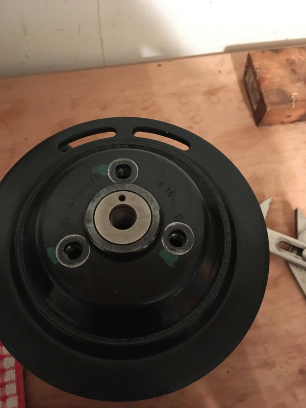
https://postimg.cc/vxhqd7rs
Notice you can draw a straight line from the center of the pump shaft to the cutout portion of the pulley.
To achieve this you must first take the pulley and the pulley mount and line them up against one another. Find the orientation of the bolt holes that allows the pulley to mount to the pulley mount (there is only one way). Once that is done, find which of the three bolt holes on the pulley mount aligns with the cutout on the pulley and mark it using a scribe/blade/whatever. A SHARPIE OR MARKER WILL NOT WORK HERE.
Now you need to heat the pulley mount to some high temperature. The key is that the pulley mount is completely heated all the way through. Machinists will know how to do this properly, I used a cast iron pot on the gas stove with the pulley mount cooking inside. I heated it slowly over the course of about 45 minutes until I got a temperature on the pulley mount of about 450�F. This might be overkill, I am not sure, but better safe than sorry!
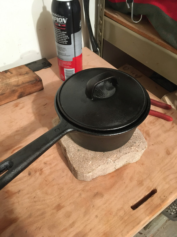
https://postimg.cc/z3Nq8JCt
You may be tempted to put the pump into the freezer or use dry ice. I tried this the time that it failed on me. I don't recommend it because condensation will form and the specific heat of the water will quickly cool the pulley mount as you try to place it onto the pump shaft. I did place it in the freezer this morning and saw no measurable difference in the diameter of the pump shaft so I decided against it.
Anyway, once you have it heated (again: ~450�F worked for me, measured with a non-contact thermometer), you're ready to go.
Use pliers that you can comfortably and confidently grip the pulley mount with, align the scribe mark on the pulley mount that you made earlier with the indent on the pump shaft, and slot it on. Align it vertically so it mounts flush. The pulley mount will cool very quickly, on the order of seconds, and then the pulley mount will be fixed to the pump shaft in such a way that you'll again need a machine shop to take it off. Yes, this is a stressful step. I kept a hammer and some 1/2" impact sockets that fit the pulley mount nearby in case I needed to quickly do some last minute hammering. From the internal design of the ABC pump, this shouldn't cause any damage as the pump shaft sits on the ABC pump housing on a surface that doesn't need precision. Don't overdo it though.
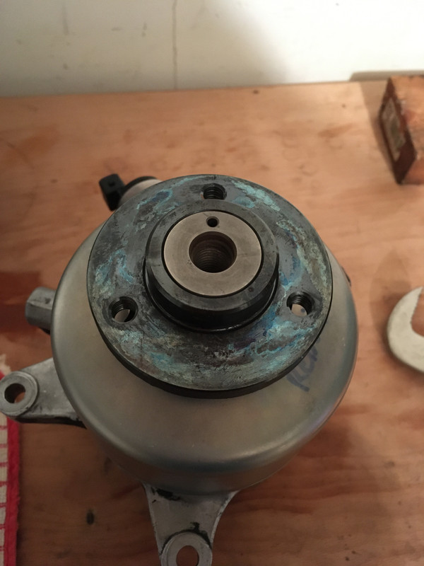
https://postimg.cc/5jmbtZpx
If you look closely at that image, you can see two very small scribe marks I made above the top bolt hole of the pulley mount so I knew how/where to orient it. I used leather gloves during this process. When the pulley mount first shifted on, there was plenty of clearance, almost too much. I had to align it vertically lest it squeeze all the way down and burn the brand new shaft seal I had just installed.
That's pretty much it. If all goes well, the pump should be balanced when installed on the car, prolonging its life and the life of the hydraulic system.
TL;DR:
1. Use pulley to scribe bolt hole on pulley mount that aligns with cutout of pulley, 2. Heat pulley mount to ~450�F, 3. Use pliers to mount pulley mount to pump shaft, aligning indent/hole on pump shaft with bolt hole of pulley mount that orients with the cutout on the pulley.
The Last and Final Step. The one I was dreading b/c it ****ed up on me last time and caused a huge nightmare.
You need to get the pulley mount onto the pump shaft in such a way that the pulley when mounted onto the pulley mount mounts to the pump shaft in such a way that the indent on the pump shaft aligns with the cutout on the pulley.
A picture will help here:
https://postimg.cc/vxhqd7rs
Notice you can draw a straight line from the center of the pump shaft to the cutout portion of the pulley.
To achieve this you must first take the pulley and the pulley mount and line them up against one another. Find the orientation of the bolt holes that allows the pulley to mount to the pulley mount (there is only one way). Once that is done, find which of the three bolt holes on the pulley mount aligns with the cutout on the pulley and mark it using a scribe/blade/whatever. A SHARPIE OR MARKER WILL NOT WORK HERE.
Now you need to heat the pulley mount to some high temperature. The key is that the pulley mount is completely heated all the way through. Machinists will know how to do this properly, I used a cast iron pot on the gas stove with the pulley mount cooking inside. I heated it slowly over the course of about 45 minutes until I got a temperature on the pulley mount of about 450�F. This might be overkill, I am not sure, but better safe than sorry!
https://postimg.cc/z3Nq8JCt
You may be tempted to put the pump into the freezer or use dry ice. I tried this the time that it failed on me. I don't recommend it because condensation will form and the specific heat of the water will quickly cool the pulley mount as you try to place it onto the pump shaft. I did place it in the freezer this morning and saw no measurable difference in the diameter of the pump shaft so I decided against it.
Anyway, once you have it heated (again: ~450�F worked for me, measured with a non-contact thermometer), you're ready to go.
Use pliers that you can comfortably and confidently grip the pulley mount with, align the scribe mark on the pulley mount that you made earlier with the indent on the pump shaft, and slot it on. Align it vertically so it mounts flush. The pulley mount will cool very quickly, on the order of seconds, and then the pulley mount will be fixed to the pump shaft in such a way that you'll again need a machine shop to take it off. Yes, this is a stressful step. I kept a hammer and some 1/2" impact sockets that fit the pulley mount nearby in case I needed to quickly do some last minute hammering. From the internal design of the ABC pump, this shouldn't cause any damage as the pump shaft sits on the ABC pump housing on a surface that doesn't need precision. Don't overdo it though.
https://postimg.cc/5jmbtZpx
If you look closely at that image, you can see two very small scribe marks I made above the top bolt hole of the pulley mount so I knew how/where to orient it. I used leather gloves during this process. When the pulley mount first shifted on, there was plenty of clearance, almost too much. I had to align it vertically lest it squeeze all the way down and burn the brand new shaft seal I had just installed.
That's pretty much it. If all goes well, the pump should be balanced when installed on the car, prolonging its life and the life of the hydraulic system.
TL;DR:
1. Use pulley to scribe bolt hole on pulley mount that aligns with cutout of pulley, 2. Heat pulley mount to ~450�F, 3. Use pliers to mount pulley mount to pump shaft, aligning indent/hole on pump shaft with bolt hole of pulley mount that orients with the cutout on the pulley.

Thread Starter
Super Member
Joined: Dec 2007
Posts: 980
Likes: 224
2005 S500 Designo
I am starting to get pissed off at these cars, and everyone trying to make a buck with their little slice of a specific repair process, only to discontinue support at a later date, doesn't help what are already incredibly stupid cars to own/fix in the first place. As far as I am able, I will try to rectify this with whatever means I can. There was no documentation online of the ABC pump rebuilds. Now people can decide for themselves. I tried to include the pitfalls I found here. One thing I forgot to emphasize in the above post: Take care not to **** up the seals between the ABC pump and the PS pump when installing the pump shaft. Failure to do so will cause ABC fluid to leak from the PS pump into the ABC pump, causing the PS reservoir to go down with use. Go in straight and true when installing the shaft!


