When you click on links to various merchants on this site and make a purchase, this can result in this site earning a commission. Affiliate programs and affiliations include, but are not limited to, the eBay Partner Network.
Good Day,
I initially posed this question in the DIY timing chain replacement thread because I came to the predicament as a result of attempting the replacement, but I suppose it is a really a standalone question.
The short question is: With all crankshafts removed from the engine, is there something that could be causing resistance when spinning crankshaft by hand? Specifically at (within a couple degrees in either direction of TDC).
The backstory if needed is as follows:
1. Attempt to change chain via pull-through method.
2. After connecting new chain and attempting to pull through, slips a couple teeth. We keep going. Chain slips more - we stop. While pulling through we encountered some resistance even though all the injectors have been pulled
3. Take off left valve cover, remove timing sprocket off both sides, finish pulling chain through. Crimp new chain and align all marks - TDC on the crankshaft, timing marking on each side camshaft on each head, roughly correct position of the balance shaft. Call it a night.
4. While rethinking events at night realize that there should have been no pressure when all camshafts and injectors were off and spinning crankshaft to finish pulling chain. Consider having bent a valve when we continued pulling after teeth slipped.
5. Take camshafts back off, spin engine to where resistance builds up at TDC, try pressing each of the valves. All valves except cylinder 1 and 5 move freely unrestricted. Valves on 1 and 5 all extend same short amount down until presumably douching the piston. To me, fair indication that pressure is not due to piston hitting valves.
6. Start researching what else could be causing this resistance. 2 running theories is are that I damaged crankshaft sprocket while pulling the chain through, or dropped carbon into cylinder while cleaning intake valves. Awaiting on camera to arrive to inspect cylinder and sprocket in close detail.
I am quite obviously not a mechanic (and perhaps bit off more than I should have) and am wondering if this is perhaps normal and caused by something I do not realize and I am just wasting time trying to chase it.
Didn't get a camera to fit in injector holes yet, used the one I have to inspect the sprocket. All teeth look fine. Decided to double check valves... I was very wrong guys. A couple of exhaust valves on cylinder 1 move different from each other. Looks like head-off-o-clock for me.
Quite demoralized, will be starting on the weekend after I clear my head. I have not seen any vids or posts on head removal, so perhaps I will try to make some documentation. I have WIS at my disposal, and will turn to this forum for help when I am stuck I suppose.
I am at a point where I have removed both heads and found the cause of the resistance - soot that fell into #5 cylinder compacted and was not allowing it to come all the way up.
After last post, I pulled the right head which is where it felt like valves were moving erratically when I tested them. To my surprise all the valves were fine on all cylinders in the head.
I took a break and over some food realized the fault in my logic testing the valves the second time around. First time i pressed down on the stems with pliers and all valves moved the same. It was difficult and pliers wanted to slip. Second time around I thought I found a better solution. I used a 1/4 socket extension with the hat of the extension to go over the stem. That way the extension would not slip, and I put a big socket on the other end so that it would be comfortable to press down with. This is when the valves moved wildly. I realize now that the socket connector is deeper than the valve stem protruded and I was pushing on spring instead of the stem first and perhaps catching the keepers on others.
The resistance remained and my hope was that i failed to close the valve when I was cleaning the intake ports and the soot fell into the cylinder. Upon taking the left head I found about 1.5mm of soot/carbon compacted on the piston. After head removal, there is no longer resistance.
Learn from my mistakes if you are setting out on this for the first time! ENSURE VALVES ARE CLOSED BEFORE CLEANING INTAKES! #5 cylinder, you can see the soot sticking at the top too my super scientific measurement of how thick the soot was
Given the piston movement sequence in OM642, how many degrees does it take to move the crankshaft from #1 piston at TDC to #4 cylinder @TDC?
Good Morning,
Lucky for you, I invested in the angle gauge in anticipation of setting a number of the bolts in the reassembly
If no one gets back to you before I get home tonight, I will spin my crankshaft and tell you what I find!
Given the piston movement sequence in OM642, how many degrees does it take to move the crankshaft from #1 piston at TDC to #4 cylinder @TDC?
Hello again.
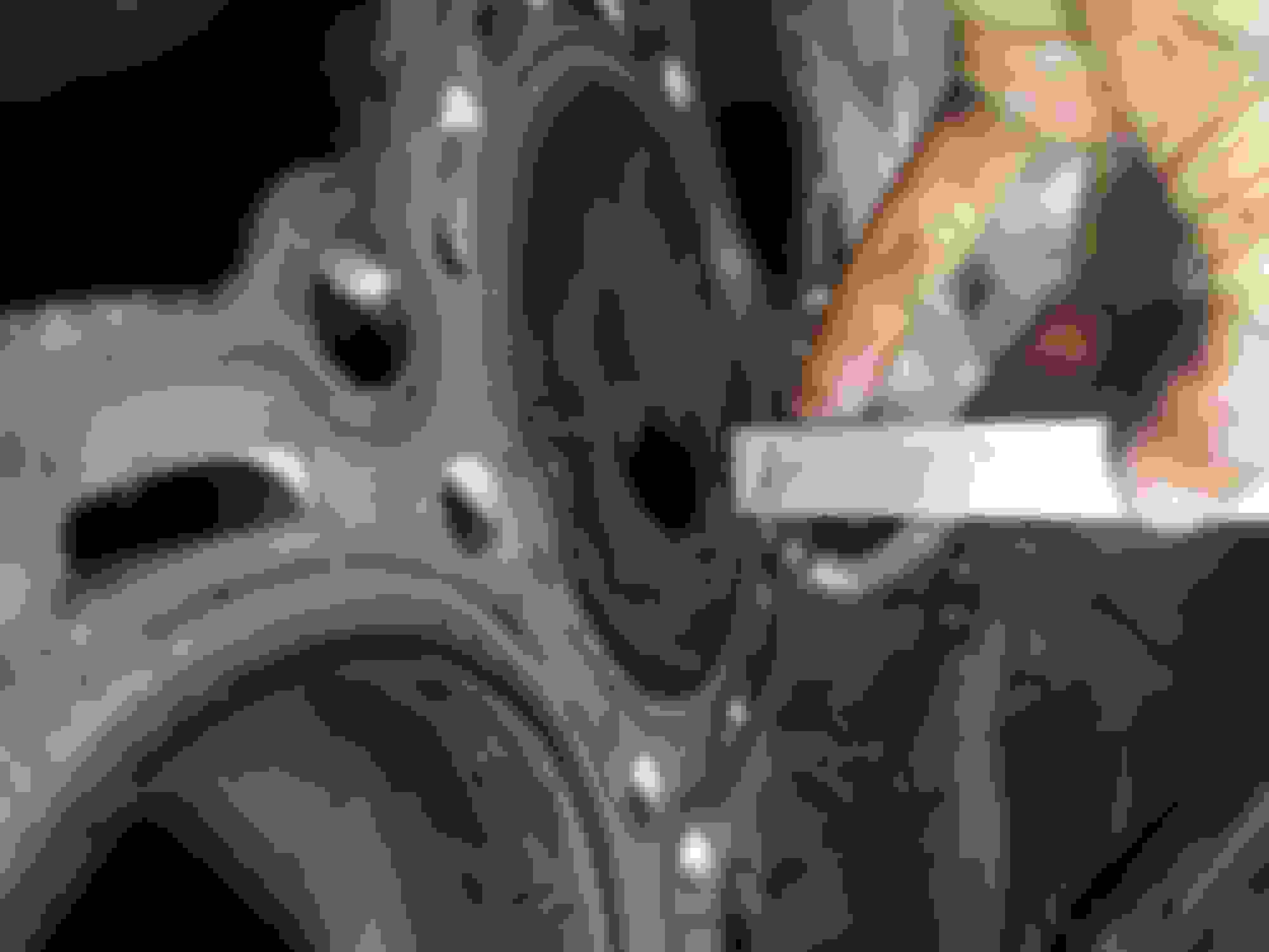
I tried spinning the crankshaft. I found that #4 piston reaches tdc at 115 degrees from #1 dtc, and stays there for 5 degrees until 120. I am not a mechanic and do not want to lead you astray here, so I will tell you what I did and you can interpret it yourself in case my interpretation is wrong:
1. Set crankshaft wheel to TDC, visually #1 cylinder at the top.
2. Reset angle gauge to 0
3. Turn the crankshaft until the piston in #4 visually stops moving up, gauge reading at this point is 115 degrees
4. Continue turning crankshaft until the piston in #4 starts moving down, gauge reading at this point is 120 degrees
Yes it does! Thank you! Any time you take intake manifolds off, you want to clean those head ports but as you found the hard way, if those valves are not closed, a lot may end up on the piston.
Final question: how many degrees does it take to move piston #1 from TDC exhaust stroke to compression stroke? i.e. how many degrees do you have to turn the crank from cylinder #1 being at TDC to the point where cylinder #1 begins to move up?
Final question: how many degrees does it take to move piston #1 from TDC exhaust stroke to compression stroke? i.e. how many degrees do you have to turn the crank from cylinder #1 being at TDC to the point where cylinder #1 begins to move up?
Curious why you need that. Just to clear up though, I can only tell when the piston will be at BDC, I cannot vouch for it being beginning of compression or exhaust stroke. That will depend on the position of the camshaft. The crankshaft wheel does 720 degrees for camshaft to do 360. Hopefully someone can correct me if I am wrong.
I will get you the BDC once I get back to the car. What you said in the previous post actually made me want to measure angle for each piston at TDC so that anyone in the future can know when each cylinder's valves are closed without taking valve cover off. So I was going to do more measurements anyway
I wanted to know when the intake valves are closed for each of the pistons. This happens when the piston is on exhaust or compression stroke. Perhaps you can simply look at your block now, set #1@TDC, and tell us which ports to clean. Then how much should we turn the crank so that we can do the rest?
My plan was to put crank a little before #1TDC and figure out (by calculating from your data) which cylinder intake valves are closed at this crank position, then move crank sufficient amount of degrees to close the rest of them.
So as to minimize the amount of cranking you will have to do... Gotcha. Ok well I made measurements, sorry it took a while. I gotta say this is not a very accurate way to measure this angle, but it should be close enough to know valves are closed imho:
Mercedes SLR McLaren 722 S Is Extremely Rare Example Modified by McLaren
Slideshow: A one-of-one U.S.-spec Mercedes-Benz SLR McLaren Roadster became even rarer after a factory-backed transformation at McLaren's headquarters.