When you click on links to various merchants on this site and make a purchase, this can result in this site earning a commission. Affiliate programs and affiliations include, but are not limited to, the eBay Partner Network.
Car data :
2014 E400 W212.0 facelift with 677 Suspension. Car model is W212.065 as per EPC/WIS. Rear wheel drive, not 4Matic.
Below is my conclusion.
Now, for the experts on wheel alignment , what would you reccomend me do ?
01. Install Camber correction bolt for LEFT wheel
or
02. Remove Camber correction bolts for RIGHT wheel.
I will re-measure and adjust the sway bar links for correct length to 1mm accuracy if I can, which is tough to do because it is angled
These links can only be installed when wheels are floating in the air, so on a normal ride height, it does have a decent pre-tension pressure.
Since these links are a bit behind the front strut as installed, I think its does effect camber to some point if I set it too long by mistake.
I added my original excel file of all alignments performed since day 1, if anyone wants to see the historical numbers.
I would add the Camber Bolt to Left front. Caster can effect the pull of a car(depending on the roads crown angle) slightly but will not effect tire wear. Incorrect/split camber can cause odd tire wear.
Add the bolt and see how everything lines out. As you can see from your data, changing one does effect the other.
I need to share the tools ( and custom tool ) needed, just in case others want to proceed and will DO a PROPER TORQUE-ing on these correction bolts.
Finally managed to get the correct NUT for the correction bolt on late Friday.
Out of 4 correction bolts set, 1 has a standard NUT and not the taller raised CORRECTION nut.
Supplier seems to cannibalize that nut and passed me an open packaging with all proper parts, except the NUT is standard one.
For CASTER , only a low profile crowfoot wrench can be used for torque-ing purpose, socket type will hit the subframe. NOTE : SWAY BAR NEED TO BE REMOVED !!
Without the raised type correction bolt, using a torque wrench with a crowfoot wrench on the nut for CAMBER to set to 100Nm is a nightmare due to the subframe "LIP" design hitting the 1/2" drive.
Nightmare for me who only can raise the car to Quick-Jack maximum height. If one has a standing man height car-lift, he will have more room and strength to do stage 2, a 180 degrees clockwise turn of the bolt after 100 Nm.
For CAMBER and when using socket, only an impact type short socket with custom drilled middle hole to accomodate bolt protrusion, while being short enough not to hit the steering push rod. NOTE : a typical low profile socket WILL NOT WORK even if you custom drill a larger hole, it is too short and the end of the bolt thread will hit the socket.
If one does not care about torque-ing the bolts/nuts, then a ring wrench size 21 with 40 degree angle will do.
But since my life at 200+ KM/H depended on all the 4 bolts/nuts being properly tightened/torqued, me is not taking any short cut.
So late Saturday nite, I done the LEFT CAMBER bolts installation.
Have not got to do alignment yet, fastest is tomorrow Monday.
I just done a test drive today Sunday and it is so WEIRD !!! I know my car is "crabbing".
The way I feel the car straight line tracking and other personal sensors on me .... something is way OFF, more than just a TOE value being OFF.
The thrust angle I am sure is heavily effected and 1 more issue which I will only know tomorrow after seeing alignment values.
When I done only 3 other bolts prior to alignment 18th Aug 2020, I did not sense the "crabbing" phenomena.
Yes my steering became like 10 degrees off axis to the right when going straight... that was it only.
The TOE value crazy change as below :
Today, the steering is also approx 10 degrees-ish off axis to the right when going straight, but with that "crabbing" sensation.
18 Aug 2020 photo is BEFORE alignment done.
ADD : The SuperPro sway bar link ball joint for right wheel is too short by 2mm-ish. I have re-set it, hopefully I am now accurate to <1mm.
Shall update. I am just so curious and since it is a Sunday today, me share early some findings.
.
Last edited by S-Prihadi; 08-23-2020 at 07:20 AM.
Reason: add info
Wow, my bolt install looks like a walk in the park lol.
You've put a lot of effort into describing cause and effect, this will be a great resource for others.
At first I wondered impact of that shorter balljoint on alignment values - if the sway bar was twisting at straight position and creating "pull" on one side. Not sure unless bar was disconnected to see.
I think also thrust angles are behind the crabbing feel and that next alignment should get the car squared up. Those bolts would give you enough latitude now for as much adjustment as possible on undamaged suspension.
I also agree on proper torque on stuff like this, also that holding the bolt in position is critical when tightening the nut. Otherwise the tabbed adjustment washer/mount arrangement is ruined allowing the arm to shift.
is our car so much difference on working space with the nuts I speak of ? Lucky you if so.
During the 5th alignment on 18th Aug 2020, where LEFT wheel did not yet get CAMBER correction bolt.
I measured for fun the "romes angle"...LOL
When I re-done the sway bar links length, I actually tried to measure angles on Bilstein B4 strut and also on camber arm. Camber arm has that two dots for Romes tool.
I also tried measuring sway bar deflection while at it to see what kind of preload angle the sway bar liks are at when at ride height.
HOWEVER.....It was dangerous if using a Quick Jack to do above, as I need to jack up my suspension system, at its lower ball joint to where suspension height equal to actual height when car is on the ground.
This means I need to thrust up 490 kg kg per wheel, to get my suspension height as normal ride heigh and that made the 2 front supports of the Quick Jack hanging loose not supporting the car....as the car is physically tilted up at the front.
So car rear side sinks down. LOL. Can be dangerous, but I have taken extra pre-caution with my own copy-cat-from-someone of a jack-able wheel support at both rear wheels and place one of the same with wooden block, at the front subframe middle support pad.
The 3 extra supports below is not supporting the car...yet...it is there just in case if the Quick Jack blow its hose/s or valve/s or seal/s and it will catch the car and I can survive being under the car at height clearance enough as not to become a salami
However, it is not as easy as I imagined pushing up to 490 kg ( 1,090 lbs ) each, on both front wheels at the lower ball joint.
I need to have at least 2 more of the green hydraulic jacks ( so total 4 ) for 2 rear tires to also have its supension pushed up , otherwise I will flip the car if both front wheels get 490 kg KG upward thrust each.
490kg will equal to 36.5cm (+-5mm for my measurement error ) from fender lip to wheel bearing center distance, aka normal ride height.
Since there is Caster angle, measuring the above distance is a bit tricky as suspension is raised up using the jack.
At totally suspended in-the-air front suspension, the distance of fender lip to wheel bearing center is 46cm.
The sway bar link at this suspended in-the-air , the lower one for the sway bar itself, this ball joint center is lower by 2ish mm compared to its hole at the sway bar end if ball joint's shaft not inserted,
but top side ball joint already properly installed on the Bilstein B4.
Since sway bar angle/flexing on one side effects the opposite side too, it is so time consuming to do all the 3 angle measurements.
01. Angles on Bilstein B4 strut, as though as CASTER
02. Camber arm level, like a Romes.
03. Sway bar deflection
I need to have 2 precision hydraulic jacks ( expensive ) and buy 1 more of that digital clinometer the long one ( easy & cheap)
My cheapo green jack is not very precise , more so in release/down mode.
Anyway I gave it a try to 43cm fender LIP to wheel bearing center or approx 3cm of upward thrust to both front suspensions.
Measurement 1 - suspension totally floating in the air
If only I have 2 long inclinometers ( I got 2, but one is a short version), I can remove the in-accuracy caused by me switching use between left and right.
Best I buy 4 of these long and 2 of short inclinometers if I really want to measure. Maybe next time when I got more freetime.
A special pre-caution for those trying to do the same as I did. I mean pushing up the suspension system with a "cross angle* " trolley jack , to ride height. This caution does no apply to bottle type jack with 100% straight up thrust without angle, but you may not achieve the required height or enough suspension movement.
First, orient your trolley jack like below, and choked it like I did. Make sure rear wheel of jack ( caster wheel ) is lined up straight 12 o'clock.
If a trolley type jack as above is oriented towards car rear or front ( 90 degrees different to above image), it maybe catapul-ted some distance when you create some
suspension movement on the other wheel. Yep, it happened to me ... LOL
Measurement 2 - At 43cm fender LIP to wheel bearing center.
After this I stop trying to measure when pushing for <40cm fender LIP to wheel bearing center, because I saw the car's front side jacking pad has lifted itself by like 5cm above the Quick-Jack.... dang !!!
I also find that moving around the inclinometers to different measuring spots, caused in-accuracy by placement for sure.
The point is, I can see the sway bar deflecting 14.00 degrees to 10.70 degrees for righ wheel and 13.90 to 10.50 degrees for left , from a mere suspension travel change of approx 3cm, while
there will be another 6 cm more to go or total suspension travel of approx 9cm at the least.
Right wheel assy totally floating in the air, BUT before camber and caster correction bolts installed. The inclinometer is sticked to the Romes dots, unlike previous photos where I stick it
not at the Romes dots but the flat part of the arm. These two different reading points has some 0.X degree difference reading as I recalled.
Let see what tomorrow alignment result will bring.
I am only worried of 1 thing, hence I asked in this forum : https://mbworld.org/forums/e-class-w...ce-please.html
I am worried that because my car is locally assembled, what if the techy who installed all the caster and camber bolts, accidentally swap location of bolt head to nut.
For a non correction camber/caster bolts, this mistake is 100% fine, switching place of bolt head and nut will not change anything.
However, when we use correction bolts, its will be the opposite effect to what the WIS showed.
Take a careful read to below WIS : ( also applies to Caster )
MB Germany did not state specifically that this method of bolt groove orientation can be for both left and right wheel.
It only showed that bolt groove is to be opposite of washer's unique identation* ( *whatever the technical name is ?? )
The above caused some headache for me, till I seen how the bushing center funny shaped tri-hole, its notch to push or accept correction bolt groove for left and right arms is not the same orientation.
MB installed the very same bushing in opposite orientation between caster/camber arm for left and right wheel .... LOL.
This way MB can show in WIS how to orient correction bolts groove for intended ADD/REDUCE angle, same method for both left and right wheel.
BUT....MB Germany did not show explicitly where is the nut or bolt head position in respect to front of the car.
This is the reason I asked forum assitance for photos of bolt head vs nut position in respect to car front...... for un-touched ( no correction bolts ) W212.
I am prepared for worst case scenario.
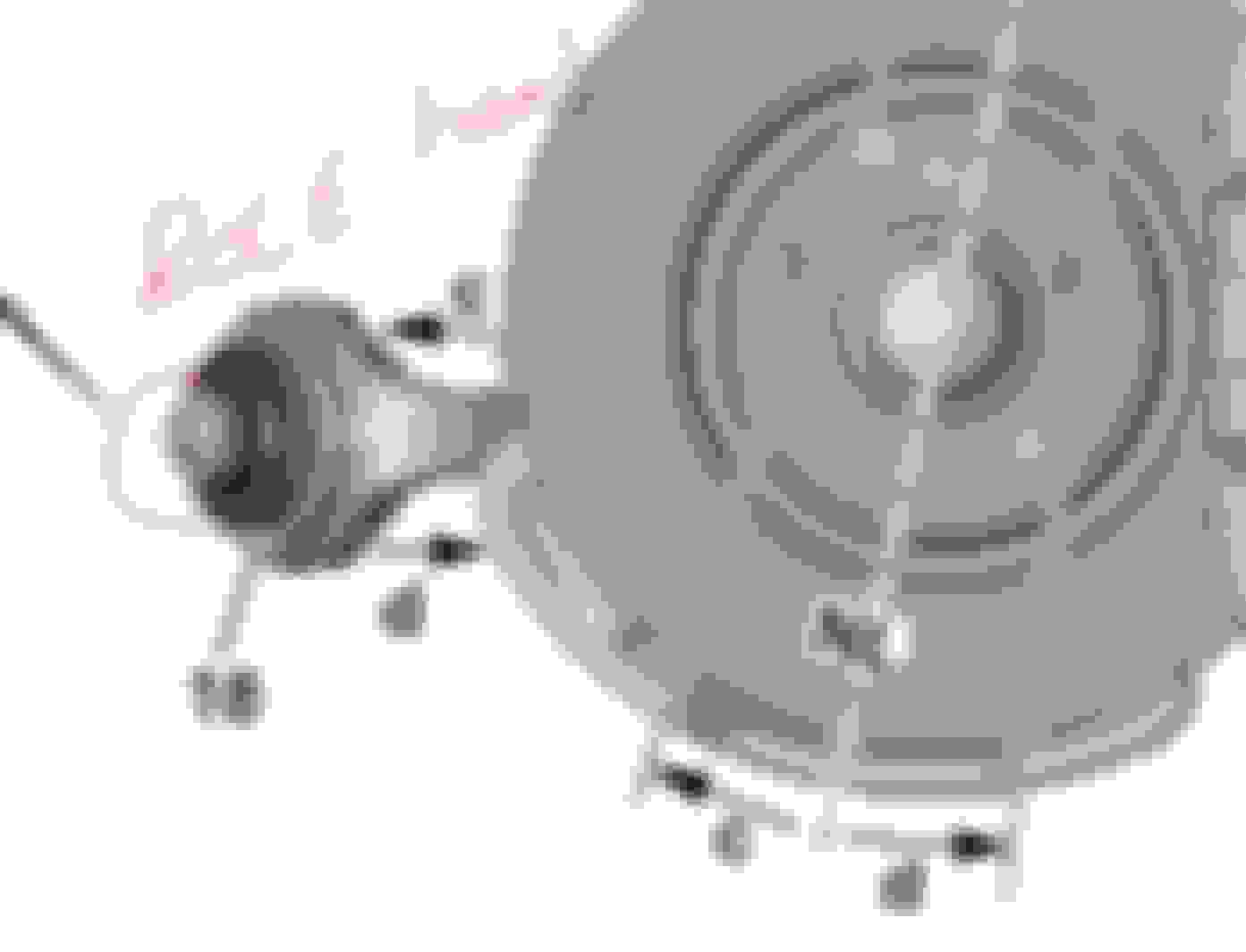
Now, see below and tell me, which bolt head position is correct ? Ain't it confusing..... LOL
Close up of bolt head
I maybe over-thinking about this correction bolts thingy, but my right Caster increased by only 1' instead of supposedly 20' is a big mystery which haunt me these past few days.
And then my LEFT caster increased by 40' which is supposedly NOT to happen.... made me think LEFT is correct and RIGHT is wrong with opposite effect = 40' of change.
Wrong as in the bolt head position in respect to car's front.
The 6th alignment values do not make sense............ LOL. The CAMBER part. CORRECTION FOR **AFTER** Thrust Angle. It is -0* 01' not a positive value.
Correction bolts head groove + special washer orientation is correct, CAMBER
However, the way I see it is : as below 2 photos......... Any comments ?
Last edited by S-Prihadi; 08-24-2020 at 07:22 AM.
Reason: edit typo
yep, your last 2 photos and descriptions are correct! depending on how you install bolt will add or remove from non-adjustable bolt readings, in theory, of course!
If right wheel caster arm pushes into the Bilstein B4, and not pulling the B4, it will create negative caster ( reduce positive caster ).
Trying to track data for verfication and can a -2mm too short right side sway bar link bring such effect , aka confuse me even more
What I will do : 2 choices
01. Swap correction bolts orientation of the groove ( and that unique washer ) from A mode to B mode and/or C do D mode ....where applicable, while retaining bolt head position the same...in respect to the car front side.
02. Swap position of bolts head in respect to car front side, while retaining A, B,C or D mode as per WIS.
I think also changing the bolt position "should" shift alignment into spec. I'm not sure about swapping bolts side to side entirely - unless I'm not looking at it right, the bolt can shift to alternate washer position without needing to move to the other side?
Also, if you change the bolt position and still cannot get within spec, I believe it may be due to something being tweaked that is not visible to the naked eye or tool level of the diy home mechanic. In my case one of the front struts is very slightly bent, no marks, nothing visible, but apparent to the alignment tech upon review and interpretation of the machine readout. So the 4 alignment bolt installation was needed on my car plus the experience of a good alignment tech that could look at the whole picture and make adjustments/road test appropriately. Other factors besides strut could be wheel or one of the control/thrust arms being ever so slightly tweaked, none of which may be seen on visual inspection. I'm assuming bushings are ok and not allowing excessive movement under weight or load.
I think also the rear suspension factors into the crabbing as its a 4 wheel thrust alignment? So there's additional factors to be verified. You're right about suspension engineering!
Very high level of analytics, interesting and appreciated as you develop a final solution.
Damn, I screwed up on bushing pre-tension protocol for last job, the LEFT camber bolt.
This could effect how the car response and contribute to the "don't feel right" sensation I am feeling after 6th (last ) alignment completion, because that camber arm then has approx 12-13 degrees of pre-tension or pre-twisting force on the
rubber bushing while at normal ride height.
Certainly that bad value LEFT side camber also contributed to "don't feel right" sensation.
Please don't mind the missing "V" and some other alphabet on the above print. I do not know why when printing WIS to Microsoft XPS, it does that always... hahahah. Me IT dummy.
LEFT camber correction bolt....
I forgot to install the front wheels, get the vehicle to ride height, but not on my garage floor......... BUT on my DIY raised wheel supports plate/jack and the tighten the nut and torqued them right.
I did the bushing pre-tension protocol correct for the 3 other correction bolts for 5th alignment....
This DIY wheel support max hieght is approx 3cm taller than Quick Jack maximum height.
Dang dang dang.... I best later re-do all tighten + torque-ing on all 4 bolts.. AGAIN at ride height, just to be sure.
You asked : I think also changing the bolt position "should" shift alignment into spec. I'm not sure about swapping bolts side to side entirely - unless I'm not looking at it right, the bolt can shift to alternate washer position without needing to move to the other side?
Yes I can use alternate washer position and that is : Option 1 - Swap correction bolts orientation of the groove ( and that unique washer ) from A mode to B mode and/or C do D mode ....where applicable* ( *required is a better word )
My bushings are all still very good.
Its just the mistake made by MB WIS causing confusion between A or B mode ( C or D mode too ).
I am 99% sure by logic check I just did at 2 last photos of post #7, the caster correction bolts intallation WIS should have 2 versions, one is for RIGHT wheel and one other for LEFT wheel.
Post #9 last few photos is also the same logic check for Caster bolts.
Well, I do enjoy these experiments anyway, so nothing to loose when I do Option 1 ... LOL.
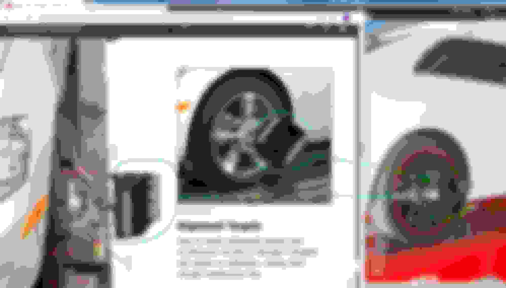
Something you guys in USA can be jelous of this time . Usualy I am jelous of your much cheaper car prices and the ability to get-whatever you-want options ....
It cost me only US$15 for 4 wheel alignment check on Hunter latest 4 wheels/ 4 cameras : HUNTER Hawkeye Elite Win Align 4 Camera - HE421CM
Last edited by S-Prihadi; 08-24-2020 at 02:17 PM.
Reason: typo
Yes I see what happened on the bushing pre-tension. Can the bolt be loosened then tightened while the car is on the rack since its resting on its own weight (suspension loaded)? Maybe I misunderstood but it seems you are doing the bolt work away from the rack.
Yes I see what happened on the bushing pre-tension. Can the bolt be loosened then tightened while the car is on the rack since its resting on its own weight (suspension loaded)? Maybe I misunderstood but it seems you are doing the bolt work away from the rack.
Need to remove entire swaybar to torque the CASTER nut. , hence I take my sweet time doing it at home and not at alignment shop.
I actually like doing the physical work myself. Its my own way of exercising LOL
I have experimented with various tools , no can't do for torquing if sway bar still in place.
Last edited by S-Prihadi; 08-24-2020 at 09:48 PM.
Reason: add photo
I managed to swap correction bolts orientation of use.
Monday will be the D-Day to see if MB WIS is a screw-up , when I get my alignment done for the 7th time or 3rd time in conjuction with Camber and Caster correction bolts adventure.
CAMBER, LEFT-WHEEL
CASTER - RIGHT WHEEL
Side note :
I found this video about Torquing a fasterner and why there is angle value after Newton value.
The video is so easy to understand as it is explained so well. I googled a few times already concerning why 180 degrees as 2nd stage after torquing 100 Nm ?...........and only yesterday I found it. Yipee !!!
So today Sunday I took the car out to test and do undercarriage washing.
As expected, the 28-30th Aug correction made will result in opposite reaction of steering angle error caused by 18th and 24th Aug camber + caster bolts wrong orientation. LOL.
.
What I do not expect is, it seems beyond 20 ish degrees of steering wheel off axis to a car straight line, the car computer seems to verify this problem condition by counting wheel rotation pulses.
The warning code it throws is obvious that LEFT wheel is assumed correct based on steering angle sensor of a left turn ( meaning inner tire rotation is slower than outer tire) and
hence computers telling me 3 other wheels rotation speed is INCORRECT , because they are equal to the LEFT wheel, where supposedly they should NOT be equal. That's my theory
The car feel like double shi-et , much worse than 24th Aug where it was worst.
This is because I also was playing around doing pre-load on all arms + bushing of rear axle, the toe of rear wheel I know I messed it up to some extend while at it...
This is VERY interesting experience on getting to know how the car wheel sensors algorithm works...awesome !!!
One tech tip.
On 24th Aug,during alignment. Techy engaged my parking brake which I did not realize when I reversed the car from the alignment rack and parked it somewhere else because few cars
are already queing up for alignment work. Funny, reverse prosimity sensor seems to by by-passed when car is in reverse but parking brake engaged.
Techy only engaged 2 clicks at the most and my car needs 4-5 clicks of hand brake engagement to really bite. So I wasn't feeling any resistance when reversing...dumb me !! LOL.
I only realized this because when I reversed very close to a fence, the fence has some lower portion concrete block protruding out way more forward than the fence.
So I minor hit that concrete block without even knowing till I move forward to depart for home, I sense a slight scratch sound from the back.... LOL.
There then I realized the reverse parking sensor was not functioning when parking brake light showed on dashboard.
Let see tomorrow 7th alignment result.
Last edited by S-Prihadi; 08-30-2020 at 12:31 PM.
Reason: typo
I forgot about that possibility of ecu fault if the steering wheel is turned but the road wheel are going "straight". Steering angle sensor not correlating with wheel sensor counts. Off-hand I don't remember count discrepancy allowance but I believe it's a fairly narrow window. I wonder if any traction control is being activated via individual wheel abs braking to attempt to correct.
Your steering wheel correction is as you showed pretty significant. Reminds me of my first car lol.
Very interested to see your alignment results - the car has been over to the right and now to the left so I anticipate there would be ample available center position (aligned).
Thanks for the effort you've put into this.
So, I did the 7th alignment today.
Please ignore the "BEFORE" REAR LEFT toe, I was on purpose loosening it for pre-load and for experiment to see how the adjustment is made.
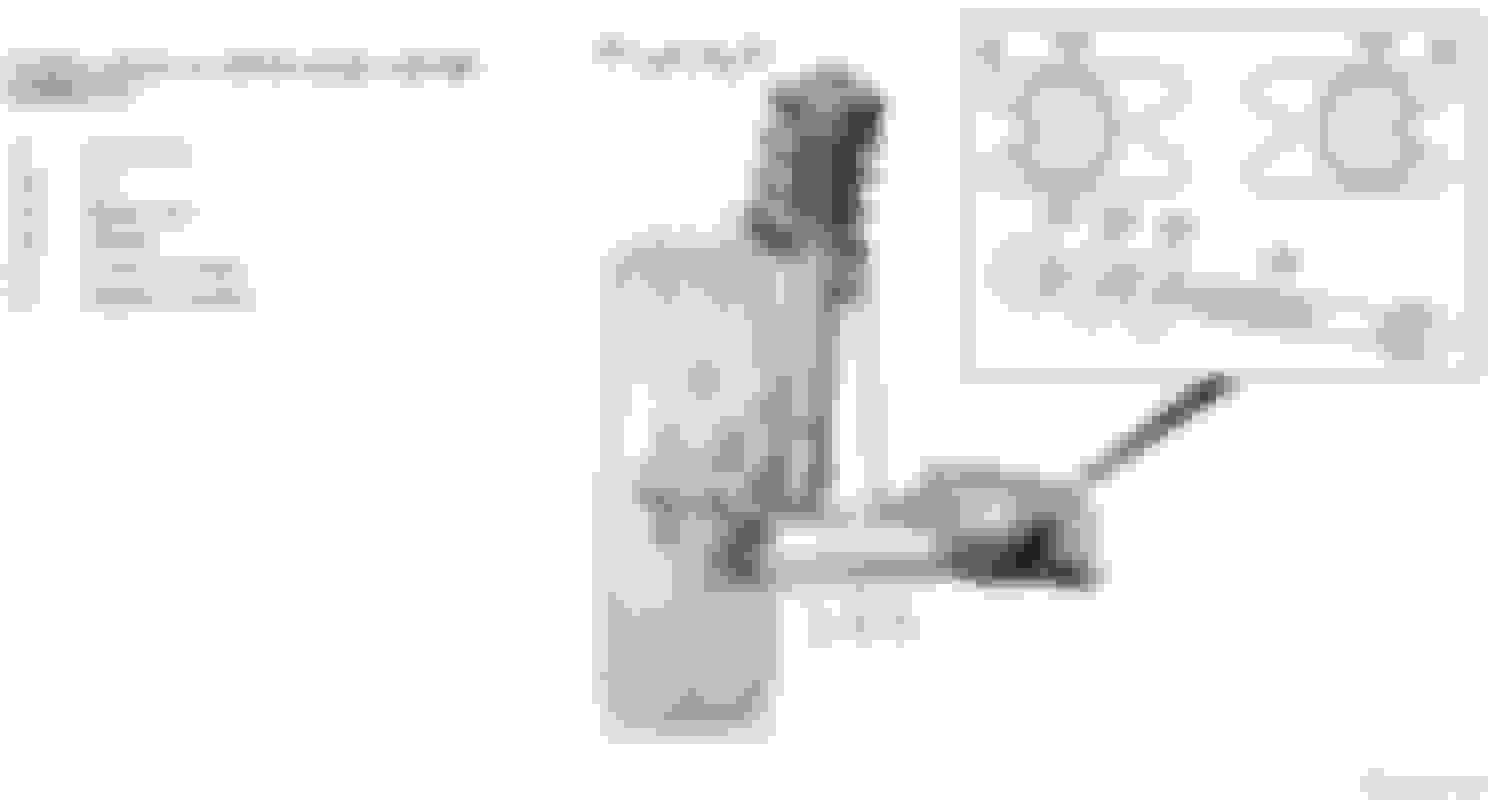
Yes yes yes...MB WIS AR40.20-P-0263EW - Adjust camber and caster at the front axle - 28.02.2018
is only correct for 1 side of the wheel, which is if for CASTER, it is LEFT wheel and for CAMBER is the RIGHT wheel.
Technically MB WIS is not wrong entirely, because it DID only show image of RIGHT wheel P40.20-2312-06 for Camber correction info. Right wheel as viewed from car front to rear.
The steering tie rod + ball joint is the give-away that image P40.20-2312-06 is a RIGHT wheel side.
However, the image of LEFT wheel P40.20-2434-06 ( brake caliper and caster rod position is the give away ) as illustration for Caster correction is wrong, if from the bolt head is what is read as
bolt's groove reference , and it is correct if seen from NUT view with end of bolt in viewer's eye. LOL.
However the writing is wrong at : Box 3 ... because there is no mention of LEFT or RIGHT wheel these method applies to and that simply means for BOTH wheels...correct ? Replace threaded connection of cross strut (17) on front axle carrier with repair bolt (19c) with washers (19d) and nuts (19b)
For Camber Correction : Pay attention to installation position of repair bolt (19c): Positive camber change (a) Negative camber change (b)
The same goes for Box 4 - The Caster correction thingy
Anyway, no worry. Education need sacrifice
Easier view, ignoring 5th and 6th alignment, we go direct from 4th >>> 7th alignment.
What is my next move ?
I will remove correction bolt of LEFT caster and install original non-correction one.
From there let see how.
If I look back at the abuse of 20 laps at the track with 9 right corners and only 2 of left corners to the suspension system, simplified view is below.
The comments I made is my own speculation as to why the 3rd alignment AFTER numbers are that way ....
So what will next suspect be ? Assuming changing back LEFT Caster bolt to original one does not produce the result expected ?
The adventure MAY continue.....
So, 8th alignment today. REMOVE LEFT CASTER BOLT to make values within MB spec.
8th alignment or 4th alignment for camber + caster adventure
What I learned so far :
01. For Front Caster, the value of the correction bolt seems 1.x degree and not 20' ( minutes ) or 0.3 degrees like what I read online .
But this does make sense in some way, though not entirely.
Make sense as in : value of Caster is 6* 57' as reccomended. So 1.x degrees of correction from the correction bolt does make sense. Approx 1/7th correction value.
Does not make sense as in : allowable differences between L and R caster is only +-30' and deviation from optimum of 6" 57' is also 30' , this 30' is 0.5 degree.
So that means one has to correct both side caster/s and wait till caster is out of spec at least 1* ( 1 full degree ) before proceeding, otherwise user will come to some problem getting the close to perfect value for both.
Surely changing caster arm or/and complete front damper or/and the front damper rubber top mount could be the other solution/s.
02A. For Front Camber, me a bit confused because my LEFT addition of correction bolt ( 4th to 7th alignment ) only added 6' ( 24' to 30" ) for AFTER to AFTER,
while addition of correction bolt for RIGHT camber gets massive 24' ( 18' to 42' ). 7th alignment is where all 4 correction bolts are installed, so whatever changes should be similar between LEFT and RIGHT wheel.
02B. What I want to learn is the correlation between CAMBER correction bolt/s and its effect to CASTER value.
In my 4th and 8th AFTER to AFTER for LEFT CASTER ( blue line & circle I marked ), from 6* 15' I get to 6* 37' or 22' positive increase of CASTER from CAMBER correction bolt, Left Caster correction bolt already removed at 8th alignment.
03. I am beginning to wonder, how is the repeatability of a 4 wheel alignment machine where the installation of the reflectors on the wheel is a generic clamp ones from Hunter and
not with the "five prong" MB specific adapter. Anyway my BBS wheel no more has that 5 mini holes for MB specific alignment reflector mounting adapter.
My original Ronald AMG has the 5 mini holes for alignment reflector mounting adapter.
To those not familiar with MB five prong alignment reflector mounting adapter, what I read is that, this MB specific adaptor is to make sure alignment machine read from the wheel hub and not
rim/wheel or tires because rim may be out of tolerance due to pot holes. It does make sense for maximum accuracy to use this MB approach. If I remember correctly, BMW also has those 5 mini holes on their original rims.
If we ask a machinist doing super low tolerance measuring, I bet they would want to buy super flat surface like this >>> https://www.grainger.com/product/STA...ers-Flat-6PDF3
That got me thinking, all the What-If ?
If anyone here is very **** on how to use a Mitutoyo digital venier caliper properly, you surely must have read that a caliper does not conform to Abbe�s Principle, rule of alignment.
Page 23 of PDF numbering https://www.mitutoyo.com/wp-content/...QuickGuide.pdf
I think one need to ask Hunter, how do they guarantee that their reflectors can actually sit well at all time with 99.9% repeatability.
I do not see any zero-ing protocol for rear wheel, only front wheel where the techy turn it left and right...which I assume this tells Hunter machine the zero for front wheels , at least for toe.
How about camber, that optimum value of 33' or only 0.55 degrees.... wow, such insanely small value. How to get repeatability measuring this value with something as simple as a clamp on adapter ?
Will update 9th alignment soon, where I will REMOVE the RIGHT wheel Caster correction bolt.
When all values reached to my liking, I will find another 4 wheel alignment machine, if possible from other brand, as 2nd opinion/measurement. I am very curious.
Season Finale .........
The "villain" is finally dead.
So what have I learned ?
.
More analysis - Front suspension/alignment
.
More analysis - REAR suspension/alignment
.
Tips for those wanting to do Caster/Camber correction bolts.
Start with CAMBER first, assuming your camber is off the spec while all arms, bushings , sway bar links ( ball joints) , lower and middle ball joints and all 4 dampers are still decently healthy.
Do not make the same mistake as I did. Correction bolts for camber in MB WIS is only correct for RIGHT SIDE WHEEL and you must do the opposite of the instruction/advice for LEFT SIDE WHEEL.
Camber, right side wheel :
Camber - Left side wheel:
The same problem with CASTER correction bolt, but MB WIS is wrong for Right Side wheel this time.
Remember, correction bolts only do 2 things : PUSH or PULL of the arm/wheel.
Since Left and Right side wheel is different in orientation towards middle of the car or the sub-frame, MB WIS must produce DIFFERENT instructions for both LEFT and RIGHT wheels.
This has been 40 over days of fun & learning.
I learned a lot.
So this post continuation maybe only when I find another 4 wheel alignment machine, but not from HUNTER.
Its tough, Hunter dominate the Indonesian 4 wheel alignment machine. Other european brands sold in Indonesia, are 99% front wheel alignment only.
There is one from a China brand, I don't know what brand, but it is supposedly a 4 wheel alignment machine.
However, I want to stick to only a brand with long term reputation and has one of more of their 4 wheel alignment machines approved by MB.
Let MB does all the verifying.
Over n out.
Last edited by S-Prihadi; 09-05-2020 at 03:57 AM.
Reason: Add image
Really well done, especially to follow up through cause/effect and a final solution.
I hope the site will put this up as a tech sticky as it details so many of the suspension parts and alignment criteria.
Mud,
I think MB WIS expects that a techy goes to MB Alignment school too. The WIS itself is like a mild refresher.
So techy will understand to do opposite of WIS in regards to correction bolt head groove orientation, that A or B and C or D... where applicable, once techy understood the concept of the correction bolt/s.
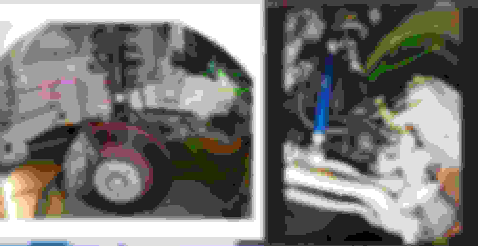
For others. Some tip if I may :
For those working alone ( or with limited help of a buddy ) and/or with limited working height due to not having access to a full height workshop car lift, when doing stage 2 tightening of the NUT at 180 degrees spin after 100Nm,
see below photo to assist yourself in making sure an angled wrench sits well on the NUT and not slipping. 180 degrees after 100NM is a lot of force, I think 200 NM or more. Surely above 180Nm. So wrench slipping unless
you have good working space, is a high possibility. Yes, a pipe is a must for extension for the wrench, unless you are crazy strong able to do 200 Nm with a single hand while lying on your back on the floor.
Since my wrench is a 40 degrees offset one, when I tighten a nut with a long pipe assist, due to that 40 degrees offset ...... the wrench head can slip easily from the NUT, unless I use another nut to lock the wrench head in place.
At massive newton value an angled tool is not friendly for us working with limited height under the car. Without the extra locking nut holding the wrench head, I need an extra hand to push the wrench head tight against the nut manually by hand.
If the wrench is not an angled/offset one, that "lip" of the subframe is kinda get in our way.
So what can beyond 180 Nm do to a crow foot wrench size 21 ? Maybe my tool metal is not the greatest, but 2 pinch points tool is always never a good idea for high power torque nut tightening.
The crow foot wrench slipped and kinda damaged....LOL. I was itchy handed trying to see what newton value is 180 degrees after 100NM. 190NM only gets me no more than 120-130 degrees.... when the crow foot wrench got damaged.
Happy pumping iron ....
Last edited by S-Prihadi; 09-05-2020 at 07:46 PM.
Reason: add image
 08-18-2020, 04:40 AM


 .... something is way OFF, more than just a TOE value being OFF.