When you click on links to various merchants on this site and make a purchase, this can result in this site earning a commission. Affiliate programs and affiliations include, but are not limited to, the eBay Partner Network.
2016 E350 4Matic wagon, 2019 Ford Expedition, 2019 Chevy Bolt EV
Originally Posted by bmwpowere36m3
Its interesting the topic of the high current transients... as far I know, there's nothing in place in traditional VRs to limit current. The only limit is the batteries internal resistance, plus the resistance of the circuit (wiring/body). I akin it to flipping a switch or current draw during an electric motor start... Additionally, AGMs typically have lower internal resistance than flooded lead-acid
Is this worse than a few second draw at 150A+ during a start?
indeed, the current is a function of the voltage and impedance/resistance
a 'smart' battery charger, the bulk stage outputs whatever voltage keeps the current at its max allowable value until that voltage hits about 14.2 or so V, then it holds that voltage while the current decreases as the battery further charges, so the first stage is constant current rising voltage, and the second stage is constant voltage, falling current. a 3 stage charger then does an absorption stage at around 14.4-14.6V, sometimes even as high as 15V, for a fixed period of time based on how long the second stage took.
I also have smart charging on Sprinter, who doesn't have ECO option, but does have 250 amp alternator.
When I have no easy way to measure charging amps, I doubt they are high. Usually after morning start the system will operate for few miles at 14.4V, than it will drop to 13.3-13.5V and stay like that for most of the day.
Observing voltage fluctuation on sedan with ECO, is like "hold my beer and watch this" but it seems undercharged all the time and on following day the ECO will not work for several miles.
Occasionally I hook up battery maintainer and then ECO will work once the engine reaches 60C, so short drive.
Yep, the moody "ECO" you describe is what raised my suspicion in the first place.
It would work ok on floated battery otherwise without any floating, ECO was flaky.
So I figured the battery charge was in question and saw how the more I drove, the lower the charge got...🤔
Do you observe the same thing?
Last edited by CaliBenzDriver; May 1, 2021 at 03:53 PM.
2016 E350 4Matic wagon, 2019 Ford Expedition, 2019 Chevy Bolt EV
Originally Posted by kajtek1
I also have smart charging on Sprinter, who doesn't have ECO option, but does have 250 amp alternator.
When I have no easy way to measure charging amps, I doubt they are high. Usually after morning start the system will operate for few miles at 14.4V, than it will drop to 13.3-13.5V and stay like that for most of the day.
Observing voltage fluctuation on sedan with ECO, is like "hold my beer and watch this" but it seems undercharged all the time and on following day the ECO will not work for several miles.
Occasionally I hook up battery maintainer and then ECO will work once the engine reaches 60C, so short drive.
a start that only takes a few seconds of cranking isn't going to pull more than a few % of the battery down, so will recharge quite quickly.
if you were to accidentally run the battery down say 50% (~12.0V at 68F/20C), then start the engine, I bet you'd see those 14.4V for a significantly longer interval.
My engines start on 1st turn, so I don't think the battery gets discharged any significant %, but for some reason the Sprinter smart charging keeps the higher charging for longer time.
That is not happening on the sedan, so there are different kinds of smartest.
Took a 65 mile drive yesterday. The only time I saw battery drain was when the engine was off. Volts while engine on never went below 14.5. After the initial recharge after starting, the battery saw a current input of about 1.5 amps for the rest of the drive.
Everything works.
I recorded the below for starting my S550. Battery voltage at 11.9V, starts just fine. Voltage goes up to 14.6V a few seconds after engine runs but when I went to drive the voltage was at 12.6 at all times other than when I slowed down. Drove only about 15 miles though.
Current was most of the time around 1 - 1.5A other than right after engine start it went to over 70A.
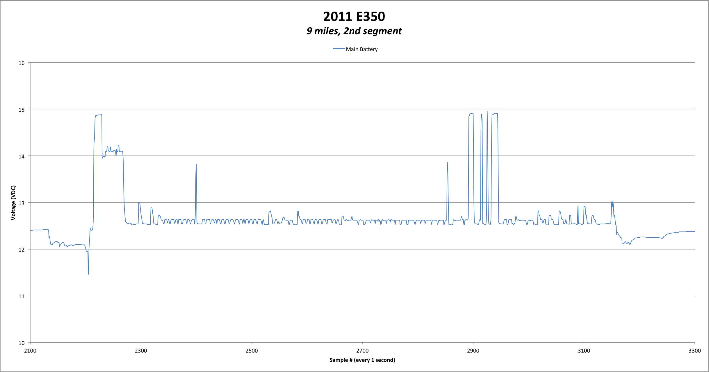
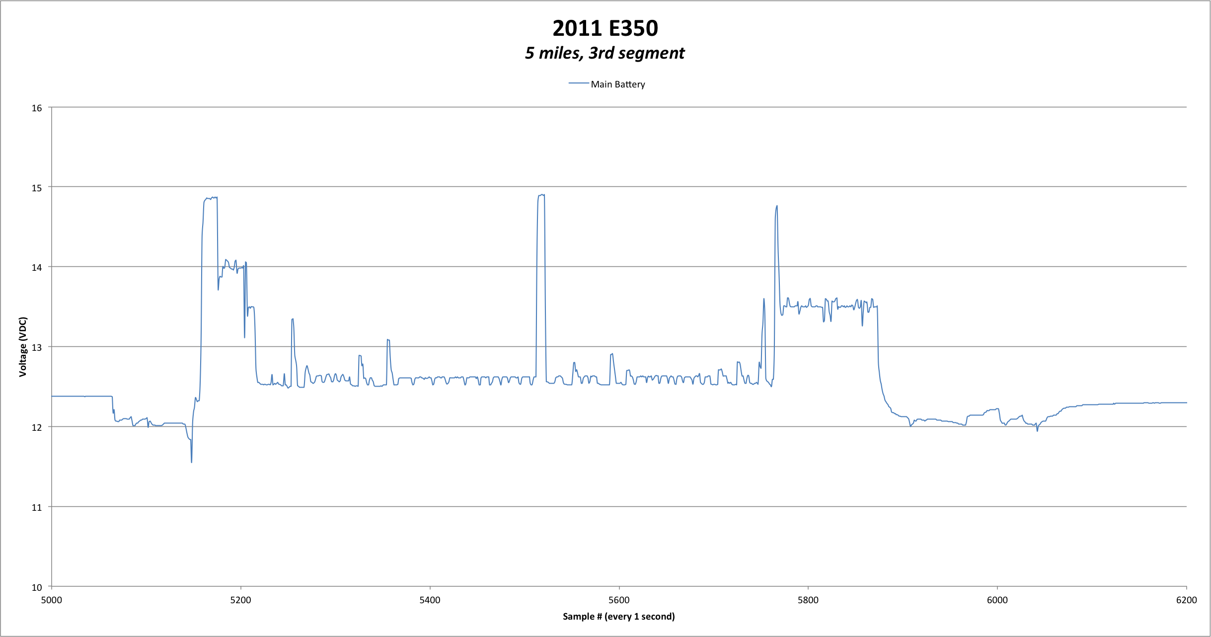
Took the '11 E350 wagon for a short trip, ~30 miles with 2 stops. The wife mainly uses the car, mostly all short tripping. Connected a data-logging DMM to the jump terminals under the hood and the results are:
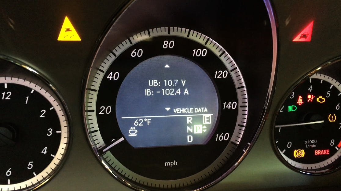
During startup I recorded the vehicle data screen under the workshop menu. First start cold, peak draw 102.4 A and 10.7 V.
Charging occurs right after engine start, it ramps up and then down to ~ 5-6 A quickly. After ~10 seconds [after engine start] alternate ramps up charging again. It peaked at 48.3 A and dropped to ~16 A after the first minute.
Lastly, while cruising on the highway I noted the car maintaining ~12.6 VDC... switching from drawing 4-6 A to charging 4-6 A, back and forth. I thought I recorded, I guess I didn't... but you can see the square-wave pattern around 12.6 in the plots.
Thank you for this nice battery instrumentation. It serves as baseline of what things should look like during a drive cycle.
healthy voltage control
- The "quick charge" stage being short is a positive sign the ECU logic is satisfied with the AGM charge.
- The voltage regulation is rapidly yielded over to ALT under 12.6v maintenance float during most of the driving cycle.
- 14.9v bursts add free opportunistic charge
- Load demands are met with responsive 13.5v pulses to prevent unwanted deeps.
- No discharge swings are observed while driving.
> Textbook perfect system reference 👏
----- edits: RIPPLES...
The 4-6A back and fourth you observed may be what is creating the 100mV ripple pattern over 12.6V. It looks like that's how ALT logic does its float regulation with ON/OFF pulses.
It's always eye opening to look at the reality of things and discover new bits: ripples over 12.6DC.
---- edits: AirCon load reg.
The data show how the AirCon load (or headlights) trigger a voltage bump to 13.5V. In turn this voltage does keep charging AGM slowly all the way to max and into hydrogen producing region.
At some point the ECU logic also does quit bursting 14.9V pulses.
Last edited by CaliBenzDriver; May 4, 2021 at 02:04 PM.
Reason: formatting - 5A riples - A/C load
Okey, here we go again.
These facts below I need to verify, any assistance will be nice.
01. OBD2 port has pin #16 as +12V.
So I assumed that what the Torque App via the bluetooth dongle called OBDLink LX called VOLTS (Ad) or voltage of OBD, is this #16.
So this is an analog voltage converted by the OBDLink LX to be read/recorded by the Torque Apps.
02. The so called VOLTS (CM) or control module is part of OBD2 standard. PID HEX 42 PID dec 66 Control module voltage
So this is a digital data sent out by the ECM ( ECM I assumed is the control module ) on the OBD2 data highway.
03. MB own voltage and amperage data at instrument cluster comes from Hyundai Mobis. This small shunt/sensor is at the battery negative post.
The question is, where does this information takes the positive feed from ? I am assuming it takes the +12V as close as possible to battery post and it maybe the F32 prefuse block or the pyro fuse at the positive battery terminal. Guys ?
If I am correct here, that means the instrument cluster data is the most upstream voltage condition and not yet effected by sudden spike of local low voltage ( voltage drop ) downstream or may not even be effected by voltage drop downstream up to a point.
My last excel file log on charging, the parameter I chose was VOLTS (CM) or control module. Many of you expressed concern on how the voltage can be so low ? I agree, that caused me to re-think.
2nd May 2021 Sunday I did another test and this time I read VOLTS (CM) or control module and VOLTS (Ad) voltage of the OBD2 port and surely the car voltage and amperage display. All at the same time but in a video logging.
At the same time, I also logged the 2 freon pipes exterior temperature of my A/Cond system for curiosity sake, as my curiosity was triggered by CaliBenz https://mbworld.org/forums/e-class-w...nder-5-4u.html
Why I need to do 3 voltage sources reading ? Simple, this car is separated into a few electrical zones and local low voltage can happen. Imagine a big building with many electrical sub-panels handling various loads in various rooms/area.
Reading voltage at the incoming utility/main can not tell the truth if the troubleshooting does not go to the most distant electrical sub-panel and read voltage drop at the load/s itself.
So yes, I am shifting my focus to potential downstream/elsewhere voltage drop, the excessive one. Since I can't do anything about how MB manages its charging algo, at the least I am hoping to understand better the voltage integrity
of the car at various zones ( sub-panel / SAM ). Since this car electronics can go banana when voltage dropped to a point, the more we know about voltage drop at highly loaded condition downstream of F32 pre-fuse, at hot temperature,
the better troubleshooter we can be, when and if the need arises. This also serves me itchy hands
NOTE : Torque App data has lag. From OBD2 port to bluetooth version OBDLink LX , probably 0.5 second lag is expected.
Anyhow what goes on was logged, but the timing towards the car voltage + amp display may not be sync to 0.1 second resolution.
VOLTS (CM) or control module and VOLTS (Ad) voltage of the OBD2 port
ABOVE : I am not suprised that even if battery voltage is at 12.8V read by Hyundai Mobis, while the battery get discharged at -40.3 amps and then Control Module voltage swing down to 12.1V for under 1 second.
Typical engine management I tested at approx 31 amps while car stationary. Assuming 31 amps are handled by the same zone/SAM as Engine Control module, with the cable feed already hot after 46 minutes of running the car, and then Hyundai Mobis
only use battery voltage as reference and doing its DISCHARGING... the Control Module then get short voltage "starvation"
ABOVE : 36 seconds of discharge, swinging from 41 amps >> 30 ish amps >>> to 20 ish amps really made even the battery voltage at Hyundai Mobis down to 12.5V and Control Module from 12.1 - 12.2V too.
All screen captures above are not all that has 12.1 to 12.2 volts occuring at Command Module. To see them all, watch the video. Will need a video player ( if you download it ) which has good frame by frame viewing capability.
These are the reading points for the freon pipes external temperature. Choice of sensor location is about convenience. I do not understand HVAC well...yet
That terminal I clipped with DMM lead is the direct alternator output into F32 pre-fuse block
Sometime in the future, I will need to do another test where I can read the alternator GROSS output into F32 fuse block in real time while driving.
The hardware is in the works.
I did try on this 2nd May test to read amperage of alternator, it was supposedly rigged using a small UNI-T amperage clamp which I will place and clamp it at alternator wire before it enter F32 pre-fuse block and use camera to record with video light,
as I will close the hood to make it really like a stand still traffic simulation.....when I reached home. I gave it 10 minutes max, as to not damage those 3 hardware. All good, but I forgot to press record on the camera, DAMN DAMN DAMN, I only pressed ON to power the video light.
Okey dokey.... have fun doing "Autopsy" on the video.....for those wanting to explore more.
Last edited by S-Prihadi; May 4, 2021 at 06:59 AM.
Reason: remove double photos
This is a lot of instrumentation going on between: voltages, currents and A/C temps, your car may think its at the doctor's office getting an EKG. Thank you for wiring the beast - I really like your leather seat natural color 🙂
To answer you:
in our case the battery current is exactly the same on either side of it. The +/- notations denote incoming/outgoing ie. charge/discharge.
We see Hyundai sensor appears functional and trustworthy...
Here is the PDF datasheet of a leading alternator LIN CONTROLER chip by NXP giant ... a smart chip!
Benz Voltage Drops are a very interesting topic:
Where drops are... (preFuse, SAMs, wiring)
Why there are drops... (heavy loads into Res.)
What to do about drops... (dual regulation!)
There are zero drops involved with AGM charging (ALT control is driven directly by Hyundai voltage during charge)
Significant drops... are partially offset by higher voltage output for heavy consumer loads
Base load drops... I believe are offset by adaptations (ECU, tranny TCM,...)
At any rate voltage drops are known source of electrical issues (heat, oxidation,...)
The purpose of the Hyundai is to measure precisely what share of the alternator output current goes into AGM during "quick charge" stage. After that, the alternator is only used to supply the car with a constant voltage above discharge level with a consideration about consumers load.
I look forward to your interesting tests findings and conclusions.
For the sake of clarity let's try not mix "charging system" and "A/C temps", right??
----edits: 25mn video.
What I noted was:
- it took 45mn long to reach end of "Quick charge" under full voltage output
- voltage climbed down with moderate discharge
- With A/C:ON, the voltage should have stayed at or above 13.5V at all time.
- After driver door got opened once while parked: Voltage normally climbed into charge
- Car with A/C draws around 50Amps (55-5)
- Alternator responding well to ECU control is a good chance rectifier diodes are A1
--> To find solutions I tend to focus on gaps between reality vs. expectations.
Last edited by CaliBenzDriver; May 4, 2021 at 11:21 PM.
At any rate voltage drops are known source of electrical issues (heat, oxidation,...)
+
For the sake of clarity let's try not mix "charging system" and "A/C temps", right??
+
----edits: 25mn video.
What I noted was:
- With A/C:ON, the voltage should have stayed at or above 13.5V at all time.
.
Voltage drop another sure-thing-known cause is stingy cable size ... too small and also the 100C ambient engine bay temperature above V block is not helping.
This is based on the N3/10 aka ME-SFI [ME] control unit assumed as Control Module by OBD2 protocol.
The air-cond freon pipes temp is just for fun sake.... and as baseline, while already me spending 1+ hour testing the DC charging system.
With A/C:ON, the voltage should have stayed at or above 13.5V at all time.
Unfortunately that is not the case I am seeing. A/C is always ON for us tropical country, we will declare a car as not-useable if the A/C doesn't operate.
I am going to hunt down this voltage drop at the assumed Control Module aka N3/10 aka ME-SFI [ME] control unit.
Main positive feed using 0.75mm cable size is too small for such an important task N3/10 is responsible for. Such horrible above and in between the engine V block positioning too, there air temperature is easy 100C.
Adding insult to injury, the negative feed aka ground gets 1.5mm cable size.
V6 3.0 Turbo version for E400 called M276.820
Let see voltage drop.......... since the fuse is 7.5A for N3/10 , lets assume 5 amp is the norm. Let's do various engine bay operating ambient temperature.
We disregard wire ampacity rule which governs ampacity reduction value for wires bunch together and yada yada. We focus solely on engine bay operating temperature
Now, if only MB uses the same 1.5mm cable for positive feed, it won't be so miserable. Better yet DO NOT discharge the battery, simply do the : ZERO CHARGING , that is good enough.
See below, if I use 6 amps of load, that baby 0.75mm baby sized wire at 100C looses another 0.09 volt or 0.54V total, sad. If MB uses 1.5mm positive feed cable size , voltage drop at 6 amps 100C is only 0.27V which is decent.
This is as discharged as it should be for the algorithm.... ZER0 CHARGING , that will be sweet.
While at it , I think I am seeing how the ECO system is checking its small battery at the trunk or using/charging it for a bit maybe ?
The 16 seconds of ZERO CHARGING has unique data to it. Regardless that the Torque App has delay of easy 0.5 seconds, this 16 seconds of zero charging shows unique information.
The VOLTS (Ad) or OBD2 port pin #16 can be higher than the alternator in all screen capture 1 to 4.
- Are we seeing ECO's baby battery surface voltage ?
9 seconds ( I wrote in green , a +9 on screen capture ) into Zero Charging, screen capture no 3 .......... even the control module rised up to 13.4V and ODB2 port rised to 13.7V, while alternator is still at 12.8V.
AA. Where is the charging or raised voltage coming from ?
BB. Let's assumed we are seeing ECO 101 in action from the alternator doing stealth mission for baby ECO battery... LOL.
How is the alternator separating/isolating its output between main battery and ECO battery, in respect to where Hyundai Mobis positive feed sense wire location and reporting method for instrument cluster ?
There is a charging or parallel relay at the ECO battery in trunk yes... we know.
CC. VOLTS (CM) aka control module is from OBD2 protocol, that is MB's own produced "cooked-ready-to-use" digital data and not from Torque App, that should be a reliable value .
Wow... more mystery. I think Dan Brown was part of the MB ECO algorithm designer
... if you want to poke around modules for different sources of voltage other than the now trusted Hyundai, rearSAM does his own measurements., I think Ignition and steering too... many scattered modules collecting values non-trivial to correlate with our main thread topic here:
- What conditions create low battery.
You mention economy sized wiring... I believe some cables are even purposely designed with resistive alloys to provide short-circuit protections. We saw earlier why battery path should be resistive to promote equilibrium tilted in favor of alternator output.
Are you hinting that your car purposely discharging its main battery while driving is a normal feature? That's where I take a shortcut and directly tie this problem to some "exhausted batteries".
I've observed many times the same frozen Display showing 0.Amp for a couple seconds. It usually happens shortly after starting. It's weird! 🤔
Your ODB2 data display confirms similar voltage (+/-refresh lag) perhaps from the exact same source too 🙂
Last edited by CaliBenzDriver; May 5, 2021 at 12:35 PM.
Ha ha ha...........
01. I know what's going on when the so called ZERO CHARGING / DISCHARGING event takes place.
02. Now I know how below can happen :
9 seconds ( I wrote in green , a +9 on screen capture ) into Zero Charging, screen capture no 3 .......... even the control module rised up to 13.4V and ODB2 port rised to 13.7V, while alternator is still at 12.8V. AA. Where is the charging or raised voltage coming from ?
BB. Let's assumed we are seeing ECO 101 in action from the alternator doing stealth mission for baby ECO battery... LOL. How is the alternator separating/isolating its output between main battery and ECO battery, in respect to where Hyundai Mobis positive feed sense wire location and reporting method for instrument cluster ? There is a charging or parallel relay at the ECO battery in trunk yes... we know.
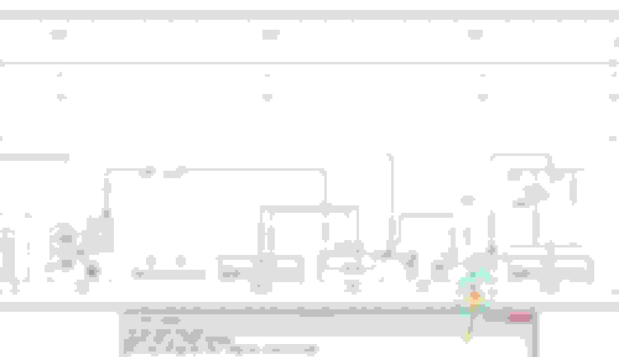
For B03 ECO start-stop option vehicle, MB placed a RELAY-DIODE COMBO , when and if needed....to kind of isolate G1-Main Battery at engine bay from being charged by G2-Alternator, where G1/13-ECo Trunk 12Ah Battery still can get charged.
This RELAY-DIODE COMBO is called V19 Eco Start/Stop Function Diode ( V19 for automatic transmission, manual transmission gets K19/7 relay )
This relay resides in F32 pre-fuse.
V19 relay is similar to how MB isolate 30g circuit. 30g is a circuit which will shut down after a designed period of time or a SWITCHED positive.
The relay for 30g is called K2 or F32K2 which means K2 relay inside F32 pre-fuse.
As with all mechanical relays, the contact points will degrade, arc, poor contact, build up carbon and resistance ............ when it has been used enough.
Not including the total or partial failure of the energizing coil to latch this relay. Anyone who has machineries operated by contactors would know what I mean. Relay=Contactors, same same.
So, a B03 ECO Start Stop car with V19 , now has 2 failure points to watch out for..., not only the 30g K2.
So, the 16 seconds of ZERO CHARGING - DISCHARGE is the ECO algo doing its health check for the trunk ECO battery and at the same time charging it a bit.
See below...... I re-drawn the V19 to make it simple to understand. M1 is starter. N2/10 is rear SAM. F63 is Pyrofuse. G1 is primary battery at engine bay. G2 is alternator. N10/1 is Front SAM. What is not shown is Hyundai Battery Sensor B95, which we all know is at Battery Negative Post ( G1 )
During the 16 seconds, V19 Relay does not latch so it is open circuit. However, it has a diode as 1 way electron valve to supply F32 main bus bar if needed, so basically G1-Main battery is it always being sucked by
F32 main bus bar if alternator doesn't provide higher voltage. V19 has no true disconnect from F32 bus bar with such a diode in place, one way flow disconnect yes, but not both way-flow disconnect. So the following happened :
AA. When V19 relay in open circuit, Hyundai Battery sensor B95 shows Zero Charging-Discharge, voltage stay decent from 12.9V down to 12.8V. 12.9V is probably surface voltage and 12.8V is the assumed-fully-charged
battery voltage stabilizing. Be reminded again, at this point in time G1 is not (can not) be charged by the alternator.
BB. G1-Primary Bat due to diode having forward voltage drop, and the alternator (G2 ) which is now pumping out power and higher voltage than 12.8V , alternator then carry almost all, if not 100% all of the electrical load of F32 bus bar by virtue of higher voltage potential difference. Here the G1/13 which is ECO battery 12Ah at the trunk get charged, because K114 relay closed. V19 relay section is open circuit, G1-Primary battery can not get charged because diode is blocking. See below :
So during the 16 seconds of Hyundai Mobis battery sensor B95 showing Zero Charging-Discharging, unknown to us/me due to no shunt/sensor at ECO Bat G1/13 , this baby ECO battery is getting charged.
Hence we see voltage rise at Control Module Volts(CM) and and OBD2 port Volts(Ad) in Torque App. Control Module Volts(CM) is from N10/1 front SAM in digital form as part of OBD2 protocol.
OBD2 port Volts(Ad) analog voltage pin #16 which MB called it as X11/4 Diagnostic Connector, is fed by N10/2 Rear SAM and protected with a 5 amp fuse. See below : Holy Crap, don't ever mess with pin #9 !!
Now below, we shall see B95 Hyundai battery sensor finally indicated in a schematic and it is managed by N10/2 Rea SAM, coz baby ECO battery G1/13 is afterall at the trunk and is the receipient of G2 Alternator power injection,
so rear SAM controlling or reading B95 make so much sense.
A bit of RANT first please.
I hate that my car model is 212.065 with 276.820 engine ......as far as WIS/EPC is concerned* ( *owning + driving it I love it ) , this is a "Paria" model made to be murdered fast, as W213 was coming soon.
WIS/EPC is so difficult to use when often my M276 3.0 TT is confused with M276 3.5 NA , even by MB EPC/WIS writer or organizer.
At times EPC/WIS is kind enough to write valid only for 276.8xx , at times it called my engine 276 M002 ... WTF ????
With worldwide option on MB W212 is so long, reading F32 schematic alone is a waste of time removing items which is not on my car ... LOL..
N10/1 Front SAM is a nightmare to read for the in-experienced me
Okey back to business.....
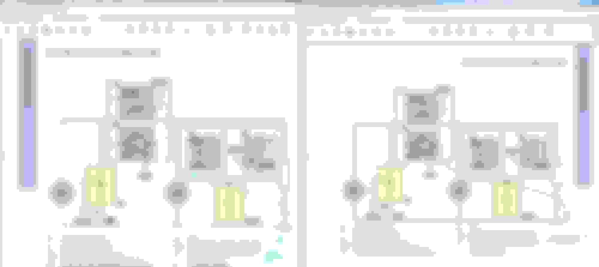
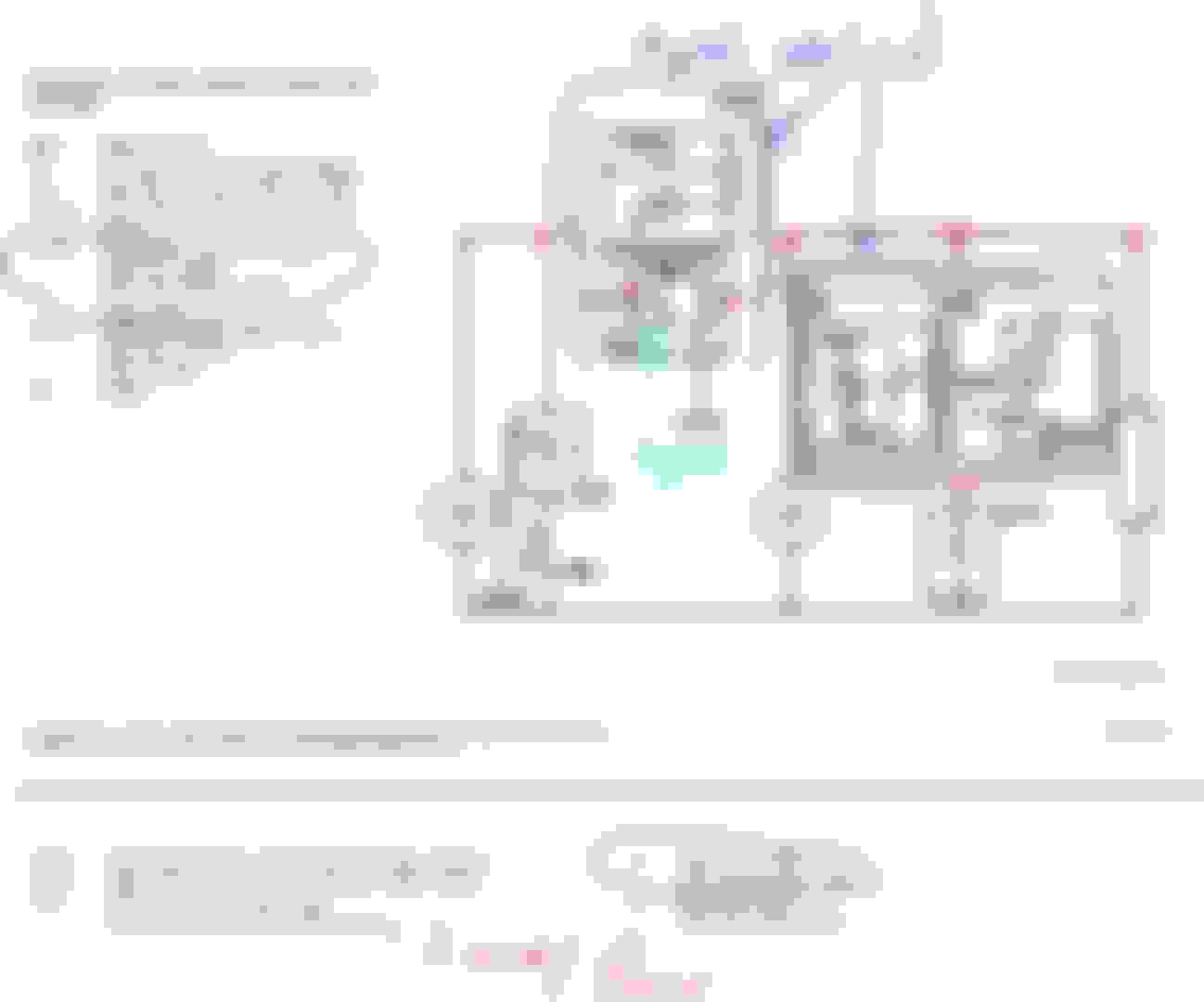
Here is F32, my version ... but still some data doesn't match F32 wiring.
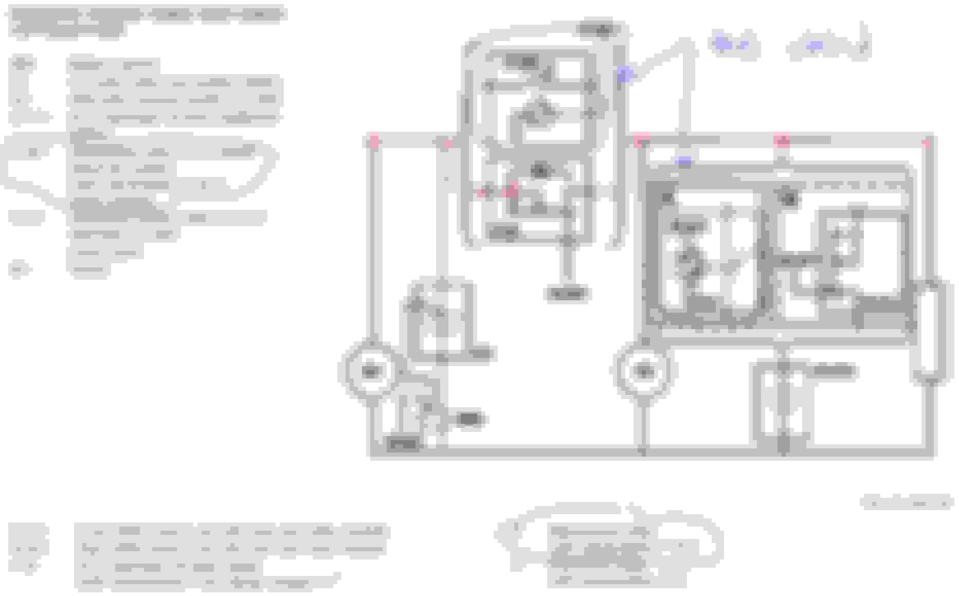
Here is what the F32 original schematic looks like if not made easier to understand about the V19. Below:
From ECO Technology Guide , yet they still make mistake
I touch up a bit, for my car model and also for easier view. The illustrator is so stingy with V19 relay side opening.... LOL
So what's next to test ?
01. Get alternator GROSS amperage at F32 pre-fuse box prior to connection at MR8 terminal. Must use shunt.
02. Get amperage traffic at G1/13 Eco Bat negative cable to ground. Can use amperage clamp.
03. Get voltage data at G1/13 Eco Battery post.
Brilliant grand tour, this is awesome - Thank youuuu 👍👍👍 The ghosts know they have no place to hide in your car.
Now we know about the "0.0" display plus we have a newly recognized failure-point in the F33K2 relay that disconnects no less than Main battery itself! Wonder what could go wrong...LOL 😅
How many time can that relay eat 80...60Amps?
1K, 5k, 10k cycles?
Less charge Amps= long life guaranteed.
High Amps > HighDropVolt > high heat > fried!!
---- Edits: MOSFET transistor switches (upgrade!)
As far as I understand here... with ECO option and the 722 automatic AUX gets charged through an electronic transistor instead of a clunky on/off SPST relay still in production for other option packages.
This updated switch allows the Charge Voltage to be ramped up smoothly the way we like it, to keep Charge Current well under control. (the bad way is unlimited current observed with front AGM ...🤜 80Amps - lol)
Last edited by CaliBenzDriver; May 6, 2021 at 09:24 PM.
Sounds like you had a lemon that MB would not help with. That is not the same thing as a poorly designed system. I am also primarily a highway driver, and have never had any such issue. Same car, same systems.
Glad you got rid of your problem car, but that does not mean all W212s are the same. As a matter of fact, it almost seems like no W212s are the same.
I just wanted to add to this -- I had 3(!) loaner W212s which also had battery failures. 2x 2015's, 1x 2016. So it's not an isolated incident.
I also had a few loaners with the same AC issue I had, wherein the car would be cooling then suddenly would go to full heat for a minute or so then back to cooling...even if it's 98F+ outside.
So now I'm wondering if the non-eco models use the same system to charge the small in-dash battery.
Give me you VIN so that the WIS can be linked to the correct model designation. General W212 F32 does not show the dashboard small battery, I think it is controlled by front SAM N10/1 and not F32 due to super small size it is.
I just wanted to add to this -- I had 3(!) loaner W212s which also had battery failures. 2x 2015's, 1x 2016. So it's not an isolated incident.
I also had a few loaners with the same AC issue I had, wherein the car would be cooling then suddenly would go to full heat for a minute or so then back to cooling...even if it's 98F+ outside.
Had the same on my W211 who had 4-zones.
Later only discovered that dog, resting his front legs on rear control panel adjusted 1 zone to max heat.
Now we know about the "0.0" display plus we have a newly recognized failure-point in the F33K2 relay that disconnects no less than Main battery itself! Wonder what could go wrong...LOL 😅
---- Edits later...
K2 relay of F32 pre fuse block will eventually be a problem on older car, but since MB does not sell it separately , one must buy complete F32 fuse block.
This article below talked about it... W212 of 2011 to 2012 so it claimed. https://garagewire.co.uk/news/compan...-design-fault/
Looking at the assigned duty for K2 providing the 30g circuit, if the relay contact starting to go bad but not yet total loss, it will be not so fun to troubleshoot as one must load up high amperage to find out.
So now I'm wondering if the non-eco models use the same system to charge the small in-dash battery.
Aha.... this small baby battery is not managed by N10/1 Front SAM
MB called this small baby battery as G1/7.
15watt charge is a lot for a 1.2Ah ( 14.4 watt ) battery. But since 15 watts is small, the N73 module probably can have built in switching device to charge as needed and not a dummy always ON charge. CORRECTION : The charging can not come from N73, N73 is the consumer. By logic of the diode for G1/7, the charging has to come from N10/1 front SAM but the schematic is missing the wiring specific to charging. The diode is to prevent during engine crank, so that G1/7 to NOT parallel with G1-Main Battery. Someday I will figure it out yah.
Find 3 attachments...
Have fun reading.
Last edited by S-Prihadi; May 6, 2021 at 09:05 PM.
Reason: wrong info
I just wanted to add to this -- I had 3(!) loaner W212s which also had battery failures. 2x 2015's, 1x 2016. So it's not an isolated incident.
I also had a few loaners with the same AC issue I had, wherein the car would be cooling then suddenly would go to full heat for a minute or so then back to cooling...even if it's 98F+ outside.
It looks kike you were on the receiving end of this problem, unaware all along what caused this giant waste of time and money.
comfort load shedding
The A/C you observed acting up may well be a direct consequence of consumers load shedding. R-SAM can order reduction of both Blower and Fan to 50% (plus RearDefroster, seat heaters...) when voltage deeps lower than 12.2V
Did you experience any sudden "Limp-modes" or "Christmas trees" while driving with low voltage issues?
K2 relay of F32 pre fuse block will eventually be a problem (on older car,) but since MB does not sell it separately , one must buy complete F32 fuse block.
This article below talked about it... W212 of 2011 to 2012 so it claimed. https://garagewire.co.uk/news/compan...-design-fault/
Looking at the assigned duty for K2 providing the 30g circuit, if the relay contact starting to go bad but not yet total loss, it will be not so fun to troubleshoot as one must load up high amperage to find out.
reality from the trenches
Great find from the UK industry press!
The K2 relay that disconnects the main battery causes cars to quit when it had enough abuse.
That's a good reason for not ignoring the 80Amps conundrum highlighted throughout this thread.
Low batteries are only the tip of the iceberg. Replacing them is far from a cure all fix if your car is affected.
Floating does help by normalizing the charge current during "quick charge" cycle.
Unaffected cars will benefit minimally.
Last edited by CaliBenzDriver; May 6, 2021 at 10:33 PM.
Give me you VIN so that the WIS can be linked to the correct model designation. General W212 F32 does not show the dashboard small battery, I think it is controlled by front SAM N10/1 and not F32 due to super small size it is.
The additional battery is permanently charged after battery state recognition when the engine is running.
The additional battery is charged via the front SAM control unit. Charging is only interrupted for as long as it takes to run the battery state recognition.
The charging current is limited by means of a resistor to P = 15 W. A diode prevents the additional battery from feeding back into the on- board electrical system.
Mercedes SLR McLaren 722 S Is Extremely Rare Example Modified by McLaren
Slideshow: A one-of-one U.S.-spec Mercedes-Benz SLR McLaren Roadster became even rarer after a factory-backed transformation at McLaren's headquarters.