When you click on links to various merchants on this site and make a purchase, this can result in this site earning a commission. Affiliate programs and affiliations include, but are not limited to, the eBay Partner Network.
My E550 with M278 engine is a 2012 with 60K miles.
EDIT -- see post #8 for an update
Removing the coil electrical connectors was very difficult. While the process seems straight-forward -- Pull out the gray latch, and then push down and slide off the connector to remove – it isn’t.
Senior Leigh’s excellent video on changing M278 plugs (
) shows him just pushing the connectors off the coil with the help of a screwdriver while holding down the latch.
Nope. At least not for me.
After struggling with the connectors for a while, I finally had to use a rubber mallet to pound the connector off the coil. Of course I was careful. The shock of the pounding helped to break the connector free of the coil. I’m assuming 10 years of engine heat really baked the connector to the coil!
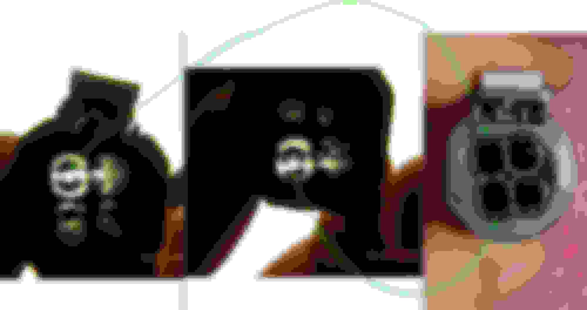
Unfortunately, this also sometimes caused the plastic “latch” mechanism to come loose from the connector
There are two separate plastic pieces inside the connector to latch it, an outer (top) gray one and an inner (lower) black one
I didn’t realize there were two plastic latch pieces so I dropped one of black (lower) ones into the abyss.
On two other coils the plastic latch pieces came out, and I thought I put them back in correctly, but they don’t latch well :-(
I’m ordering three of these connectors (p/n 0005458912) and will either take the plastic latch pieces out and transfer to the existing connector, or re-pin the new connectors to the harness.
So, if you are attempting this and wondering why the connectors are so blasted hard to remove, realize you are not alone :-)
Thanks for allowing me to vent
.
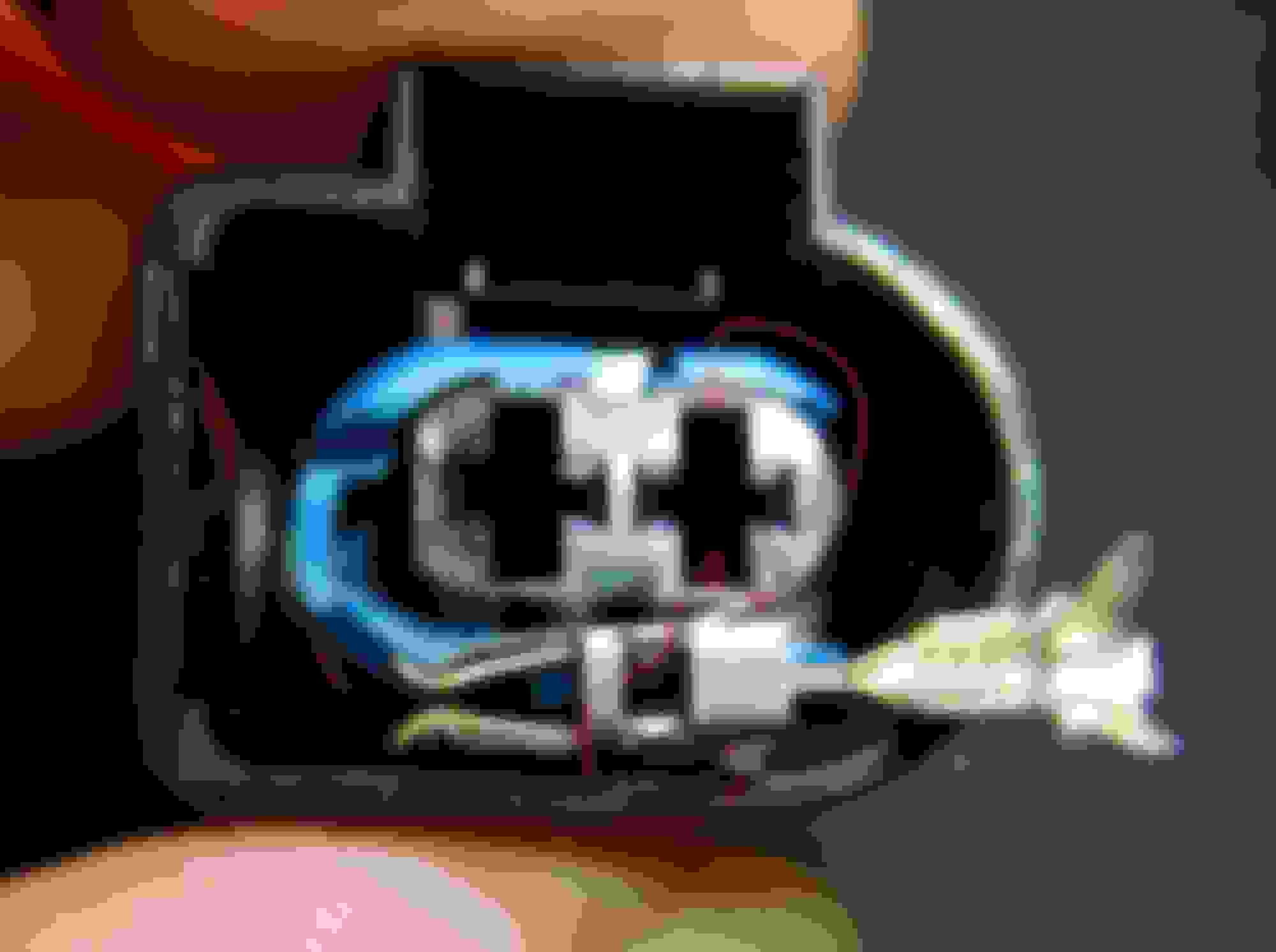
If you can just slide this connector off the coil, then more power to you. I needed a hammer ;-) Notice that the "latch" has two separate plastic pieces (gray and black) Yup, the black one slid out because I didn't know about the black piece underneath the gray ... which then fell into the great abyss
Last edited by ghlkal; 08-11-2021 at 04:59 PM.
Reason: updated "resolution"
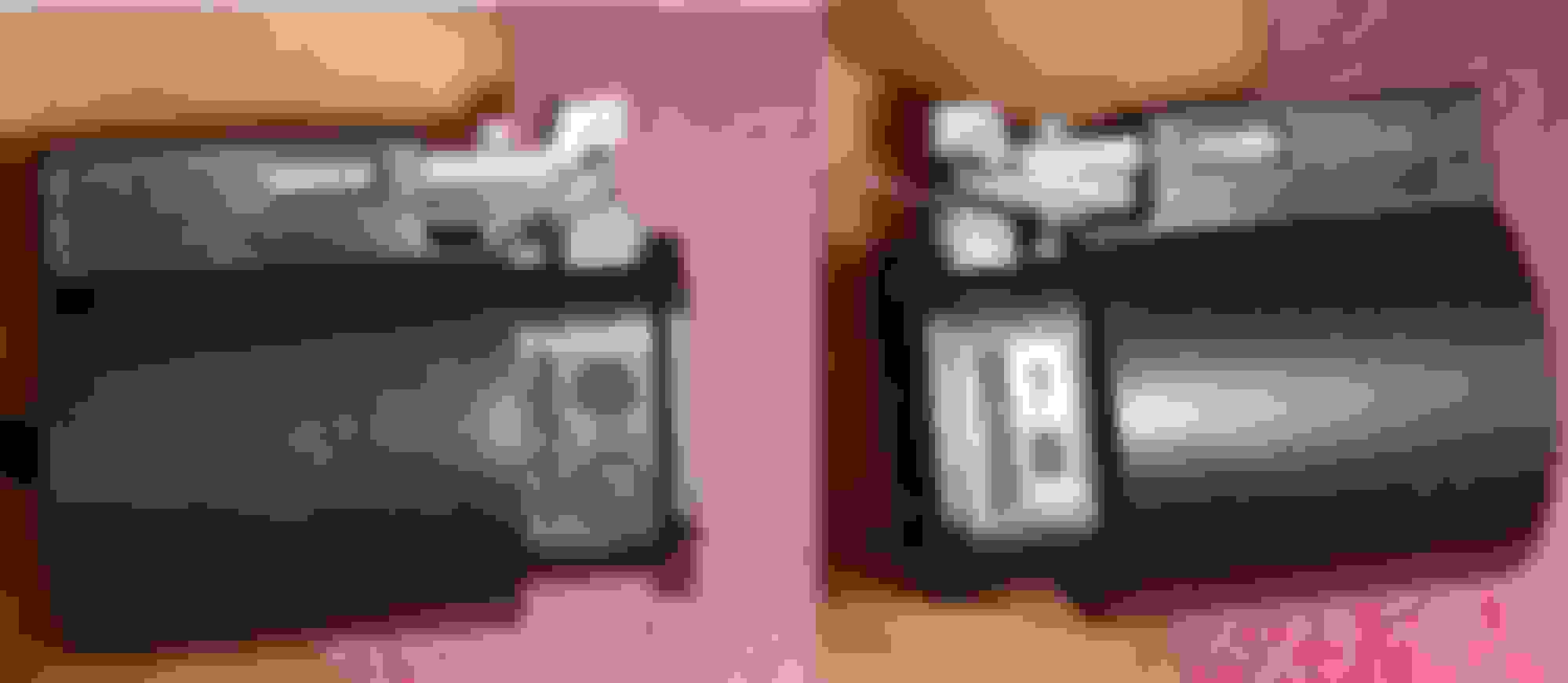
The latch lock mechanism works well as described by MB and easily removed , IF and WHEN, its inner black color locking lever mechanism has not been "frozen".
Only then, when black color locking lever is no more frozen..........pressing the grey/white top clip will push down the rear end of the black locking lever.
You see these plastic are easily bent with pressure, so the black locking lever can bend down when pressed at its rear hoping its front end to raise up, but its front end where the latching/teeth MAY NOT yet raised up to free itself from the notch...aka "frozen"
See my post on how to release the black locking lever for those "virgin" connector never been opened for a long time or never been opened since day 1.
Image 3 and 4
See my post on how to release the black locking lever for those "virgin" connector never been opened for a long time or never been opened since day 1.
Image 3 and 4
One more tip, and I just realized by visualization why some connectors are so stubborn and difficult to remove and when already removed, next few times it is much easier to remove.
These connectors have silicone rubber seal which produce sort of "tension and/or friction".
So...when you want to push down the white/grey locking top pin to also push down the black locking lever rear end ( the unseen lever inside ),FIRST push the connector INTO the sensor/coil and then you PUSH down the white/grey locking top pin.
You see , it is by nature that our fingers will tend to pull out the connector while pushing down the white/grey locking top pin.
The more we pull out the connector before the black lever ( the unseen lever inside ) can unlatch its teeth from the notch at sensor/coil, the more friction we create for that black lever. When we PUSH in the connector, we release the tension from the black lever teeth to notch of sensor/coil and then pushing down the white/grey locking top pin down will be more productive as the black lever inside more more freely.
The silicone rubber seal if still good and firm, its outward tension create friction for us when PUSHING the connector INTO sensor/coil.
You may actually can get away not using the toothpick , try it.
When I remove any engine connectors (coil, cam position sensors, cam magnets, air flow sensor, etc., I wipe the thinnest film possible of dielectric grease on all sliding surfaces. The engine connectors have a plastic female sheath on one end that slides over a mating male body on the other end. The sheath and body have a close tolerance fit, and dust gets in there, causing friction and difficulty in removal.
The thin film of dielectric grease on the connector halves is a similar approach used to grease the porcelain body of the spark plug when removing the ignition coils for spark plug replacement. The grease is not for better electrical contact, it's to avoid the ignition coil boot adhering itself to the porcelain body due to age and heat.
So, maybe the problem wasn’t the connectors were stuck on and needed to be hammered out. I just wasn’t getting the connector unlatched all the way.
I purchased some new connectors (p/n 000 545 89 12) to experiment with and replace the ones I screwed up.
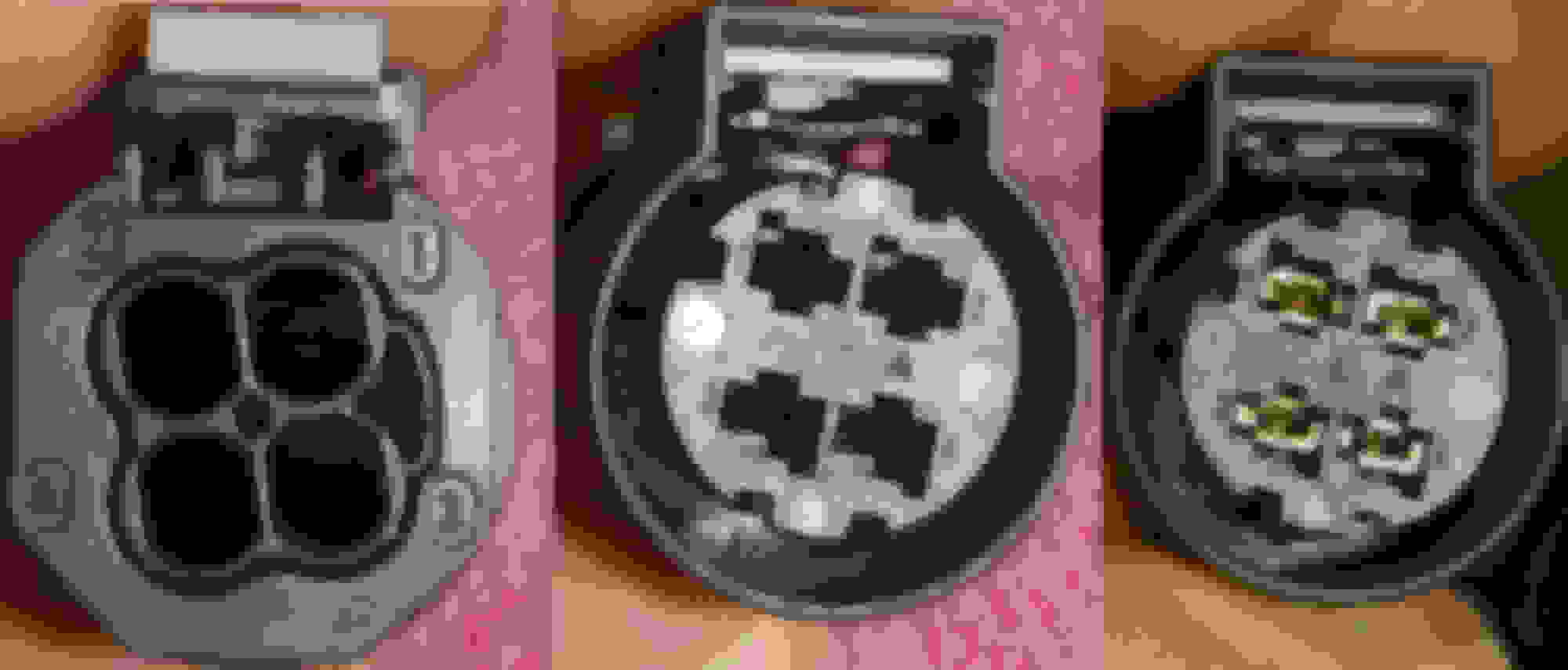
When I slid the new connector on my spare coil, I couldn’t remove it by unlocking the gray clip and pushing down! I could unlock it if I pushed down on the black piece underneath the gray clip.
I didn’t need to use a screwdriver – that’s just there to separate the two pieces for the pic. If I reached underneath the gray clip with my fingernail and pushed down on the black piece, I could unlatch and remove the connector.
It seems that the gray clip can’t quite push the black piece down enough to release. The black piece acts as a lever, where pushing on the one side will raise the other side and then release the connector from the coil housing.
On every other connector (cam sensors, etc), pushing the gray clip will unlatch the connector after it has been unlocked. So, I have no idea why this isn’t working on the coil connectors.
Hammering off the connector worked by forcing it over the locking tab, but this also broke off some of the black clips. While the gray lock clip can be removed (there are some “pegs” that hold it into the top on the side), it probably shouldn’t be removed. As far as I can tell, the black clip is part of the connector and doesn’t/shouldn’t come out. So now, I need to re-pin a few connectors to fix my mistake.
synopsis
To release the coil electrical connector, you need to unlock the gray clip (pull out) and then reach underneath it with a fingernail and push the black clip down. Then slide the connector off the coil.
Maybe this will help someone else. It will also remind me when I do this job again in 10 years
I had broken the connector and need to replace. i have the new connectors but am struggling with getting the wires to release on the connector . how where you able to release the wires from the connector. i have terminal removal tools
There are so many connectors on this car, and they all seem well made. But WHY do they all seem to have a different connect/removal technique. For example, my recently removed/reinstalled climate panel has three connectors - each with different latch mechanisms.
There are so many connectors on this car, and they all seem well made. But WHY do they all seem to have a different connect/removal technique. For example, my recently removed/reinstalled climate panel has three connectors - each with different latch mechanisms.
Why does Apple use lighting connector for their phones and most everyone else USB-C... just is.
I broke one of these gray clips, is it a big deal, or the black latch is enough? This one was on my ignition coil.
I must say I cannot believe one would use such stupid lock design - you pull one clip, then reach under it..., what purpose such design really serve??
The gray part is supposed to lock the black latch in place. I would think the black latch is enough, but what do I know? I couldn't get the freaking connectors off
Does anybody know how important these grey locking clips are to the integrity of the connection? We changed the plugs & coils, and broke a couple of those grey clips, and now the car has an even worse miss, and it has a spark detonation (loud high pitched burp) and is throwing code P0505 (IACV/AAV idle air control valve malfunction).
The ignition coil connector is not a friendly one to replace. I believe it is made by Kostal, I am out of town and can't access my database at home PC.
I have spare connector and its female terminals but never use/assemble it yet. I buy to make a test cable.
As I recall, it is not the easy to remove for its female connector unlike if a Hirschmann brand.
In a few days I will be back home. I will give many photos and information on how you guys can replace it up to the female terminal which is 2.8mm JPT ( Junior Power Timer ), correction : terminal is SLK 2.8mm yep a unique name indeed. Unique shape too.
This connector and its female terminal has one of the highest work load in our engine. That is why the female terminals is the robust 2.8mm JPT and the connector chosen
is that Kostal custom order by MB, almost can never get the connector on open market. Must buy from MB, its not crazy price , I think no more than US$25 each from MB Indonesia
and if from MB USA probably under US$15 each.
10-14 amps is the power pulse carried by 2 of the JPT female connectors along with vibration heat and whatnot.
The 2.8mm JPT female connector as with all connectors is good to probably 40-50 remove/install life cycle assuming MB uses silver coated one Mating Cycles:
10 (tin plated)
50 (silver plated)
100 (gold plated)
One more thing.......
Albeit MB uses good 2.8mm wide female terminal at the ignition coils, the one at the Engine Computer is MLK 1.2mm wide female terminal.
When I was troubleshooting my friends M271 ( also using 2.8mm wide female connector at the coil ), the poor contact which caused misfire code came from the engine computer side
which was using MLK 1.2mm ones, however this is oldie 2 wire dumb ignition where the MLK 1.2mm from engine computer carry the same 10+ amps of load like the 2.8mm at the coil.
2 wire coil power switching is from engine computer.
Your M278 is a 4 wire coil, so the MLK 1.2mm connector at engine computer is a very low current SIGNAL trigger only and the high power 10+ amps is direct to front SAM fuse/s.
4 wire coil does its power switching at the ignition coil and not at the engine computer.
I am just trying to point out, your issues can be bad contact from power terminals (2 terminals ) or from the trigger signal (1 terminal) too as something to keep in mind.
If you or your friend have a scope, you can see all 8 coils power consumption and trigger duration to further verify the culprit in detail.
If the scope has the Coil On Plug signal probe accessories, even better.
Misfire can be caused by many things and if you coils are not genuine, it can even leak out EMI and cause other DTC simply from the "noise".
My apology. The COP connector ( by Kostal ) is not using the JPT female terminal, the High Pressure Pump is the one using JPT.
COP uses SLK 2.8mm.
Attached the PDF of the connector.
I broke the black tab on the original coil connector and plan on swapping with a new connector. Outside of buying some really expensive terminal tool, does anybody have an idea on what I can use to release those slk2.8mm connectors?
Thanks that is very helpful! I think I was under the impression that there was only one release point (tongue) but from the pics in your reply it looks like there's one on each side.
If seeing the connector body (plastic ) the catch for the tounge seems only 1, but we never know the actual inner design which I can't see by its shadow alone
I could not release those terminals using the cheapo tools from Amazon. I'll try again tomorrow but if I'm unsuccessful, what are the chance that the connector can vibrate off without that black piece of the connector that functions as a locking mechanism?
Well that grey lock is a seconday lock to the 1st black latch/lock.
Grey prevent black from being able to lift up and release the connector from COP.
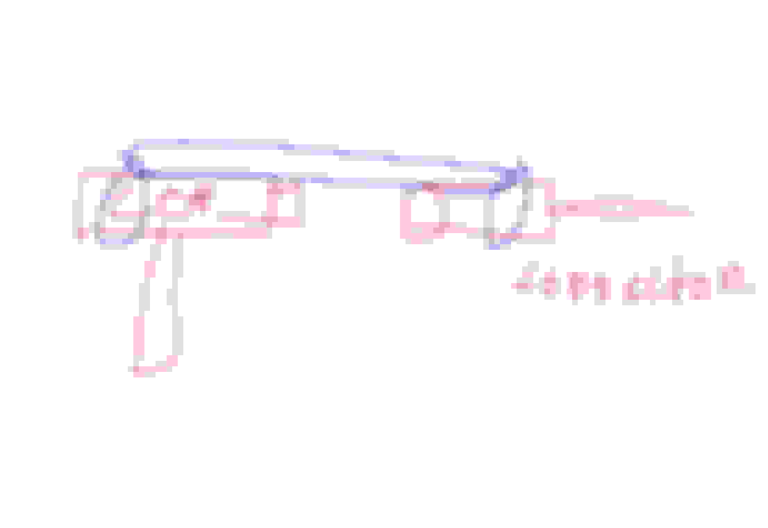
Use cable tie, 3 pcs. Make 1 loop at COP and make 1 loop at connector.
These 2 cable tie is then looped by a third cable ttie. So movement not possible.
very ugly drawing...sorry
I use this method often as added security for some application.

 07-29-2021, 08:53 PM


 , try it.


 ... I'll post my updated findings shortly