When you click on links to various merchants on this site and make a purchase, this can result in this site earning a commission. Affiliate programs and affiliations include, but are not limited to, the eBay Partner Network.
When scoping the laptop is not connected to the 220V power supply, safer and less noise.
I also do not use battery maintainer when engine running and while scoping.
Hp laptop for Picoscope use
Asus for Xentry use. Also no 220V power supply connected when used at the same time with HP + Pico...
Noise is a guaranteed to be picked up when near ignition sources, hence I try to raise the scope leads higher and also to prevent dangling scope leads chewed up by the fan
Well, the W10 is "cleaner" ground when engine is running and it is still the most upstream when you look at the battery.
I know what you mean by alternator with higher voltage when engine is running would be sort of more upstream.
Alternator is not a stable power provider, it is an amperage swinger.... unlike battery with massive energy buffer stored chemically and it smooth out alternator.
Whenever there is enough load on a circuit, its ground can never be flat when seen using a 12 bit scope. It can not be the true 0 Volt ground anymore if you scale the scope to very low voltage.
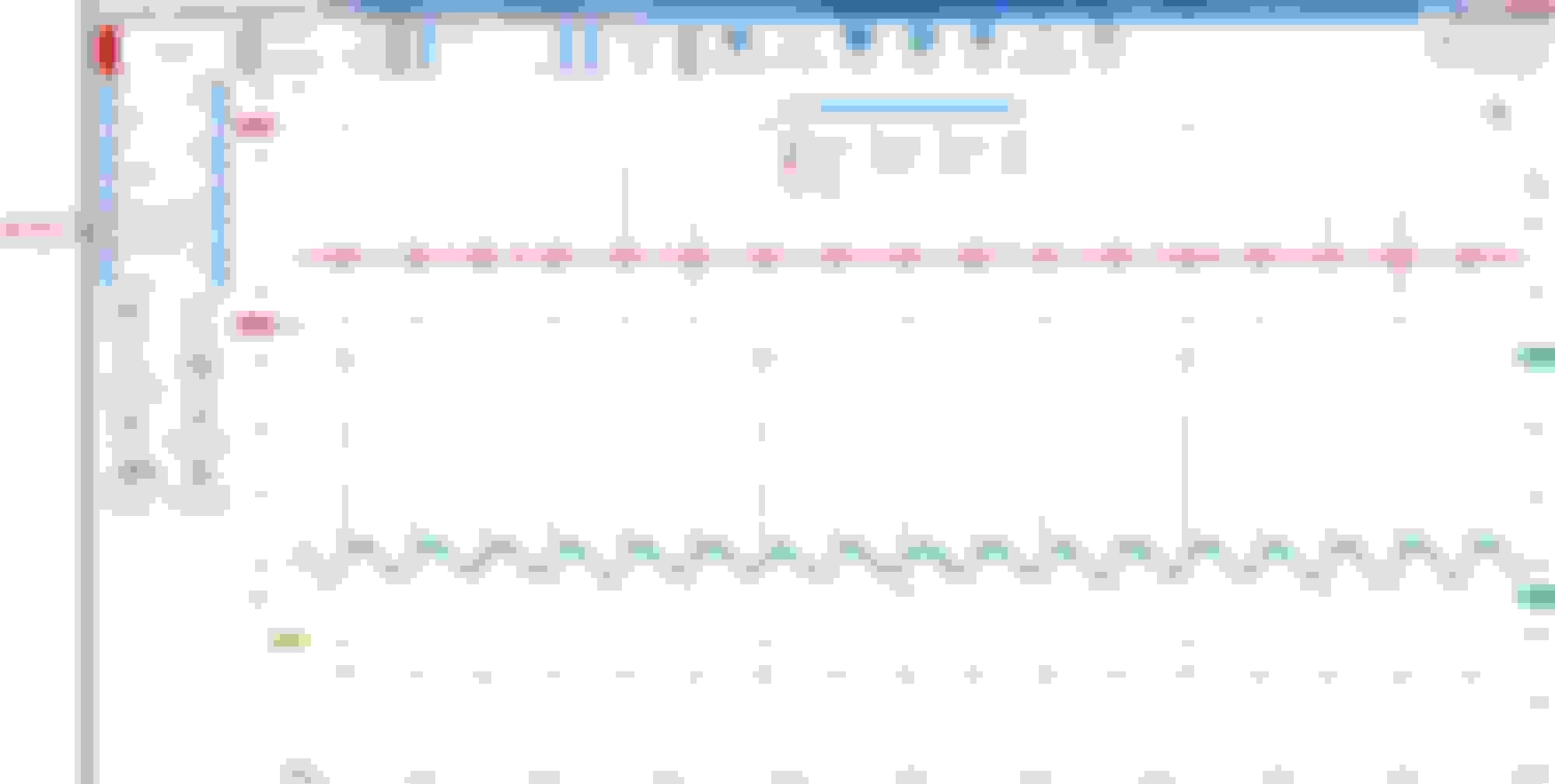
Here is pin 1 W16/5 and pin 2 W11 both at 10 volts scale.
Pin 2 , W11 green channel-C looks flat in reference to voltage at W10 stud. All 4 channels are using W10 as its ground.
At 100 millivolts scale, green channel-C Pin 2 W11 average activity will surprise us at -19 millivolts and the spike of +51 millivolts whenever this cylinder #4 fires. as seen by orange channel D, the 5V trigger signal from ECM to COP pin 4.
Albeit W10, W16/5 and W11 are all interconnected, loads on them are not the same.
Imagine W10 as main power feed to a small apartment tower and the W11 and W61/5 and all other W-s are a few apartments getting power from W10.
Since DMM or a scope is a differential measuring device, W10 as point A and W11 as point B1, Pin 2 of COP is like point B2 very close distance wise but not the same when under load.
Even if I measure between W10 near battery stud to W16/5, I will be able to read the differences at some low millivolts level.
=====
Now let me zoom Pin 1 W16/5 signal to ECM, the Ground Signal of the COP firing confirmation.
Zone A is when ECM sent the 5 volts to the trigger circuit to allow the MOSFET or whatever the name of the transistor switch used to saturate the primary coil of COP. Channel D orange. This is the dwell time.
Since COP only works producing spark when power is removed, zone B represent the duration of 36/1,000,000 of a second or 36micro-second the 5V trigger power has gone and at the
same time is the primary winding's delay before releasing its energy as Zone C, the spark event.
Zone C as the peak of spark event.
My interest is Zone D, red B-channel which is Pin 1 W16/5 , see the time difference between zone C and D.
Whatever method MB engineers choose as firing confirmation we are seeing it as 2.4 volts signal of 10 microsecond peak ( 28.8 micro-second of peak and valleys ) from Pin1 to w16/5,
right after COP coil pumped out its peak energy release.
Different to W11 Ground for Power, which does not exceed +60 millivolts spike ( Zone A ) and that spike was like 1000 microsecond earlier than zone D and its duration is equal to
voltage drop duration at pin 3 fuse 24 +12V. of approx 850 microseconds.
To the ECM this kind of signal from W16/5 is "slow" easy one I am sure.
NOTE : if I use 4 Million Sample per second, I will have better horizontal resolution but my total capture will be only 32 pages or 16 seconds max.
I am not a microsecond guy, millisecond is as fast as I am usually familiar with and still can relate.
You should get this 4425A Picoscope Cali, its worth every penny, more so because you have a better understanding of digital data transmission and IT stuff..... way better than me.
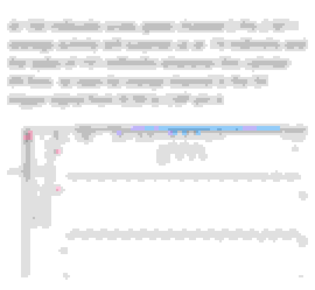
Good news, some of the odd display is actually insignificant upscaled 50mV noise.
An oscilloscope provides us with an ultra clean input amplifier to look at various signals: small or big voltage fast or slow frequency.
Here: tiny noise shown in mV scale
SNR: signal noise ratio:
A 50mV noise can be overlooked because 0.05V is not significant compared to a 12V signal, true?
We have a big signal and small noise: all right that's what we always want.
3 types of noises clearly mixed together: We see spikes in phase with ignition activities
We see AC sinewave (like a 50/60Hz)
We see harmonics modulating AC noise
What to make of that noisy GND:
When you make a measure and the result you get is unexpected, it's up to you to question what you are doing.
Eg: if you measure a significant voltage in GND, its either a bad measure or a bad GND.
Here you can bet there's a open circuit because there are so many oscillations mixed together... this input looks very much like an open wire antenna signal picking up noise off the air.
That's really unlike a flat reference GND.
We can ask ourselves is it truly the circuit looking like that or is it something we are doing to the circuit that makes it look odd?
Scoping GND basically offer us a "flat pancake expectations". Let's get to that.
> Coil "Feedback" EMF :
All electrical coils generate feedback EMF, this is true for Ignition COP, Audio Speakers, Relays, door bells, transformers. This "coil feedback" is simply the energy discharge out of the magnetic core once power is interrupted.
That's where in DC circuits, a reversed diode is used to protect controls from destructive reverse voltage originated in the coil induction.
Eg: Every electro-mechanical relay On/Off cycle creates a spike followed by its harmonics.
Eg:This EMF is what burns a motor contactors with a spark when contacts opens!
Section D after Spike C... classic
the characteristic ringing of harmonics
Above is the caracteristic harmonic oscillations that are generated by switching any inductor back to zero. This happens in every inductive circuits.
it's good to consider this EMF NOISE to minimize it with a lower impedence wiring ie. upsize 12V feed conductor to lower R.
The oscillations frequency of this circuit is based on RxL values.
Practically ignition requires a large Inductor to work, so the only value we can play with is lower R wiring equivalent.
Wiresneed to be short and sized right to conduct the spike with minimal loses.
Dealing with frequency and power applications requires to consider :
Current Max values
unwanted electrical noise
undersized resistive conductor
crasstalk between parallel lines
AC circuits are very similar to DC circuits with a twist caused by the base frequency plus harmonics.
That's not exactly new, right?
++++++ ringing oscillations standard harmonic oscillating circuits
This shows the characteristic harmonics with increasing frequencies and decresing amplitude.
++++++ measuring circuits:
When troubleshooting we use tools to gain physical insight on what's practically happening.
We can make sense of a result from DVM or scope because we have expectations from the circuit under test.
We can Pass/Fail a test based on the expectation we have. When results/expectations are mismatched we investigate
Last edited by CaliBenzDriver; 06-21-2023 at 02:21 PM.
Well, MB is crazy enough to use "noise" as confirmation of firing , unlike dedicated IGF wire to ECM like Toyota firing confirmation on their 4 wire COP.... I guess
cleanliness and tightness of all Ws ground points is even more important than ever.
BTW, how did you clean your W16/5 eyelet and the body stud Cali ? You pointed out its hidden near the brake booster.

 06-20-2023, 12:04 PM