When you click on links to various merchants on this site and make a purchase, this can result in this site earning a commission. Affiliate programs and affiliations include, but are not limited to, the eBay Partner Network.
And then I think back, dang I seen that HILL AND VALLEY for ALTERNATOR CURRENT pattern too on my alternator when using PicoScope and could never explained why I am seeing that ,
other than I assumed it is the load which caused that and not alternator own design limitation.
.
Placement of Current Clamp in purple, ALTERNATOR and BATTERY
I was actually scoping COP and not alternator per se.
.....
Channel C - Green is current clamp at Fuse 24, which powers all COP 1, 2 and 3 at BANK 1. Bank 2 uses its own fuse for their COPs.
Channel D - Brown is current clamp pin 3 of COP, which is COP's +12V power input.
.
Now I realized something I have known but never really pay attention to. It is the 3 phase 50hz 230/400V generator I been dealing with.
Our alternator is a 3 phase AC alternator, retrified to non pure DC using 6 diodes , as shown in video below :
Nothing is a DC as a battery in terms of pure DC. Basically a flat line with no hills and valley.
Unlike retrified DC from alterator, since the way AC 3 phase power is produced is ALTERNATING aka hill and valley, and we chop chop part of it to make a flat DC,
we can not have a truly flat DC output.
I did not expect in engineering speak by alternator manufacturer that the swinging hill and valley of current output is called CURRENT RIPPLE.
I would call it UNSTABLE current hahahahah.
Take a closer look at how our main battery is also acting as a power provider providing amperage when needed during the valley or deficit current by the alternator.
When you see below as BATTERY current, this is the same amperage your B95 battery sensor is looking at, but it will surely show about 10+ amps only and not the negative/deficit as it will average the values.
B95 sensor and the current clamp I placed at the same cable, is totally only monitor what battery is getting as surplus or deficit, nothing to do with other electrical consumers of the car. Simpy it is a NET value.
This 1 page scope capture is worth 500 millisecond if full page, I am showing below at approx 150 milliseconds ( 50 ms/division ) or 3 divisions.
So in every 1 second , the battery will provide approx 30% of the time or 300 milliseconds of the alternator deficit amperage, because by nature the alternator itself have that CURRENT RIPPLE.
CURRENT RIPPLE is not the same as what usually we call AC Ripple of an alternator...which is for VOLTAGE.
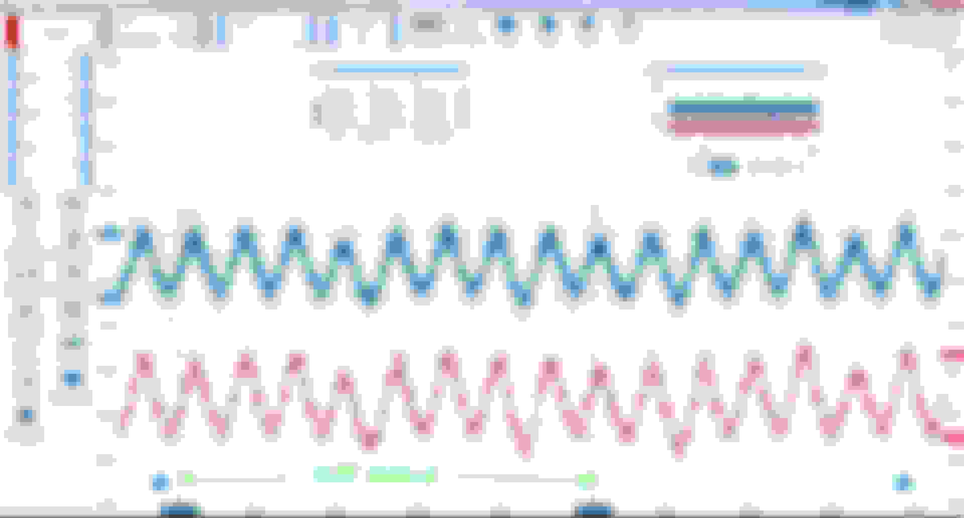
Below is AC ripple of an alternator VOLTAGE, not current.
Channel A, blue trace - At alternator POSITIVE stud/lug, its AC ripple is higher at 191 millivolt, 0.19 volt AC peak to peak.
Channel B, red trace - At F32 copper bar ( where you charge your battery +positive ), it get smoothing out by the battery, which is still 30cm away by a 50mm wire. Hence only 148 millivolt or 0.15 volt AC peak to peak ripple.
If I read at battery positive post directly and not af F32 copper bar, I will get even lower AC ripple for channel B red trace.
Seeing on a scope with 2 million data point per second is scary because we can see such details, unlike a DMM.
============
This information will answer most questions as to why when our main battery is not healthy, the car electronics can go banana ..... where we assume we have alternator providing all the DC
power and it should be OK.... hhhmmmm.
SUMMARY :
01. Good healthy battery will smooth out better the AC Ripple Voltage of alternator. High AC VOLTAGE ripple can cause havoc to CAN BUS or to Crankshaft position sensor of the AC waveform type.
02. Good healthy battery covers the amperage deficit of alternator cause by the CURRENT RIPPLE , albeit it is only very short duration within per every 1 second.
I suppose you could call it unstable, but it's doing exactly what it's supposed to be doing so ripple is a better descriptor.
That ripple is a non-issue, and it can be massive and still work just fine. The max ripple in that doc is just a way to note if the Alt is working right or not. Kinda like an engine compression test. You could completely lose a phase and it still works, maybe even two phases and ripple would be at 100%, but the remaining phase(s) has to do the work and it may not like it. If two phases died, the remaining phase diodes would likely give up the ghost, but it all depends on the Alt size, draw, Diodes and cooling it has. If you kept the Alt cool it would probably run on one phase until the bearings give out.
It's interesting stuff to learn. If you want to geek out some more, and I know you do, check out reactive power, or VAR. It's happening in your car too, but like ripple, you car/Alt doesn't care at all.
There's a book I suggest people read, if interested in electronics/electricity: https://n5dux.com/ham/files/pdf/Forr...lectronics.pdf
It's really good at explaining, unlike typical school books. Once you really understand electricity, everything about it makes sense. AC power, Transistors, everything Well, almost. Eg; nobody knows wth Ball Lightning is.
Ripples are to electricals what oil leaks are to engines.
This is a very interesting topic from now and on. Our future cars are all based on 3-Phases.
3-Ph circuits are the best way to split power over 3 cables and minimize ripples over the 360� the AC sinusoidal works. Each rectified phase helps cover weaknesses of the 2 others.
The best way to minimize ripples is to have a fully charged battery with low internal resistive value. The battery acts as a capacitor.
Each individual modules are built with capacitors to smooth the ripple noise.
Special capacitors technology called "low ESR" provide power to smooth current ripples such as made by in-tank fuel pump. This is used in DC-DC power converters that run at higher frequencies.
> Decreasing ripples:
Ripples are not only from ALT. They are created by everything that has poor connection.
The enemy of ripples is low resistance + low current. That makes low drop voltage ie. low ripples.
Good WTF GND strap return to help battery
Good nearby GND to help power module
Healthy battery conditions (CTEK)
Low current load
Regulated Voltage in DC Load.
> Ripples as modules killers:
Poor ripple control results in premature failure.
When the low ESR caps are aged, the modules begin to be affected by higher noise level.
I suppose you could call it unstable, but it's doing exactly what it's supposed to be doing so ripple is a better descriptor.
That ripple is a non-issue, and it can be massive and still work just fine. The max ripple in that doc is just a way to note if the Alt is working right or not. Kinda like an engine compression test. You could completely lose a phase and it still works, maybe even two phases and ripple would be at 100%, but the remaining phase(s) has to do the work and it may not like it. If two phases died, the remaining phase diodes would likely give up the ghost, but it all depends on the Alt size, draw, Diodes and cooling it has. If you kept the Alt cool it would probably run on one phase until the bearings give out.
It's interesting stuff to learn. If you want to geek out some more, and I know you do, check out reactive power, or VAR. It's happening in your car too, but like ripple, you car/Alt doesn't care at all.
There's a book I suggest people read, if interested in electronics/electricity: https://n5dux.com/ham/files/pdf/Forr...lectronics.pdf
It's really good at explaining, unlike typical school books. Once you really understand electricity, everything about it makes sense. AC power, Transistors, everything Well, almost. Eg; nobody knows wth Ball Lightning is.
Yes I am familiar with power factor of 3 phase AC system.
Its just so unique in a car DC alternator where it has no fixed frequency per se unlike our AC voltage system, where if in my 50hz land, a medium size 3 phase 230/400V generator
say 500 - 1,000Kva will be at 1,500RPM for 50Hz and for your 60Hz market the same generator will be at 1,800 RPM.
At idling of 600RPM crankshaft, if based on a 12 pole alternator with pulley ratio 2.xx , it will be like approx 150hz frequency for the alternator AC side.
Ripples are to electricals what oil leaks are to engines.
This is a very interesting topic from now and on. Our future cars are all based on 3-Phases.
3-Ph circuits are the best way to split power over 3 cables and minimize ripples over the 360� the AC sinusoidal works. Each rectified phase helps cover weaknesses of the 2 others.
The best way to minimize ripples is to have a fully charged battery with low internal resistive value. The battery acts as a capacitor.
Each individual modules are built with capacitors to smooth the ripple noise.
Special capacitors technology called "low ESR" provide power to smooth current ripples such as made by in-tank fuel pump. This is used in DC-DC power converters that run at higher frequencies.
> Decreasing ripples:
Ripples are not only from ALT. They are created by everything that has poor connection.
The enemy of ripples is low resistance + low current. That makes low drop voltage ie. low ripples.
Good WTF GND strap return to help battery
Good nearby GND to help power module
Healthy battery conditions (CTEK)
Low current load
Regulated Voltage in DC Load.
> Ripples as modules killers:
Poor ripple control results in premature failure.
When the low ESR caps are aged, the modules begin to be affected by higher noise level.
Mercedes SLR McLaren 722 S Is Extremely Rare Example Modified by McLaren
Slideshow: A one-of-one U.S.-spec Mercedes-Benz SLR McLaren Roadster became even rarer after a factory-backed transformation at McLaren's headquarters.


 yes yes yes


 Well, almost. Eg; nobody knows wth Ball Lightning is.


