When you click on links to various merchants on this site and make a purchase, this can result in this site earning a commission. Affiliate programs and affiliations include, but are not limited to, the eBay Partner Network.
Wipers move up and down in small increments and then stop. Wipers do not go on.
2012 E350 Coupe
As the title states, wipers never make full travel across windshield and only moves up and down a 1/2" and does so three times and then stops.
I took the arms and cowling off and there's nothing loose and no obstruction. Unplugged the motor connector and replugged, there's no corosion. Checked fuses 10 & 13 and they're okay. I can make the arms travel full length by hand.
Relay K provides power as 15R
15R is the power source of Fuse 10 ( F10) which is for Wiper Motor M6/1 , Positive feed.
There inside the front SAM, the wiper control is using driver circuit, the one with transistor icon/label.
The negative is taken direct from Front SAM internal and not stand alone ground wire, #31 is always negative.
That negative final source is the ground stud 15/5 with 4mm brown wire ....if for Left Hand Drive car, example USA.
U12 is LHD car, U13 is RHD car.
.
.
Relay K ( the 15R power line positive ) serves not only wiper motor, it also serves Wiper Park Heater which is embedded inside the front windshield and
it also serve other devices. Fuse 9 for my car is not in use.
---------------------
What you need to do is back probe the 3 way connector to the wiper, to see massive voltage drop if it does exist.
Pin 2 brown wire 2.5mm is the negative and Pin 1 Red-Green 2.5mm is the positive.
Lock the 2 latch of hood, it has 2 switches where when hood is un-lock, the wiper wont be allow to run.
Test wiper and see voltage drop. Anything below 11V when wiper is running.... is not good, this is assuming you have battery voltage at 12.7V minimum with a power supply ( battery maintainer) attached to battery
or do the math, where 2V voltage drop is already bad when and if you do not have battery maintainer
This is a Right Hand Drive car wiper connector, its wire to pin arrangement is different than LHD car.
However pin number is the same, as the connector is the same.
As per schematic, LHD car uses Pin 1, 2 and 4. RHD car uses Pin 1, 4 and 3.
U12 is LHD car, U13 is RHD car.
The said ground post W15/5 will have total 3 wires, because other devices is also using it.
1 of 0.5mm brown wire and 2 of 4mm brown wires. See below :
.
First 4mm brown wire
.
Second 4mm brown wire
.
Location of W15/5 as per WIS, based on LHD car is attached.
Its LHD car driver side foot well, inside the car.
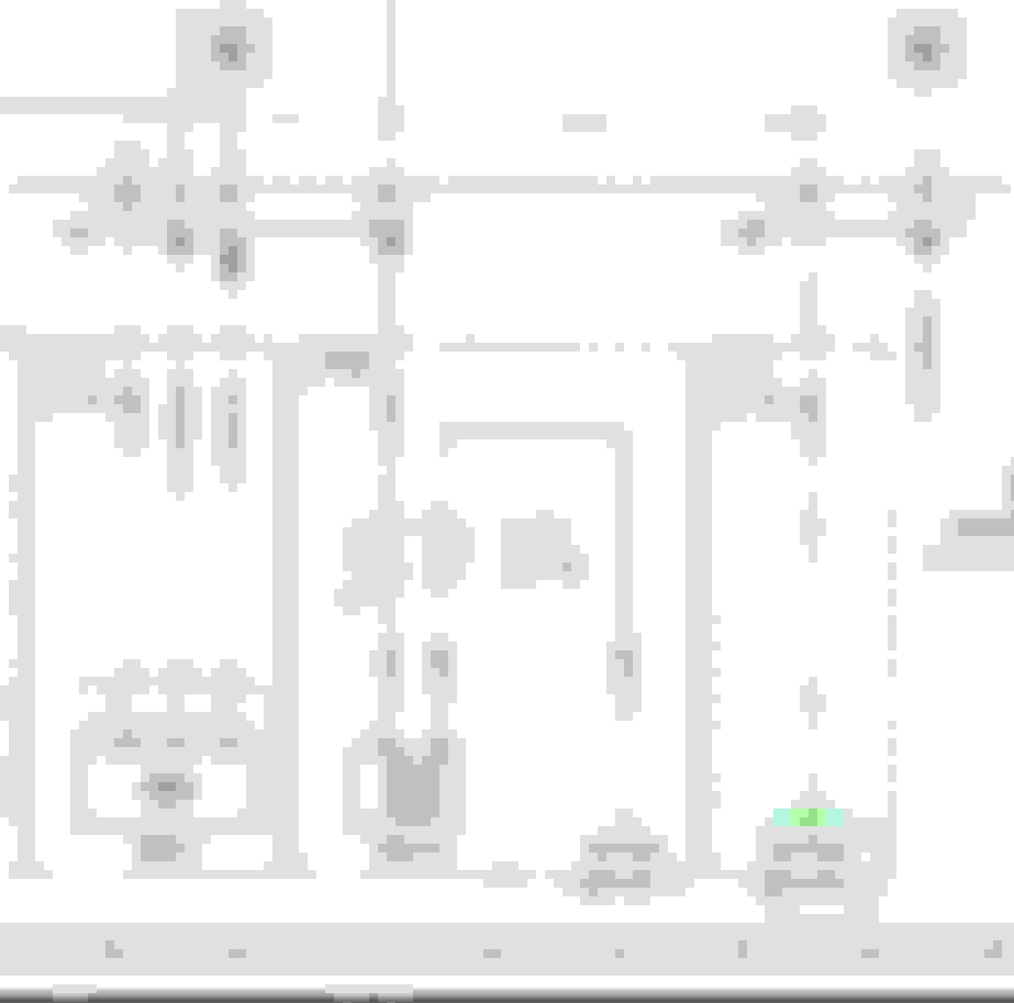
Front SAM sheet 1 wiring diagram for wiper also attached.
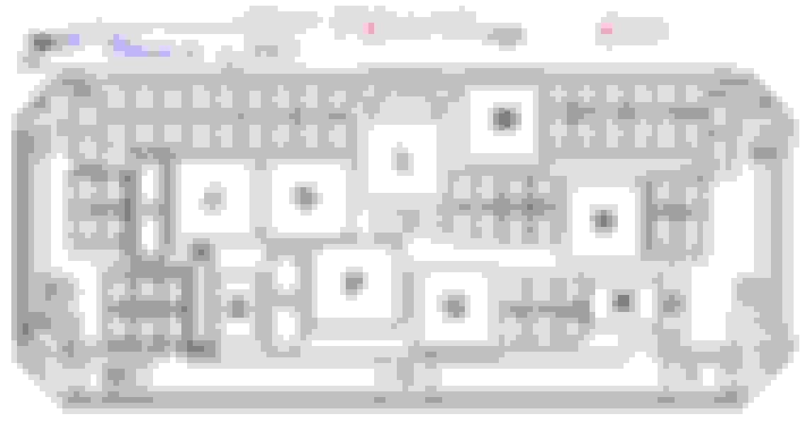
Relay and fuse layout at front SAM is below :
If you want to lighten the wiper motor load, you can remove both wipers and run it wiperless.
I hope there is no damage in the gearing inside that wiper motor and only bad electrical contact .
I hope you do not need to go into the SAM connectors, but you are in luck........
If you do, this is the connector 1M for wiper at front SAM top part and not bottom.
This is connector position, only 1M is on top, lucky you.
Good luck troubleshooting...........
Last edited by S-Prihadi; Sep 22, 2024 at 11:19 AM.
Relay K provides power as 15R
15R is the power source of Fuse 10 ( F10) which is for Wiper Motor M6/1 , Positive feed.
There inside the front SAM, the wiper control is using driver circuit, the one with transistor icon/label.
The negative is taken direct from Front SAM internal and not stand alone ground wire, #31 is always negative.
That negative final source is the ground stud 15/5 with 4mm brown wire ....if for Left Hand Drive car, example USA.
U12 is LHD car, U13 is RHD car.
.
.
Relay K ( the 15R power line positive ) serves not only wiper motor, it also serves Wiper Park Heater which is embedded inside the front windshield and
it also serve other devices. Fuse 9 for my car is not in use.
---------------------
What you need to do is back probe the 3 way connector to the wiper, to see massive voltage drop if it does exist.
Pin 2 brown wire 2.5mm is the negative and Pin 1 Red-Green 2.5mm is the positive.
Lock the 2 latch of hood, it has 2 switches where when hood is un-lock, the wiper wont be allow to run.
Test wiper and see voltage drop. Anything below 11V when wiper is running.... is not good, this is assuming you have battery voltage at 12.7V minimum with a power supply ( battery maintainer) attached to battery
or do the math, where 2V voltage drop is already bad when and if you do not have battery maintainer
This is a Right Hand Drive car wiper connector, its wire to pin arrangement is different than LHD car.
However pin number is the same, as the connector is the same.
As per schematic, LHD car uses Pin 1, 2 and 4. RHD car uses Pin 1, 4 and 3.
U12 is LHD car, U13 is RHD car.
The said ground post W15/5 will have total 3 wires, because other devices is also using it.
1 of 0.5mm brown wire and 2 of 4mm brown wires. See below :
.
First 4mm brown wire
.
Second 4mm brown wire
.
Location of W15/5 as per WIS, based on LHD car is attached.
Its LHD car driver side foot well, inside the car.
Front SAM sheet 1 wiring diagram for wiper also attached.
Relay and fuse layout at front SAM is below :
If you want to lighten the wiper motor load, you can remove both wipers and run it wiperless.
I hope there is no damage in the gearing inside that wiper motor and only bad electrical contact .
I hope you do not need to go into the SAM connectors, but you are in luck........
If you do, this is the connector 1M for wiper at front SAM top part and not bottom.
This is connector position, only 1M is on top, lucky you.
Good luck troubleshooting...........
What an amazing reply- just WOW! My deepest gratitude for such a detailed explanation.
The bit on the hood lock will probably save me a ton of time. Logical but who knew!
2016 E350 4Matic wagon, 2019 Ford Expedition, 2019 Chevy Bolt EV
Originally Posted by CaliBenzDriver
...
LIN:
Single line serial wiper control issue is not all that common to research.
LIN is a serial protocol, used in multiple places, think of it as a low speed CANbus. LIN is used to control the alternator voltage regulator, I think its used for the door modules to control the locks and windows, and various other low speed things like that, not just the wipers.
LIN is a serial protocol, used in multiple places, think of it as a low speed CANbus.
LIN is used to control the alternator voltage regulator, I think its used for the door modules to control the locks and windows, and various other low speed things like that, not just the wipers.
Yes, LIN remains in couple places. It's the old legacy economical single-wire slow version of the newer faster CAN differential pairs.
It operates in reference to common GND with limited noise immunity over short distance.
Commands a validated by multiple repeats.
I don't know exactly how the wiper internal module looks like ...
The wiper arms posts really need lube, the gearbox has the special light sticky stuff and the circuit board, who knows exactly??
2016 E350 4Matic wagon, 2019 Ford Expedition, 2019 Chevy Bolt EV
Actually, LIN is newer than CAN, it came about because implementing CAN was too expensive in the early 90s. and there's certainly places where a slower bus is plenty good enough.
CAN dates back to the mid/late 80s, although the first car to actually use ti was the W140 S class in 1991. originally, CAN supports 500kBit/sec and later versions go up to 20Mbit/sec. CAN is a shared peer to peer broadcast bus, where there can be 2000 or more nodes on a CAN bus, and each 'talker' broadcasts its messages on the shared bus, any number of other nodes can listen.
LIN was proposed circa 2000s and runs at speeds like 19kBit/sec. LIN is master/slave, with 1 master and up to 15 slaves on a given bus.
It seems this board is not a power board, probably position sensor board and something of that light duty.
The Front SAM is the one doing the power management/handling. Dang, it seems if the driver circuit for wiper motor went bad in Front SAM, we then need to replace the entire Front SAM.
1995-2002 GM wiper Pulse Board. Looks like this is also a Power Board.
2016 E350 4Matic wagon, 2019 Ford Expedition, 2019 Chevy Bolt EV
before replacing the front SAM, I would measure the outputs on the wiper motor leads, AND isolate those and feed power into the motors over the harness and verify the wipers move.
Actually, LIN is newer than CAN, it came about because implementing CAN was too expensive in the early 90s. and there's certainly places where a slower bus is plenty good enough.
CAN dates back to the mid/late 80s, although the first car to actually use ti was the W140 S class in 1991. originally, CAN supports 500kBit/sec and later versions go up to 20Mbit/sec. CAN is a shared peer to peer broadcast bus, where there can be 2000 or more nodes on a CAN bus, and each 'talker' broadcasts its messages on the shared bus, any number of other nodes can listen.
LIN was proposed circa 2000s and runs at speeds like 19kBit/sec. LIN is master/slave, with 1 master and up to 15 slaves on a given bus.
Do you know if the LIN supports bidirectional signaling for wipers to report position and SAM to manage power for intermittent, speed 1, speed 2 ??
My favorite LIN is the Hyundai battery module that snakes from the engine bay all the way to the trunk so Rear-SAM can report battery vitals over CAN back to Front-SAM then finally to ECU... instead of connected directly to ECU 2Ft away - The outcome is premium YoYo to overwork AGM batteries.
Last edited by CaliBenzDriver; Sep 23, 2024 at 12:37 PM.
It seems this board is not a power board, probably position sensor board and something of that light duty.
The Front SAM is the one doing the power management/handling. Dang, it seems if the driver circuit for wiper motor went bad in Front SAM, we then need to replace the entire Front SAM.
1995-2002 GM wiper Pulse Board. Looks like this is also a Power Board.
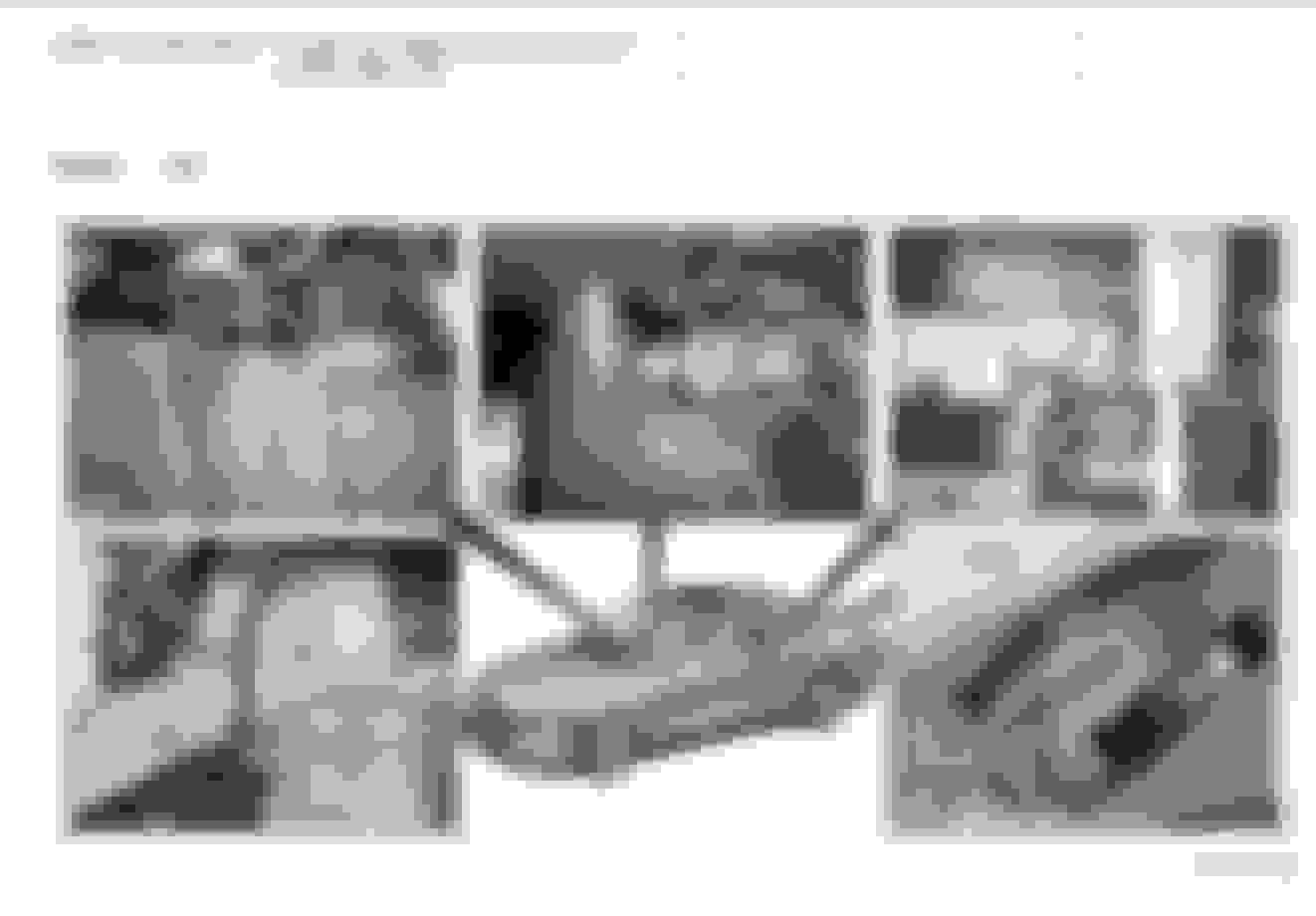
Thank you Surya for finding this remarquable piece of Bosch electronics.
With its SMD components it's more modern than the GM throuholes was.
wiper gear control module
1-- The first thing we spot is no solderless pins were used. That in part explains its favorable reliability.
2-- Next we see left over blue silicone spread over heavy GND throuholes drillings. I think that evidence of an economical MOSFET heatsink.
3-- We spot power coils to help stock local glitches from traveling back out to SAM.
4-- We're here to spot what can go wrong with this is clever German design...
We can expect current to be measured by a shunt and protected dynamically by the MOSFET, much like cabin fan module.
The wipers running short motion suggest the position sensing is acting up, not so much the motor power side.
Unfortunately we are limited by the PCB being soldered. We want to inspect the other side where gear position is picked up by a hall or optical sensor.
This is where decision will need to be made to desolder the board out or not!
5-- So before dismantling anything the 1st step is to do a good job troubleshooting with your scanner so you have confidence where problem lays: chassis side or wiper-gear internal ??
Overlooking the soaked hood sensors may cost you more than necessary. Don't rush to replacing anything... follow evidence to test conditions.
With these results, you can make educated guesses with better odds.
++++ CHEAP TIP ++++
When you RTV-Silicone all your harness connectors don't forget the tiny hood switches L+R.
Last edited by CaliBenzDriver; Sep 23, 2024 at 02:45 PM.
2016 E350 4Matic wagon, 2019 Ford Expedition, 2019 Chevy Bolt EV
Originally Posted by CaliBenzDriver
Do you know if the LIN supports bidirectional signaling for wipers to report position and SAM to manage power for intermittent, speed 1, speed 2 ??
My favorite LIN is the Hyundai battery module that snakes from the engine bay all the way to the trunk so Rear-SAM can report battery vitals over CAN back to Front-SAM then finally to ECU... instead of connected directly to ECU 2Ft away - The outcome is premium YoYo to overwork AGM batteries.
yes, LIN is bidirectional. The Master on a given LIN bus initiates all communications, it can send a command to a device or ask a device to report.
yes, LIN is bidirectional. The Master on a given LIN bus initiates all communications, it can send a command to a device or ask a device to report.
so the SAM could very well be remote controlling the wiper motion based on position sensors.
At least the local module is not solderless to be temperamental... relief
2016 E350 4Matic wagon, 2019 Ford Expedition, 2019 Chevy Bolt EV
looking at my 2019 wiring diagrams, the wiper motor itself has quite a bit of contol stuff inside including 3 relays and an electronic block. The LIN signal to it goes to the Window Patch Lane Departure Warning Heater and to the Steering Column Control Module/ SCCM also has a MS CAN interface. The Battery Junction Box has a relay that supplies power to the wiper motor
yikes, I was looking at my Ford Expedition wiring diagrams, hah hah. NEVER mind
Last edited by Left Coast Geek; Sep 23, 2024 at 03:50 PM.
you're seeing schematic with on-board piwer control for independent wiper management.
the big question how does Bosch control the wiper speeds... we can expect active electronic rather than dual copper windings.
Bosch keeps innovating with advanced solutions for established needs.
Last edited by CaliBenzDriver; Sep 23, 2024 at 03:35 PM.
I thought I would give everyone an update and to thank all those that contributed. After an exhaustive diagnostics, I found the culprit which was the wiper arms splines. Apparently the previous owner had taken them off at some point for whatever reason and did not replace them back properly and over time the splines wore out to the point that they never engaged. I bought a used set off ebay and installed them and the wipers now work perfectly. Incredibly frustrating experience but I learnt a few things along the way. Thank you for everyone's contributions.
Mercedes SLR McLaren 722 S Is Extremely Rare Example Modified by McLaren
Slideshow: A one-of-one U.S.-spec Mercedes-Benz SLR McLaren Roadster became even rarer after a factory-backed transformation at McLaren's headquarters.