Low cam sensor voltage left bank
#1
Junior Member
Thread Starter
Join Date: Aug 2013
Location: St Paul, Minnesota
Posts: 47
Likes: 0
Received 2 Likes
on
2 Posts
2002 ML320, 2000 eE430 4matic, 2009 ML350 4matic, 1986 Vanagon(subaru powered)
Low cam sensor voltage left bank
2009 ML 350 4matic Ran flawlessly. Start up and CEL light flashes, serious drivability issues, and returned immediately to garage. It has misfire codes for left bank, cylinders 4,5,6 and general misfire code. Additionally the cam sensor and cam solenoids on the left bank are shorted to ground or short circuit to positive or open circuit. The sensors do not receive 12 volt from the harness, while the right bank, both cam sensors receive 12 volt.
This vehicle is bone stock, the wire harness is untouched and does not look crimped etc. Hesitant to start ripping it open. On electric schematic, it looks like left bank power goes to the air intake sensor (B2/5b1) and then to the sensors. The vehicle had the extra wiring harness to to the cam solenoids installed. The solenoids have correct resistance.
The lack of proper voltage at cam sensors fits with the 0757 and 0765 errors. The 0070 and 0282 errors seem like they would go along with the cam sensor low voltage, maybe not. Ground continuity is good at sensor plugs. Is the misfire code providing overlooked information?
Battery has excess 12 volts, and starter is healthy and spins fast. Problem still exists when battery is boosted to 13 volts. Power to the sensors is through fuse 43 and relay 87 according to ALLDATA, the fuse in the rear panel (43) is good. However, when it is pulled, I read voltage at cam sensor connections. The good bank is still 12 volts and the bad bank is 2.5 volts. The importance of fuse 43 is lost on me.
Any advice would be greatly appreciated. It seems odd that a short in the harness would just appear, could the power supply be drained off via another failed component?
Cheers
MW
#2
MBWorld Fanatic!
There is no fuse 43 involved in the diagrams.
I must leave home shortly and will return approx. 4PM when I can supply you with diagrams, etc.
I must leave home shortly and will return approx. 4PM when I can supply you with diagrams, etc.
#3
Junior Member
Thread Starter
Join Date: Aug 2013
Location: St Paul, Minnesota
Posts: 47
Likes: 0
Received 2 Likes
on
2 Posts
2002 ML320, 2000 eE430 4matic, 2009 ML350 4matic, 1986 Vanagon(subaru powered)
Thank you for your time. On all DATA DIY the response to the error messages is as follows: The measurement value is not OK.Possible cause and remedy
Maybe its just me, but ALLDATA can be a real head scratcher at times.
- N10/1f43 (Fuse 43)
- N10/1kR (Circuit 87 relay, engine)
- Lines to component B6/4 (Left intake camshaft Hall sensor)
Maybe its just me, but ALLDATA can be a real head scratcher at times.
#4
Super Member

Thank you for your time. On all DATA DIY the response to the error messages is as follows: The measurement value is not OK.Possible cause and remedy
Maybe its just me, but ALLDATA can be a real head scratcher at times.
- N10/1f43 (Fuse 43)
- N10/1kR (Circuit 87 relay, engine)
- Lines to component B6/4 (Left intake camshaft Hall sensor)
Maybe its just me, but ALLDATA can be a real head scratcher at times.
#5
MBWorld Fanatic!
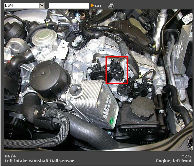
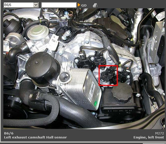
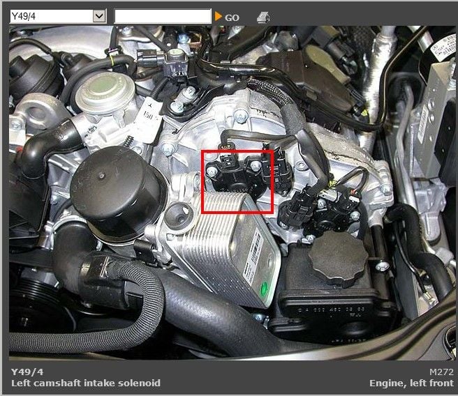
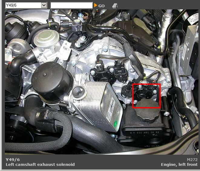
There is no component designated as N10/1 in W164 models but it does have an N10, Front SAM.
Code 0757 refers to B6/4 Left Intake Hall Sensor
Code 0765 refers to B6/6 Left Exhaust Hall Sensor
Code 0070 refers toY49/6 Left Exhaust Solenoid
Code 0282 refers to Y49/4 Left Intake Solenoid
Looking at the M/B diagram shows that voltage and ground actuation is supplied by the ECM, N3/10 and not a fuse.
Attachment shows that M/B had four wiring harnesses fabricated to deal with an UNEXPLAINED problem and with that I can only assume that the harnesses failed on the left side.
#6
Junior Member
Thread Starter
Join Date: Aug 2013
Location: St Paul, Minnesota
Posts: 47
Likes: 0
Received 2 Likes
on
2 Posts
2002 ML320, 2000 eE430 4matic, 2009 ML350 4matic, 1986 Vanagon(subaru powered)
Your diagrams are so helpful. The ALLDATA set is rough. In my humble opinion it appears as if the left bank is fed from the Z738z1 which also feeds the MAF(B2/5) . ALLDATA has it as the ambient intake temp sensor. In contrast the right side is fed through Z738z2 which feeds both solenoids and sensors on the right passenger side. The left side is fed by Z738z1 and I will be damned if I can find it on ALLDATA.
The TSB refers to an additional anti capillary harness (shown by ALLDATA) which was to prevent oil seepage up into harness from the magnets. I have that installed already.
Although since the MAF is not throwing codes, I guess it is safe to assume it is seeing proper voltage off of Z738z1. Can I assume that the problem must lie in the lines past that junction? That is to say since the MAF seems to be getting proper voltage to operate, it is the distribution specific to the sensors and magnets and not the source of Z738z1. Or can the lack of voltage be upstream further? Can a relay or fuse be involved?
I am really scared to start cutting into the harness, it looks pristine. Perhaps I should focus on the connectors and see if there can be shorting in them. Start as far distal as I can.
Thank you for your assistance, I will keep you posted on my progress. It seems as if it should just be a simple swapping out of a failed component, but sadly, with the low voltage to the sensor connectors this may not be the case. Thankfully I have a good side for comparison.
#7
Junior Member
Thread Starter
Join Date: Aug 2013
Location: St Paul, Minnesota
Posts: 47
Likes: 0
Received 2 Likes
on
2 Posts
2002 ML320, 2000 eE430 4matic, 2009 ML350 4matic, 1986 Vanagon(subaru powered)
After looking at the diagram, it looks as if the left bank sensors and magnets are fed off of Z738z2. There is a wire that connects Z738z2 to Z38z1. Could this be the culprit? It would also suggest that fuel injector 4 is not getting voltage also. Would this make sense? If this connection is faulty, both the sensors and magnets on the left side do not receive proper voltage. Any suggestions as to how to find this wire without opening the abdomen, ie. heat shrink shield etc.
How often to wires in these harnesses just up and fail? It has really shaken my belief in superior design and engineering, I was under the assumption that everything was now just plug and play, identify the faulty component and replace. This is a whole different can of worms.
How often to wires in these harnesses just up and fail? It has really shaken my belief in superior design and engineering, I was under the assumption that everything was now just plug and play, identify the faulty component and replace. This is a whole different can of worms.
Trending Topics
#8
MBWorld Fanatic!
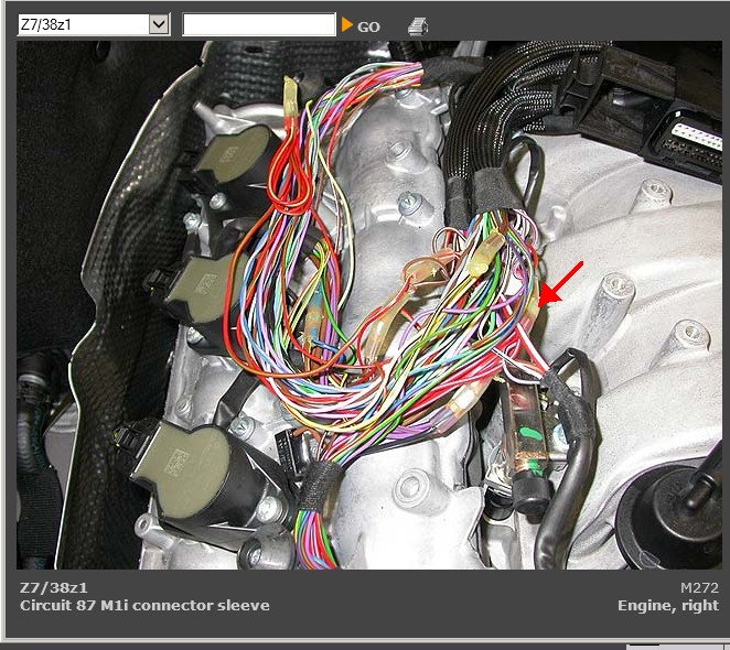
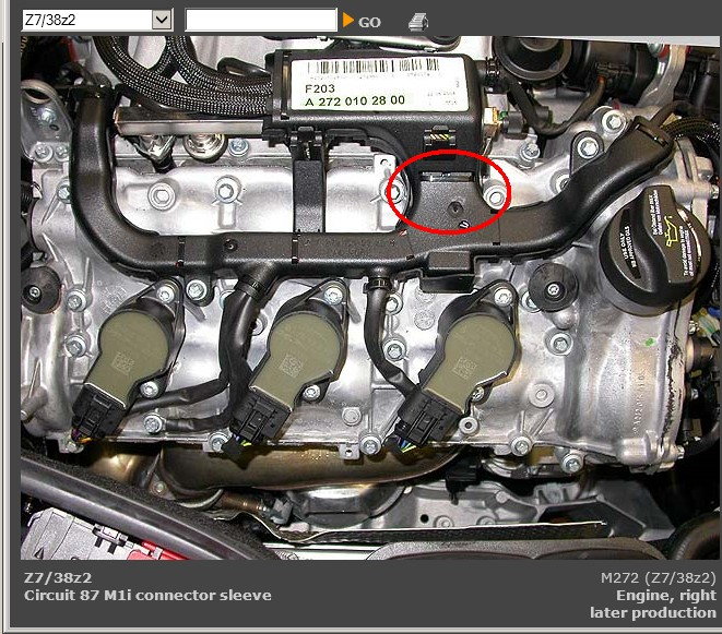
Do not think that there is a MAF Sensor problem. It is the most maligned and thought about component in Merc.vehicles.
It would definitely set a code/s and more importantly it controls both banks. Therefore, it cannot affect a single bank only.
Here are the locations of the "Z" connectors.
How did you find out that your veh. had the harnesses replaced?
#9
Junior Member
Thread Starter
Join Date: Aug 2013
Location: St Paul, Minnesota
Posts: 47
Likes: 0
Received 2 Likes
on
2 Posts
2002 ML320, 2000 eE430 4matic, 2009 ML350 4matic, 1986 Vanagon(subaru powered)
Wow, the photos are great. So much appreciated.
I was mistaken about the MAF, it is powered by the same junction that is powering the right bank (Z738z1) that is good. The bad left bank is powered by a single wire connection to the right bank that is to say that the left bank receives power from (Z738z1) by a single wire that feeds Z738z2. If this connection has failed, both sensors and magnets would not receive voltage. Additionally Injector 4 receives power also on this track. Since I have a misfire code for all left bank cylinders and a general misfire code, could the injector code be buried in these.
The harness was not replaced, only the additional anti capillary harness for the cam magnets, the one referred to in the TSB you provided. I will check for continuity between Z738z1 and z738z2 to see if it confirms. I have not checked voltage on the magnet circuit, since it is grounded by the ECU, would you expect voltage if I probe the supply lead and ground to chassis? Would you also expect continuity between the right and left bank power leads to the sensors since they are all connected to to Z738z1?
And as a final note, the Gods must be telling me something. I dropped a razor knife (box cutter) down in the front of the radiator and believe it or not, punctured the condenser. Standing there listening to the refrigerant slowly escape really hurt. Your helpful responses make it burn just a bit less. Thanks.
#10
Super Member

Wow, the photos are great. So much appreciated.
I was mistaken about the MAF, it is powered by the same junction that is powering the right bank (Z738z1) that is good. The bad left bank is powered by a single wire connection to the right bank that is to say that the left bank receives power from (Z738z1) by a single wire that feeds Z738z2. If this connection has failed, both sensors and magnets would not receive voltage. Additionally Injector 4 receives power also on this track. Since I have a misfire code for all left bank cylinders and a general misfire code, could the injector code be buried in these.
The harness was not replaced, only the additional anti capillary harness for the cam magnets, the one referred to in the TSB you provided. I will check for continuity between Z738z1 and z738z2 to see if it confirms. I have not checked voltage on the magnet circuit, since it is grounded by the ECU, would you expect voltage if I probe the supply lead and ground to chassis? Would you also expect continuity between the right and left bank power leads to the sensors since they are all connected to to Z738z1?
And as a final note, the Gods must be telling me something. I dropped a razor knife (box cutter) down in the front of the radiator and believe it or not, punctured the condenser. Standing there listening to the refrigerant slowly escape really hurt. Your helpful responses make it burn just a bit less. Thanks.
I was mistaken about the MAF, it is powered by the same junction that is powering the right bank (Z738z1) that is good. The bad left bank is powered by a single wire connection to the right bank that is to say that the left bank receives power from (Z738z1) by a single wire that feeds Z738z2. If this connection has failed, both sensors and magnets would not receive voltage. Additionally Injector 4 receives power also on this track. Since I have a misfire code for all left bank cylinders and a general misfire code, could the injector code be buried in these.
The harness was not replaced, only the additional anti capillary harness for the cam magnets, the one referred to in the TSB you provided. I will check for continuity between Z738z1 and z738z2 to see if it confirms. I have not checked voltage on the magnet circuit, since it is grounded by the ECU, would you expect voltage if I probe the supply lead and ground to chassis? Would you also expect continuity between the right and left bank power leads to the sensors since they are all connected to to Z738z1?
And as a final note, the Gods must be telling me something. I dropped a razor knife (box cutter) down in the front of the radiator and believe it or not, punctured the condenser. Standing there listening to the refrigerant slowly escape really hurt. Your helpful responses make it burn just a bit less. Thanks.

#11
Junior Member
Thread Starter
Join Date: Aug 2013
Location: St Paul, Minnesota
Posts: 47
Likes: 0
Received 2 Likes
on
2 Posts
2002 ML320, 2000 eE430 4matic, 2009 ML350 4matic, 1986 Vanagon(subaru powered)
The photos are brilliant. It suggests that both junction splices are on the right passenger side. It should make it a bit less painful to dissect. Are these junctions mechanical splices, ie. multiple wires fed into a single connection? Sort of like wire nut?
#13
Junior Member
Thread Starter
Join Date: Aug 2013
Location: St Paul, Minnesota
Posts: 47
Likes: 0
Received 2 Likes
on
2 Posts
2002 ML320, 2000 eE430 4matic, 2009 ML350 4matic, 1986 Vanagon(subaru powered)
It is opened up, to reveal all of its glory. I am confused with the wiring diagram. According to the diagram, If I add up all the wires going into splice Z738z1 on the diagram, there are 11. There are 2 diamonds labeled Z738z1 are these the same splice? If so, I add up all the injector grey wires (5), the runner to Z738z2 (1), a power to MAF (1), power to sensors (2), power to magnets (2) there are 11 wires joined. For Z738z2 I have a grey to an injector, the runner to Z738z1 (1), power to sensors (2) and power to magnets (2) for a total of 6 wires.
When I look at the splices the wire numbers do not add up. Are the common wires for power to sensors and magnets split elsewhere? I must be missing something in the reading of the diagram.
When I look at the splices the wire numbers do not add up. Are the common wires for power to sensors and magnets split elsewhere? I must be missing something in the reading of the diagram.
#14
Junior Member
Thread Starter
Join Date: Aug 2013
Location: St Paul, Minnesota
Posts: 47
Likes: 0
Received 2 Likes
on
2 Posts
2002 ML320, 2000 eE430 4matic, 2009 ML350 4matic, 1986 Vanagon(subaru powered)
Completely flummoxed. I have found the Z738z1 splice site as shown in the photo. It has RDGY, GYRD, GYBR wires crimped together. The splice has continuity to the connectors for right side camshaft sensors and magnets.
Next up is the Z738z2 splice site. I assume it would have RDBK wires in it from the left side sensors and magnets as per diagram. Plus it would be connected to the Z738z1 splice site by a RDGY wire. No such thing found under the harness cover.
Search deepened, discovered RDBK wires in a splice living underneath the ECU right by the MAF in the track which crosses over back of engine. Here I find 3 RDBK wires and the splice has continuity to the left sensors and magnets. It also has GYYL, GYGN,and GYBL, looking a whole lot like injector wires. All of wires appear to be coming from the left (driver) side of the engine. None are heading back to the Z738z1 splice.
None of this is looking like the diagram I am working off of. Any shared wisdom would be greatly appreciated. Is it possible that the drivers side bank is powered off a splice with different wires?
It seems like it would be straight forward. As per diagram, all connections would seem to be obvious, but it sure don't look like it.
#15
MBWorld Fanatic!
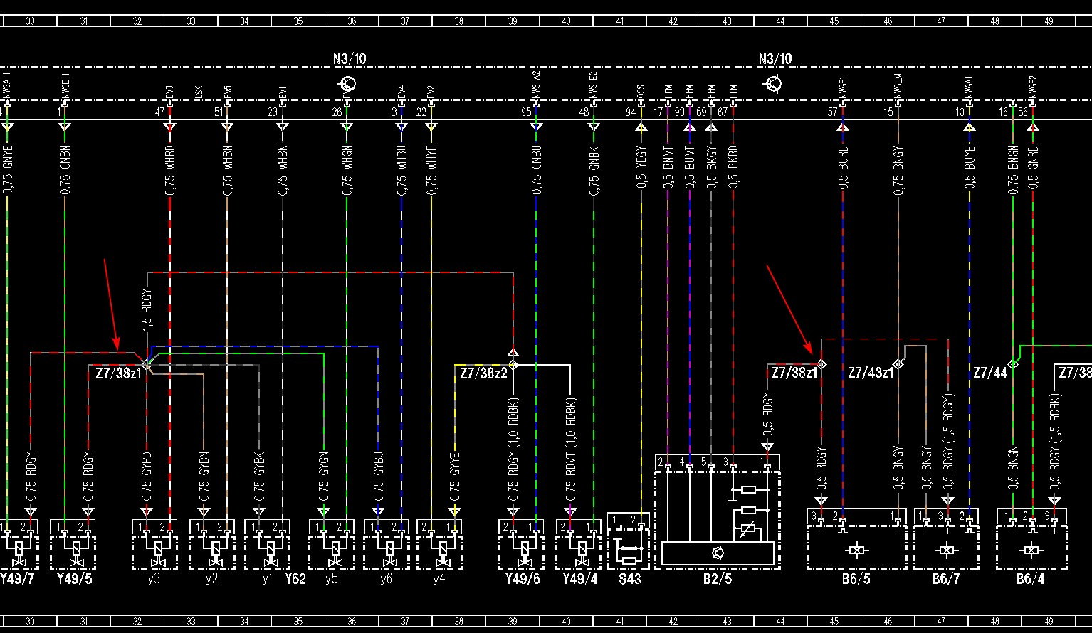
Wolf, I can't see what you are referring to. Please ask specific questions and number them and keep them as short as possible. Don't include them in your paragraphs.
Also note that Z7/38z1 appears in two different sections of the diagram. And no, I cannot print the diag. in color.
#16
Junior Member
Thread Starter
Join Date: Aug 2013
Location: St Paul, Minnesota
Posts: 47
Likes: 0
Received 2 Likes
on
2 Posts
2002 ML320, 2000 eE430 4matic, 2009 ML350 4matic, 1986 Vanagon(subaru powered)
Major,
Sorry, I will try to be as concise as possible. Here is summary of data that I have.
2009 ML350 4matic US version
CEL flashing. Immediate Driveability and starting issues.
Initial Error codes: P0458, P2094, P2092, P2090, P0348, P0393
Codes cleared. Restart Difficult
New Error codes: P0306, P0305, P0304, P2090, P2092, P0348, P0393, P0300
Mercedes error codes: 0645, 0653, 0637, 0070, 0282, 0757, 0765, 0629
Components: Y49/6, Y49/4, B6/4, B6/6
Inspection of Left (Drivers side) Bank: Retrofitted TSB harness present.
Disconnect components. Y49/6, Y4/4, B6/4, B6/6 No oil visible in connectors.
Check magnet resistance: 7.2 ohm each. Same on Right bank. Within spec.
Check continuity to ground of left bank cam sensor connectors (terminal 1 of connector) Both intake and exhaust sensor connectors have continuity to ground. Same on Right bank.
With ignition on, check supply voltage of left bank cam sensor connectors (terminal 3 of connector) Left side connectors measure 2.3 volts. Right side connectors measure 11.7 volts.
Disconnect battery terminals, let sit 1 hr. Reconnect terminals with key in position 2 and wait 10 minutes. Still hardstart and rough running.
Check continuity of cam sensor connectors on left bank, terminals 3, have continuity between them
Check voltage at cam sensors ie. terminals 1 and 3 again: 0.6 volt on both Left bank sensors. 11.7 on both Right bank sensors.
Check continuity between Left and Right bank cam sensors (terminals 3). Continuity not present.
Conclusion: Correct voltage to Left bank sensors and magnets absent. Correct voltage to Right bank sensors present. No continuity between Z738z1 and Z738z2.
What would you check next?
#17
Junior Member
Thread Starter
Join Date: Aug 2013
Location: St Paul, Minnesota
Posts: 47
Likes: 0
Received 2 Likes
on
2 Posts
2002 ML320, 2000 eE430 4matic, 2009 ML350 4matic, 1986 Vanagon(subaru powered)
Afternoon spent sorting through harness with VOM. To summarize:
1. The left bank sensors and magents do not communicate or share voltage with the right bank.
2. There is no connection between Z738z1 and Z7382.
3. The right bank sensors and magnets are supplied by the red/blue wire at X26. It runs over to the right bank and provides power to the ignition on the right bank spliced to purple colored wires to the coils it is than jumped to another splice which feeds the cam sensors and magnets and 2 injectors and the MAF.
4. The left bank sensors and magnets are supplied by the red/black wire at X26. This is spliced to sensors/magnets and purple ignition wires and black wire to suppressor From this splice a RDBK wire runs into harness and connects with the remaining 2 RDBK wires from sensor/magnets in a splice with 3 GY injector wires.
I have good circuits all the way back to X26 for both left and right banks.
This is how I would have designed it.
Questions
1. WTF
2. Where to go from here, upstream of x26 and its feed to the RD/BK and RD/Bu wires that feed the left and right banks respectively. Why would the RDBK wire not have power?
Cheers
#18
Junior Member
Thread Starter
Join Date: Aug 2013
Location: St Paul, Minnesota
Posts: 47
Likes: 0
Received 2 Likes
on
2 Posts
2002 ML320, 2000 eE430 4matic, 2009 ML350 4matic, 1986 Vanagon(subaru powered)
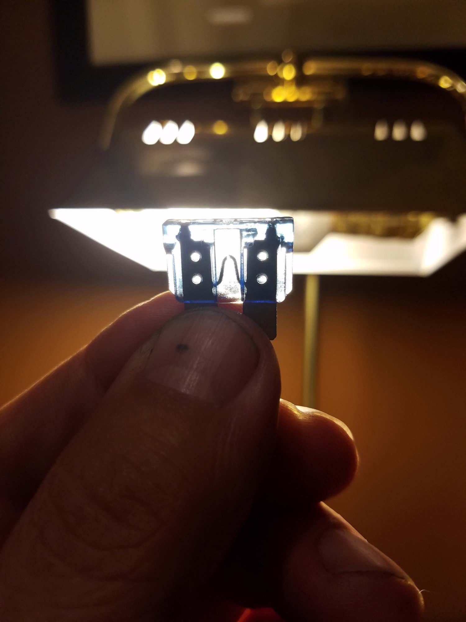
Seems like it would be a no brainer to say that if one bank goes down, that circuit has a failed fuse. ALLDATA DIY says go look at fuse 43 in the back.
No, seems like fuse 105 in the engine compartment box may be bad. Now how would anyone know that when the wiring diagram suggests a jump between left and right banks.
Misfire code was important, no power to coils. Cam sensors and mags error code was important, no power to cam timing. Injectors were most likely not opening as well.
Really disappointing. I will say that the engineering is good, why not have a fused circuit for both sides. My disappointment is not with the engineering, it is with the dissemination of information. Although I am sure I am part of the problem.
The following users liked this post:
nobleeth (06-24-2020)
#20
MBWorld Fanatic!
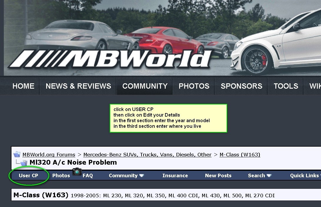
Here is the reason why you and myself have wasted time and effort.
Your profile only states ML320, but your problem concerned a 2009 ML350 4Matic ,neither does it say what eng. you have, 272 or 273 and neither does it say where you live. Here is the response I got for the last person that I asked to UPDATE YOUR PROFILE.
https://mbworld.org/forums/m-class-w...ake-pipes.html
I provided diagrams for a 272 eng where in the diagrams and legends show that there are no fuses whatsoever.
The diagrams and legends for a 273 neg. have fuses, one of which is fuse 105.
So, Please UPDATE YOUR PROFILE in USER CP to include the year and model of your ML including 273 eng. and where you live so future problems will not recur.
#21
Junior Member
Thread Starter
Join Date: Aug 2013
Location: St Paul, Minnesota
Posts: 47
Likes: 0
Received 2 Likes
on
2 Posts
2002 ML320, 2000 eE430 4matic, 2009 ML350 4matic, 1986 Vanagon(subaru powered)
Nothing is a waste of time. You are helpful and generous. I learned a whole bunch about the wiring harness and layout of the vehicle. I have updated my vehicles and location.
I thought 2009 ML350 did have a 272 engine, a petrol V6. We purposely bought a 2009 to avoid the timing chain gear risk. The 273 would be in the ML550? When you say 273 neg, is that a non 273 but not a 272?
Is there just one fuse for the left bank and not the right? Intuitively makes little sense although it does provide 1/2 of engine to let you limp to side of road or back home if its a few blocks. Maybe it does make wonderful sense.
The fat lady has not song yet. I still have to button it all up and hope that the blown fuse is just wear and tear on that teeny little 15A filament.
Cheers
#23
Junior Member
Thread Starter
Join Date: Aug 2013
Location: St Paul, Minnesota
Posts: 47
Likes: 0
Received 2 Likes
on
2 Posts
2002 ML320, 2000 eE430 4matic, 2009 ML350 4matic, 1986 Vanagon(subaru powered)
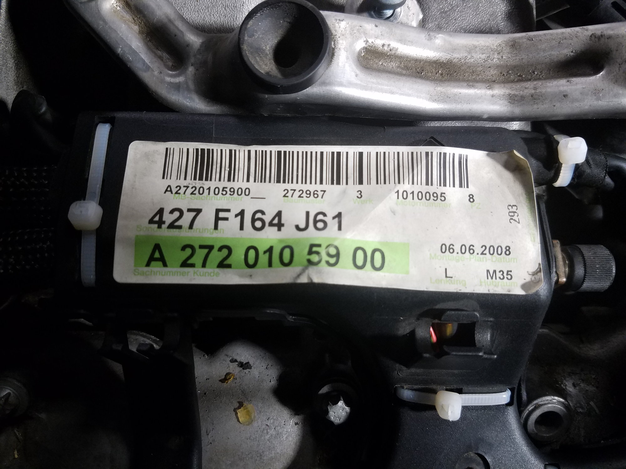
2009 ML350 VIN: 4JGBB86E99A449927 Even better here is the bar code for the harness. We are always so much smarter looking back. What a great way to validate wiring, have a scannable bar code for the version/rev etc. To bad us loners do not have access to the convenience features. But then again, they put the label right on it.
I buttoned it back up, put everything in its place and started it up with bad fuse still in, hard start and runs like crap. Put new fuse in, cleared codes. Running like it used to.
Now if you have any tips on ease of install for a new condenser I would be all ears. I have a dreadful feeling the bumper is going to have to come off.
Thanks again for your attention and assistance. Your contributions are huge.
Cheers.
#24
MBWorld Fanatic!
Wolf, understand that whenever a fuse blows it is as a result of a faulty component/s attached to that fuse or caused by the owner.
Yes, you do have a 272 Eng. which shows that the M/B 272 diagrams are in error as they do not show any fuses. Below is a copy of your DATA card. Print it out and save it.
Yes, you do have a 272 Eng. which shows that the M/B 272 diagrams are in error as they do not show any fuses. Below is a copy of your DATA card. Print it out and save it.
Last edited by Maj. Dundee; 06-21-2018 at 06:21 PM.


