


Understanding Intercooling, Charge-Coolers, Heat Exchangers and Circulation Pumps

Thread Starter
MBWorld Fanatic!


Joined: Nov 2010
Posts: 2,605
Likes: 343
From: Welwyn, Herts, UK
2006 S600
How much heat does a charge cooler have to remove?
When you specify a system to do a job, you normally establish a set of requirements. However, I don’t really have a feel for what the charge cooler is doing, only that I want it to be better. Well, I thought it might be a good idea to understand how much heat it’s trying to dissipate. Figuring out the load on the engine cooling system isn’t too difficult. It’s well known that it dissipates much the same power as the engine produces, so that’s got to be up to about 400kW. That’s dissipated with a 12 litre radiator that runs at about 90oC – around 60oC over ambient. Cooling systems are mature and well-proven, so we know they work.
The charge cooler is a bit more difficult. We normally expect the output of the IC to be 35 - 46oC (pump control temps), but how hot would the intake air be if it wasn’t cooled? Well, when you compress air, it gets hotter, and the pressure increases by more than the volume decreases. If its compressed quickly and doesn’t have time to cool, then it’s an adiabatic compression, for which the equation is:
P1*V1exp1.4 = P2*V2 exp1.4 (where 1.4 is the ratio of constant pressure / constant volume specific heat capacity for air)
This shows that if the intake air is compressed to 2 bar at some temperature, then the volume of the air becomes 61% of the original volume. Knowing the compressed pressure and volume, we now use the general gas equation to get the compressed air temperature:
P1*V1/T1 = P2*V2/T2
Assuming the ambient temp is 300K/27C/80F, the compressed temp becomes 366K/93C/199F. So one bar of boost increases the charge temp by typically 66C just because of the increase in pressure, and that’s an intrinsic change – it doesn’t depend on engine size, speed or power. Having said that, it will probably be higher, as hot turbos tend to heat the intake air even when it’s not being compressed. And if the boost is more than one bar, both the temperature and the mass flow will be higher, so there’s a double whammy for tuned engines.
So how much air does the V12TT use per second? Allowing for a realistic volumetric efficiency, 5000 rpm times 5 litres equals about 200 litres/sec. The density of 2 bar air is about 2g/litre at those temps, so that’s 0.4kg/sec of air flow at full power. The heat capacity of air is 1.0 kJ/kg/C, so assuming the charge cooler needs to drop the temp at least 50C, that means a cooling dissipation of 0.4kJ/s/C x 50C which equals 20kW.
That’s a useful figure to know, and shows that the IC isn’t putting much extra load on the engine rad by heating the incoming air too much. It’s about 20 times less than the engine cooling system – but of course there’s less temp difference available to do it. There’s another interesting comparison to be drawn with engine cooling. The Pierburg documents I linked above suggest that a 200W electric pump is sufficient for a 200kW/270bhp engine, so by the same logic, an IC system should only need one of the small Johnson or DaviesCraig pumps. An 80W Meziere or Pierburg pump sounds overkill - except that IC systems are definitely low-temperature, high-resistance, systems.
Nick
Last edited by Welwynnick; Apr 22, 2013 at 08:07 AM.
Thread Starter
MBWorld Fanatic!
Joined: Nov 2010
Posts: 2,605
Likes: 343
From: Welwyn, Herts, UK
2006 S600
Now, what about the IC coolant? Looking at the pump characteristics chart, it seems the normal operating point is around 5gpm/20lpm at 30kPa. That’s just a third of a kg/sec, and even the best pumps only get that up to � kg/sec. So the coolant mass flow rate happens to be very similar to the air mass flow rate – though we do need the reduction in air temp to be greater than the increase in water temp. The heat capacity of water is 4.18kJ/K/kg, so the coolant has a capacity of about 1.4kW/K – perhaps 2kW/Kfor a big pump. At full power, that means a temp increase of 20/1.4 or 14C, or around a quarter of the air temp reduction, as you’d expect from the flow rates and heat capacities. I’m not certain, but from a few articles I’ve read I think that’s pretty similar to the temp drop across the engine radiator. Most people expect to see 20F across any radiator, whether it’s on a go-cart or a nuclear power station.
My first impression is that the stock IC system was designed against the requirements of the stock engine, at best.
Second, I hadn’t considered that tuning would increase the cooling requirements exponentially – due to the collective increases in intake air pressure, temperature, density and flow rate.
Third, I’m also surprised that the heat carrying capacity of the water isn’t higher – if it was comfortably high enough, the temp delta might be a few degrees, but 14C sounds kind of marginal for a low temp system.
Fourth, in my earlier reasoning I hadn’t considered how high the intake air mass flow rate - and hence the cooling requirements - would be. If the coolant rises 14C in one cycle, that doesn’t give it much margin or storage capacity – just a few seconds at WOT and it’s all heated up.
Finally, none of this considers the heating contribution from the turbos themselves – aside from the compressing of the air, that is. I don’t know what that would be, but it will only make the IC system’s job harder.
Nick
Last edited by Welwynnick; Apr 22, 2013 at 08:14 AM.
Thread Starter
MBWorld Fanatic!
Joined: Nov 2010
Posts: 2,605
Likes: 343
From: Welwyn, Herts, UK
2006 S600
Here's a rather scrappy scratchpad of links and ideas, with a bit more evidence to support the requirements and implementation of charge coolers.
http://f10.m5post.com/forums/showthread.php?t=588858
Interview with, J�rgen Poggel, Head of Engine Development at BMW M Power GmbH
The charge air exiting the compressor measures as much as 130 �C.
The turbo-chargers are mounted in the middle of the V, with the inlet manifolds where the exhaust would be. Bizzare.
The M5 has a cross-over exhaust manifold where each turbo takes exhaust from both cylinder banks.
The temperatures of the exhaust manifolds and turbochargers can be as high as 1000 �C and the oil hits 200 oC.
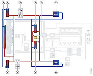
Low temperature circuit for cooling the charge air and the Digital Motor Electronics:
A Coolant radiator
B Additional coolant radiator
C Electric coolant pump for cylinder bank 1
D Charge air cooler for cylinder bank 1
E Expansion tank
F DME cylinder bank 1
G DME cylinder bank 2
H Charge air cooler for cylinder bank 2
I Electric coolant pump for cylinder bank 2
J Additional coolant radiator
The charge cooler has two CWA 50 pumps and THREE heat exhangers.
Two of them measure 25 x 25 cm, and the other looks like 60 x 25 cm.
http://www.realoem.com/bmw/showparts.do?model=LX91&mospid=55181&btnr=17_0617& hg=17&fg=30
http://www.michelecaroli.com/autopar...PORSCHE&tpr=S3
Porsche 911 Turbo air-air coolers measure 2 x 325 x 220 x 80 mm = 11.4 litres, equivalent to 5.7l charge cooler plus 5.7l HE.
These are the largest stock IC's I've found. The Panamera Turbo and Audi Q7 IC's are slightly smaller - about 10l.
http://www.autospeed.com/cms/A_110200/article.html
The Corvette ZR1's LS9 Supercharged Small Block
Maximum boost pressure is 10.5 psi (0.72 bar).
Because the pressurized air is hotter than naturally aspirated air, the LS9 employs a liquid-to-air charge cooling system to reduce inlet air temperature after it exits the supercharger – reducing the inlet air temperature by up to 78 degrees C (140 F).
http://www.are.com.au/Big%20HP/Craig...sAWComorig.htm
http://www.are.com.au/Big%20HP/Craig...owww6pages.pdf
Extreme turbo-charging: 1895 whp from 6997cc @ 8000 rpm @ 40psi boost
Air intake mass flow: 2 kg/s
IAT: 230 oC
Charge cooling requirement: 409 kW
http://stratifiedauto.com/wordpress/...azdaspeed6.jpg
Two dyno runs on a Mazda 6 turbo:
230 bhp @ 88 oF ambient
262 bhp @ 66 oF ambient
12 oC air temp reduction gives 13 % power increase.
Using PV = nRT, the temp increase gives a 6.5% reduction in air density.
The remaing 6% power loss is probably down to ignition retard or boost reduction.
http://f10.m5post.com/forums/showthread.php?t=588858
Interview with, J�rgen Poggel, Head of Engine Development at BMW M Power GmbH
The charge air exiting the compressor measures as much as 130 �C.
The turbo-chargers are mounted in the middle of the V, with the inlet manifolds where the exhaust would be. Bizzare.
The M5 has a cross-over exhaust manifold where each turbo takes exhaust from both cylinder banks.
The temperatures of the exhaust manifolds and turbochargers can be as high as 1000 �C and the oil hits 200 oC.
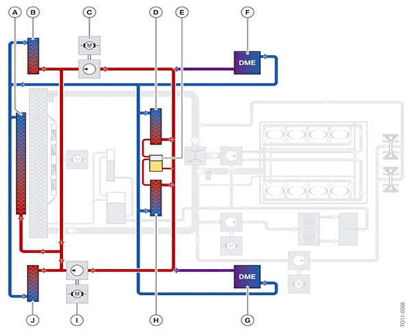
Low temperature circuit for cooling the charge air and the Digital Motor Electronics:
A Coolant radiator
B Additional coolant radiator
C Electric coolant pump for cylinder bank 1
D Charge air cooler for cylinder bank 1
E Expansion tank
F DME cylinder bank 1
G DME cylinder bank 2
H Charge air cooler for cylinder bank 2
I Electric coolant pump for cylinder bank 2
J Additional coolant radiator
The charge cooler has two CWA 50 pumps and THREE heat exhangers.
Two of them measure 25 x 25 cm, and the other looks like 60 x 25 cm.
http://www.realoem.com/bmw/showparts.do?model=LX91&mospid=55181&btnr=17_0617& hg=17&fg=30
http://www.michelecaroli.com/autopar...PORSCHE&tpr=S3
Porsche 911 Turbo air-air coolers measure 2 x 325 x 220 x 80 mm = 11.4 litres, equivalent to 5.7l charge cooler plus 5.7l HE.
These are the largest stock IC's I've found. The Panamera Turbo and Audi Q7 IC's are slightly smaller - about 10l.
http://www.autospeed.com/cms/A_110200/article.html
The Corvette ZR1's LS9 Supercharged Small Block
Maximum boost pressure is 10.5 psi (0.72 bar).
Because the pressurized air is hotter than naturally aspirated air, the LS9 employs a liquid-to-air charge cooling system to reduce inlet air temperature after it exits the supercharger – reducing the inlet air temperature by up to 78 degrees C (140 F).
http://www.are.com.au/Big%20HP/Craig...sAWComorig.htm
http://www.are.com.au/Big%20HP/Craig...owww6pages.pdf
Extreme turbo-charging: 1895 whp from 6997cc @ 8000 rpm @ 40psi boost
Air intake mass flow: 2 kg/s
IAT: 230 oC
Charge cooling requirement: 409 kW
http://stratifiedauto.com/wordpress/...azdaspeed6.jpg
Two dyno runs on a Mazda 6 turbo:
230 bhp @ 88 oF ambient
262 bhp @ 66 oF ambient
12 oC air temp reduction gives 13 % power increase.
Using PV = nRT, the temp increase gives a 6.5% reduction in air density.
The remaing 6% power loss is probably down to ignition retard or boost reduction.
Last edited by Welwynnick; May 5, 2013 at 07:31 PM.
Thread Starter
MBWorld Fanatic!
Joined: Nov 2010
Posts: 2,605
Likes: 343
From: Welwyn, Herts, UK
2006 S600
By way of getting a feel for what charge coolers do, and what makes them tick, I've been expanding on some of my earlier sums. I used some simple assumptions and thermodynamics equations to estimate how much thermal energy and power was involved, but that was only a baseline. Upgraded intercooling is often wanted for re-mapped engines, but I said before that re-mapping makes things exponentially harder for the IC. But how much harder? I ran the sums for a range of absolute MAP starting with ambient.
P,V,T,D are absolute pressure, volume, temperature, density & 1 = ambient, 2 = compressed
P1. . . . . . V1 . . . . . T2/T1 . . . T1 . . . . T1 . . . . D1
1.0 bar . . 1.0000 . . 1.0000 . . 300K. . . 27C . . . 1.000
P2. . . . . . V2 . . . . . T2/T1 . . . T2 . . . . T2 . . . . D2
1.5 bar . . 0.7485 . . 1.1228 . . 337K. . . 64C . . . 1.336
1.7 bar . . 0.6788 . . 1.1676 . . 350K. . . 77C . . . 1.473
2.0 bar . . 0.6095 . . 1.2190 . . 366K. . . 93C . . . 1.640
2.5 bar . . 0.5197 . . 1.2993 . . 390K. . . 117C . . 1.924
3.0 bar . . 0.4562 . . 1.3687 . . 410K. . . 137C . . 2.192
3.7 bar . . 0.3913 . . 1.4555 . . 436K. . . 164C . . 2.556
V2 = V1*(P2/P1)exp-0.71428 (negative reciprocal gamma)
T2/T1 = (P2/P1)*(V2/V1)
D2 = D1*(V1/V2)
These figures show what happens to compressed intake air if you don't cool it down. The density column, which is normalized to ambient, is particularly interesting as it tells us how much extra air mass flow you get for the extra boost pressure. If you could keep the IAT down to ambient, D2 would be the same as P2, but it illustrates the loss of charge density and presumably torque caused by the IAT increase.
Consider the case of a tuned turbo with the boost turned up from 1.0 bar to 1.5 bar. Relative to stock, the mass flow goes up by 1.924/1.640 or 17%, but the air temp goes up 90/66 or 36%. Therefore the total extra thermal load power on the charge cooler goes up by 1.17 x 1.36 or 60% over stock.
That 17% extra air mass flow probably translates quite directly into a 17% increase in torque, from say 600 to 700 lb/ft, which sounds about right. Turbo tuning doesn't increase power as much as torque due to turbo throttling and volumetric efficiency, so real world peak power probably goes up 10% from say 540 to 590 bhp.
Therefore a 10% power increase costs you a 60% increase in charge cooler thermal loading. That's what I meant by exponetial increase. So for a typical tuned car, the IC needs to remove 20kW x 1.6 = 32kW heat power. Divide that by 1.4kW/C stock cooling capacity gives 23C, or 41F, which is the coolant temp increase in one pass through the IC. In practice it's impossible because it exceeds the temperature budget, and the coolant temp and the IAT have to rise. It's about twice as high as it should be for a high temperature cooling system, and much too high for a low temp system, where the coolant is close to ambient temp.
That's why I believe the stock IC, for tuned cars in particular, needs to be heavily upgraded. Of course most car manufacturers have figured this out now, such that the current Golf 1.6 Diesel appears to have greater cooling capacity than the S600TT. Truck makers have known this for a long time. By a process of engineering evolution, that's simply what's needed to make turbos work.
Nick
Last edited by Welwynnick; May 6, 2013 at 06:41 AM.
Thread Starter
MBWorld Fanatic!
Joined: Nov 2010
Posts: 2,605
Likes: 343
From: Welwyn, Herts, UK
2006 S600
As I see it, the turbos put energy into the intake charge in three ways:
The figures in yesterdays post don't quite match up - the IAT is higher in practice than (1) predicts, so I assume that (2) is a significant effect. It must be a function of turbo heating under load, and I don't really have a handle on it. Maybe empirical evidence is more relevent that analysis - ie: just go measure it.
The useful part of what turbos do is (3). That's what we need them to do, and when we try to get rid of (1) and (2) its just throwing away waste. however, I didn't have a feel what the useful power was, so here it is for interest. I calculated this for circulation pumps with a representative example:
Nick
- Heating the air by compressing it (as above)
- Heating the air because the turbos are hot (don't understand yet)
- Increasing the pressure of the air
The figures in yesterdays post don't quite match up - the IAT is higher in practice than (1) predicts, so I assume that (2) is a significant effect. It must be a function of turbo heating under load, and I don't really have a handle on it. Maybe empirical evidence is more relevent that analysis - ie: just go measure it.
The useful part of what turbos do is (3). That's what we need them to do, and when we try to get rid of (1) and (2) its just throwing away waste. however, I didn't have a feel what the useful power was, so here it is for interest. I calculated this for circulation pumps with a representative example:
- Power = force x displacement / time = pressure x area x velocity = pressue x flow rate
- Water Power = 40 kPa x 30 l/min = 40 kPa x 0.5 l/sec = 20 W
- Air Power = 100 kPa x 200 l/sec = 20 kW (or 30kW @ 1.5 bar)
Nick
Last edited by Welwynnick; May 6, 2013 at 06:01 AM.
Thread Starter
MBWorld Fanatic!
Joined: Nov 2010
Posts: 2,605
Likes: 343
From: Welwyn, Herts, UK
2006 S600
I'll have something really worthwhile to post about in a few days, but for now I just had an idea to put down on paper.
At the beginning of the thread I supposed that the cooler and the HE in a charge cooling system ought to follow in the tracks of well-developed air-air coolers - they should have a similar volume. When you look at the insides of an air-air cooler, the total combined volume of the cooler occupied by the air that's being cooled is generally similar to that occupied by the air that's doing the cooling. That sounded like a reasonable starting point to me.
Then today I wondered if there was another, technologically mature precedent for the optimum design of heat transfer systems. Something where heat is taken from inside the car and disspiated outside the car? Air conditioning of course! There's an evaporator "inside" the car that absorbs the heat, and a condenser "outside" that dissipates it. There's a heat pump involved of course, but I think the principle is similar.
I already said in the first post that AC condensers had matured and converged on a consistent design between systems. In most cars, the condenser has a similar area to the engine radiator - around 600 x 450mm - and is almost invariably 16mm thick. The volume of the core is typically between 3 - 4 litres.
But what about the evaporator in the HVAC system? If my principle has some credibility, then the evaporator will also have a similar volume. So I did a survey of a large number of evaporators today, and found that they're similar in size to the heater matrix, but rather thicker. We're talking about half the width and height of the condensor - around 300 x 200mm - but much thicker - about four times as think in fact, about 65mm. The Audio A6 is an exception that proves the rule, having a huge 6 litre core, but otherwise they're similar. At first I thought the W220 had an unusually small evaporator for any car, let alone a luxury car, but then I realised I was looking at the seat cooling HE, which only measures 2.2 litres. The cabin HE is normal size.
They don't vary much from car to car, and it seems that everyone has figured out the best way to do air conditioning efficiently these days. Its mature technology and well-developed. And it just happens to have the same solution as my conjecture, where the cooling HE has about the same volume as the cooled HE. Granted, they're a different shape, just as they are with charge cooling, but I think the volume of the core is key.
I never thought that before, but it is another reasoned argument why the HE should be as big as the cooler, rather than a fraction of its size.
Don't worry if this is getting boring, the best is yet to come....
Nick
Junior Member
Joined: Jan 2013
Posts: 60
Likes: 1
'06 S65 AMG W220 12.31@119_MPH (Stock)
Nick,
What do you think of the Killer Chiller system. They've been around for a while. They're made for Ford Mustang and Lighting, but I'm sure it can be adapted to our cars somehow. I think someone has it installed on an E55.
http://www.killerchiller.com/system_2_page.htm
https://mbworld.org/forums/w211-amg/...gree-iats.html
MB World Stories
The Best of Mercedes & AMG

Manual Mercedes? 6 Times Sindelfingen Let Drivers Have All The Fun
Verdad Gallardo
Mercedes SLR McLaren 722 S Is Extremely Rare Example Modified by McLaren
Verdad Gallardo
8 Classic Boxy Mercedes Designs That Have Aged Like Fine Wine
Verdad Gallardo
Flawlessly Restored Mercedes 190E Evo II Heads to Auction
Verdad Gallardo
Electric Mercedes C-Class Unveiled: 11 Things You Need to Know
Verdad Gallardo
Mercedes EQS Gets A Major Update: Everything You Need to Know
Verdad Gallardo
5 Underrated Mercedes-Benz Models That Don't Get the Love They Deserve
Verdad Gallardo
Mercedes 300D Has Pushed Well Past 1 Million Miles and It Ain't Stopping
Verdad Gallardo
10 Most Reliable Mercedes-Benz Models You Can Buy Used
Verdad Gallardo
Thread Starter
MBWorld Fanatic!
Joined: Nov 2010
Posts: 2,605
Likes: 343
From: Welwyn, Herts, UK
2006 S600
I think a few people have installed Killer Chillers in supercharged Mercs, but I’m not sure what the practical benefit is, and have some questions.
What’s the installation – use with a heat exchanger, or with a trunk tank?
What’s the application – street or strip?
What’s the objective – lower temps than passive cooling, or lower than ambient?
Continuous or intermittent use?
Stock or tuned?
I doubt that a Killer Chiller has much capacity compared with a conventional system, I think a charge cooler needs to dissipate more heat power than the AC system can cope with. We’re probably talking about a few kW vs a few tens of kW. It’s only likely to be effective for occasional strip use where you want to get the IATs below ambient. You’d probably have to use a cold water tank to "store" the cooling capacity. That heat has to go somewhere, and with a Killer Chiller it ends up being dissipated by a 16mm thick condenser – I’d rathe rit was dissipated by a 40mm thick HE. Also, how do you know that the engine power gain from a Killer Chiller isn’t offset by the extra load on the AC compressor? Or do you run the AC for a while to cool the trunk tank, then turn it off for a run?
There are some weak points in the stock IC system, and I’m trying to find simple, efficient and effective upgrades that keep the car as a daily driver, and as close to stock as possible. I want it fast – yes, but also comfortable, quiet, reliable, practical and reasonably economical too. If I justwanted fast, I’d remove all the seats and trim. I’ve done that before, and great fun it was too, but I’ve moved on since then.
If somebody wanted to add a Killer Chiller to a stock system and keep the HE, then the mods I’m talking about here would be complimentary to that, and work well together. A better pump would probably help with the added coolant flow resistance from the KC. If you want to use a trunk tank, I think that’s a completely different path to take.
Nick
Last edited by Welwynnick; May 9, 2013 at 02:27 PM. Reason: typos

Member
Joined: Jun 2010
Posts: 116
Likes: 1
2007 s600
Nick
So based on your research so far, what pump would you recommend with an upgraded heat exchanger? Is the Johnson CM30 enough to move around the coolant, or do we need a pump with a higher flow rate.
Thanks.
So based on your research so far, what pump would you recommend with an upgraded heat exchanger? Is the Johnson CM30 enough to move around the coolant, or do we need a pump with a higher flow rate.
Thanks.
Thread Starter
MBWorld Fanatic!
Joined: Nov 2010
Posts: 2,605
Likes: 343
From: Welwyn, Herts, UK
2006 S600
No, I think the CM30 is quite unsuitable, even for stock systems. There's no reason to chose that over either of the Bosch pumps.
I'm leaning towards using one of the Pierburg pumps that are used by BMW, and I've just bought one.
nick
I'm leaning towards using one of the Pierburg pumps that are used by BMW, and I've just bought one.
nick
Member
Joined: Jun 2010
Posts: 116
Likes: 1
2007 s600
Nick
I have an extra CM30 lying around. What would happen to the flow rate if I was to add this extra pump before the heat exchanger and have it turn on with the other pump simultaneously. I would speculate the flow and pressure to increase twofold. Any thoughts or comments.
Thanks.
I have an extra CM30 lying around. What would happen to the flow rate if I was to add this extra pump before the heat exchanger and have it turn on with the other pump simultaneously. I would speculate the flow and pressure to increase twofold. Any thoughts or comments.
Thanks.
Thread Starter
MBWorld Fanatic!
Joined: Nov 2010
Posts: 2,605
Likes: 343
From: Welwyn, Herts, UK
2006 S600
Good question, I hadn't thought about that.
If you have two similar pumps, you will definitely get more flow, though not twice as much, as that corresponds to maybe eight times more pumping power. Power equals pressure times flow, and pressure is proportional to flow squared.
If you combine two different pumps, its a bit more unpredictable. If the bigger pump gives more flow as installed than the small pump does open outlet, then the small pump will actually slow the bigger pump.
Look at the pump comparison chart in my April 21 post, and compare the Bosch and Johnson pumps. The installed performance of the Bosch pump is where the red curve crosses the Charge Cooler Resistance curve (about 22l/min @ 37kPa for the -010 pump). That point corresponds to a flow rate LOWER than where the CM30 curve crosses the horizontal axis (30l/min) - therefore the Johnson won't be slowing down the Bosch, and it should ADD to the circulation flow rate.
How much it will add is difficult to predict. I've never done this before. I think you could add the Johnsons' flow rate to the Bosch flow rate and generate a combined pressure/flow curve, and see where that curve crosses the Charge Cooler Resistance curve. I think that would be the new flow rate. The Bosch flows quite a lot more than the Johnson, and the resistance curve is quite steep, so the flow gain won't be that great. I'd estimate the flow would go up from 22 to 24 l/min.
Nick
Member
Joined: Jun 2010
Posts: 116
Likes: 1
2007 s600
Nick
If you double the size of the front mount heat exchanger and double the size of the air to water intercoolers would you think a double pump setup would be more logical?
In theory you are increasing the cooling capacity two fold and therefore would need extra push in volume. I do believe that a double pump setup would move more liquid and put less of a stress on just a single pump.
Curious as to what you think.
Thread Starter
MBWorld Fanatic!
Joined: Nov 2010
Posts: 2,605
Likes: 343
From: Welwyn, Herts, UK
2006 S600
Yes, I think that would make a lot of sense. If you want to double the flow, you need to double the capacity of everything, not just the pump.
You can always use brute force and ignorance, but increasing the pressure in itself doesn't help - its flow that counts. And if you want to increase flow, I think the best way is both the pump and the HE.
I doubt that the charge coolers themselves cause much flow restriction, as they have lots of tubes, but the more the merrier!
Only thing with uprating the charge coolers is what to do with the air filters. If you lose the cold air intakes, you undo a lot of the work with the improved cooling. I'm not sure how hot is the air in the engine compartment, but all of it has come through the radiators, so I bet its pretty warm.
Nick
Thread Starter
MBWorld Fanatic!
Joined: Nov 2010
Posts: 2,605
Likes: 343
From: Welwyn, Herts, UK
2006 S600
OK, this is all very interesting, but where's this thread heading?
We're not there yet, but this is the next piece of the jig-saw:
I first posted this in another forum, but it seemed to go unnoticed. I think that many charge-cooled turbo cars use continuous-running circulation pumps - Lotus Carlton, Jaguar XJR & XKR etc, and the blown Mercs seem to me to be at a disadvantage with their modest, thermostatic pumps. When looking for other pump options, like many others I found the Davies Craig pumps, especially the EWP 80 and 115. What was particularly interesting about Davies Craig was the pump controller. This implemented thermostatic control not only of the big Davies Craig water pumps, but any EWP in principle, and allowed you to modulate the pump output and adjust the target temperature in a fairly crude way. The BMW circulation and cooling pumps discussed in the earlier post are more effective and controllable, but the only way to control them is with a BMW ECU. That is (as they say on Top Gear) until now....
Last year a small German company called Tecomotive developed an electric pump controller (the tinyCWA) specifically for the Pierburg circulation and cooling pumps used by BMW: the CWA 50, 100, 200 & 400. With a suitable temperature sender, this enables thermostatic control of the BMW pumps, so that any car can benefit from their efficiency and flexibility. Like the Davies Craig controller, you can adjust the target coolant temperature, but it has much more flexible controls. Here's the web page and here's the users manual. The pump can set to run continuously at variable speeds, it can be run manually, and the controller can display the coolant temp or the pump speed. This seems to be intended for engine cooling, but I believe it can be used with the 50W and 100W circulation pumps as well.
Engine speed independent cooling
Integrated cooling fan controller
No more overheating at engine idle
No thermostat necessary
Quick and predictive control algorithm
Delayed shutdown
An automotive controller for Pierburg’s (BMW) electric water pumps CWA200
The Tecomotive “tinyCWA” is able to control the CWA200 electric water pump (eWP) in the appropriate manner.
It is suitable for cars or any other thing where smart cooling is required.
When activated the controller is measuring the current coolant temperature and the
rate of increase with the connected temperature sensor.
With this data it then calculates the appropriate water flow and sends a signal to the pump where the internal pump electronics then set it to the right speed.
This way you will always have the right pump speed for any circumstances.
We developed this product with very special attention to quality, operational safety, ease of use and a very nice appearance.
The compact and anodized aluminum case measures only 51x51x13mm. (2x2x1/2inches)
You can find more precise information about the operation, installation and use in the manual
Features:
- Simple to set up with only one rotary switch
- Choose your favorite target temperature in six steps from 75�C to 100�C (167�F to 212�F)
- LED display shows the current pump speed or rough coolant temperature
- Compact and robust anodized aluminum case
- Relay output for the radiator fan (recommend to use)
- Delayed shutdown of the pump and the fan after ignition turned offManually control the pump speed (e.g. for bleeding or testing)
Thread Starter
MBWorld Fanatic!
Joined: Nov 2010
Posts: 2,605
Likes: 343
From: Welwyn, Herts, UK
2006 S600
Sometimes I think our cars are unfathomably complicated, yet sometimes I realise you only need to understand a little bit about how they work to realise that there's no black art or mystery to them.
I had assumed that the charge coolers themselves were simple cross-flow heat exchangers. The air flows inwards towards the center of the engine, and the coolant flows cross-wise. But it only takes a simple inspection to realise that its not like that. The charge coolers are obviously dual-pass coolers, since the water inlet and outlet are on the same side - at the rear of the coolers. Look closely at the coolers and you can see diagonal weld-lines at the front, that correspond to a shallow triangle-shaped header tank to turn the coolant round.
They're not like dual pass radiators, where each pass is parallel to the air flow - two coolant streams cross two different air streams. The V12TT coolers are series dual pass, where a single air stream flows across the two coolant streams. More than that, they're counter-flow heat exchangers, where the air and the water (kind of) flow in opposite directions. The MB implementation is like two coolers in series - a high temp cooler and a low-temp cooler. The hot air flows into the hot cooler first, then into the cold cooler. The cold water, by contrast, flows into the cold cooler first, then into the hot cooler.
This is how the best heat exchangers work, and it allows the air coming out of the cooler to be at a lower temperature than the water coming out of the cooler, which wouldn't be possible in a single cross-flow configuration. There are three main types of heat exchanger - parallel flow, cross flow and counter-flow - and these are a hybrid cross/counter flow configuration. Although this means there's more air and coolant resistance, both the air and coolant paths are still pretty short, and I think these coolers have an advantage over other coolers - and definitely over all air-air intercoolers.
Nice.
Thread Starter
MBWorld Fanatic!
Joined: Nov 2010
Posts: 2,605
Likes: 343
From: Welwyn, Herts, UK
2006 S600
Thanks for bearing with me; this is where it starts to get interesting.
I contacted Tecomotive, the manufacturer of the tinyCWA Pierburg cooling pump controller. Like the Davies Craig pump controller, theirs is designed for engine cooling, so the temp range is appropriate for that application - 75 to 100 deg C. So I asked Tobias Mucke at Tecomotive if they could modifiy their controller to work over a temp range more appropriate for a low temp charge cooler system. And guess what - they said yes!
The changes are implemented in firmware, and are quick and easy to implement. There are sixteen programmed modes of operation (O to F), and Tecomotive offered to set any program I wanted. The stock controller has normal and pulsed modes, which are applicable to thermostat controlled cooling systems, and are deleted for charge cooling. You can see the stock Tecomotive user manual here:
http://www.tecomotive.com/download/manual_tinyCWA.pdf
After lots of questions and emails, we arrived at the following charge cooler program:
Pos. Mode TargetTemperature Description
0 Testmode - Pump Off / Fan Off
1 Testmode - Pump to min. rev. / Fan Off
2 Testmode - Pump to 50% / Fan Off
3 Testmode - Pump to 100% / Fan On
4 Normalmode 0�C The controlled temperature range is plus minus 5�C / 9�F from the currenttarget temperature.
5 Normalmode 5�C
6 Normalmode 10�C
7 Normalmode 15�C
8 Normalmode 20�C
9 Normalmode 25�C
A Normal mode 30�C
B Normal mode 35�C
C Normal mode 40�C
D Normal mode 45�C
E Normalmode 50�C
F Normalmode 55�C
In addition to these operating and test modes (which are great for installation and bleeding), there are lots of advanced modes to make the pump do whatever you want. You can set the pump to work under thermostatic control, or at fixed speeds, or permanantly full on or full off. I think the best mode is with a fixed minimum speed, so the pump is spinning slowly all the time (and you can set the minimum speed to whatever you want).
The knob on the controller sets the mode - essentially the target temperature - and the LED display gives an indication of the actual temperature, or the actual pump speed - whichever you chose to display. The displayed temp range is also customized to match the charge cooler target temp range. Its really a very clever little box; so many tunes to play. Its a new derivative called the Charge Cooler Special, and there's a revised user manual that I could send to anyone interested.
And I've got the first one!
Nick
Last edited by Welwynnick; Jun 2, 2013 at 04:34 AM.
Junior Member
Joined: Jan 2013
Posts: 60
Likes: 1
'06 S65 AMG W220 12.31@119_MPH (Stock)
I think a few people have installed Killer Chillers in supercharged Mercs, but I�m not sure what the practical benefit is, and have some questions.
What�s the installation � use with a heat exchanger, or with a trunk tank?
What�s the application � street or strip?
What�s the objective � lower temps than passive cooling, or lower than ambient?
Continuous or intermittent use?
Stock or tuned?
I doubt that a Killer Chiller has much capacity compared with a conventional system, I think a charge cooler needs to dissipate more heat power than the AC system can cope with. We�re probably talking about a few kW vs a few tens of kW. It�s only likely to be effective for occasional strip use where you want to get the IATs below ambient. You�d probably have to use a cold water tank to "store" the cooling capacity. That heat has to go somewhere, and with a Killer Chiller it ends up being dissipated by a 16mm thick condenser � I�d rathe rit was dissipated by a 40mm thick HE. Also, how do you know that the engine power gain from a Killer Chiller isn�t offset by the extra load on the AC compressor? Or do you run the AC for a while to cool the trunk tank, then turn it off for a run?
There are some weak points in the stock IC system, and I�m trying to find simple, efficient and effective upgrades that keep the car as a daily driver, and as close to stock as possible. I want it fast � yes, but also comfortable, quiet, reliable, practical and reasonably economical too. If I justwanted fast, I�d remove all the seats and trim. I�ve done that before, and great fun it was too, but I�ve moved on since then.
If somebody wanted to add a Killer Chiller to a stock system and keep the HE, then the mods I�m talking about here would be complimentary to that, and work well together. A better pump would probably help with the added coolant flow resistance from the KC. If you want to use a trunk tank, I think that�s a completely different path to take.
Nick
Nick,
In your hypothesis, have you put into any consideration that the Killer Chiller system has a slight advantage with the help of R-134a freon with a boiling point of about -15 *F vs. water at +212 *F at atmospheric pressure?
I will try to answer some of your questions as best as I can:
What�s the installation � use with a heat exchanger, or with a trunk tank? -You can use it with or without heat exchanger. For better result, use it with HE but have the coolant flow into the HE first then Killer Chiller then intercoolers. KC can chill the coolant to below ambient temps and you wouldn't want it to get reheated by the HE. If you're not planning to use HE, I would highly recommend a trunk tank. This way you can cool down your coolant and have it in reserve while driving normally and when needed for those special situation, you'll be ready.
What�s the application � street or strip? -Either or.
What�s the objective � lower temps than passive cooling, or lower than ambient? -To get temps lower than ambient which is not possible with a straight up HE set up no matter how big the HE you can put on the car.
Continuous or intermittent use? -If use with HE, can be continuous.
Stock or tuned? -Either or.
I doubt that a Killer Chiller has much capacity compared with a conventional system, I think a charge cooler needs to dissipate more heat power than the AC system can cope with. We�re probably talking about a few kW vs a few tens of kW. It�s only likely to be effective for occasional strip use where you want to get the IATs below ambient. You�d probably have to use a cold water tank to "store" the cooling capacity. That heat has to go somewhere, and with a Killer Chiller it ends up being dissipated by a 16mm thick condenser � I�d rathe rit was dissipated by a 40mm thick HE. Also, how do you know that the engine power gain from a Killer Chiller isn�t offset by the extra load on the AC compressor? Or do you run the AC for a while to cool the trunk tank, then turn it off for a run? -The Killer Chiller doesn't need more capacity than conventional system because it's using Freon with -15 *F boiling point compared to 212*F for water. If you're using the KC system with HE, you can run your car hard all day long. At the very least, you'll be on your HE. Like I said earlier, for best result, use with a trunk storage tank and existing HE. Running the KC is not going to put extra resistance on the AC compressor that it's not already doing. It's not like an alternator where to put out more juice, it would require more power to run it. The AC compressor is just going for a ride where it's resistance is relatively constant whether you have your temps set at 65 or 75 with outside temp 95 degrees. The only tid bit is the AC compressor may cycle a little longer when you're asking more from the AC system.
Thread Starter
MBWorld Fanatic!
Joined: Nov 2010
Posts: 2,605
Likes: 343
From: Welwyn, Herts, UK
2006 S600
I agree that Killer Chiller is the only way to get inlet temps below ambient, but I don't understand the significance of the relative boiling points? The whole point of using (liquid) water as a coolant is down to its high boiling point and high specific heat capacity. If water vapour was used for cooling it would be pretty useless.
There are two interesting questions though. Air conditioning is a heat pump, and it takes heat from a relatively low temp source (car interior) and pumps it into a relatively high temp sink (exterior). A Killer Chiller does much the same thing, but is rather different to a conventional charge cooler, as the refrigerant temp in the condenser is both higher than the sink and higher than the source. That high temp is desirable, as it gives a high temp differential to the ambient air. That allows the heat exchanger to pass a lot of heat to the ambient air, without having to be very large. I don't know what temp the condenser runs at - it would be interesting to know - but I assume its generally higher than charge cooler coolant.
When you upgrade a charge cooler HE, you want to achieve a lower IAT with the same ambient temp, and the bigger the HE, the smaller the temp differential you can achieve. That's what I'm trying to do. Killer Chiller doesn't suffer from that limitation as the refrigerant is always hot, so I guess that comparing HE sizes doesn't tell you very much.
However, I still think an AC system is limited by the capacity of the pump. The heat is lost to ambient air largely through the latent heat of atomization of the refrigerant - the heat that the refrigerant gives up when it condenses in the condenser, which is a fixed figure for a given mass flow rate. So there's only so much heat that an AC system can absorb and dissipate, and that's the cooling capacity of the system. Its not an easy figure to find, but I did do some research before my earlier reply. From what I can find, most domestic and automotive AC systems have a capacity of maybe 5 kW, something like that. Our charge cooler systems have to dissipate at least 30kW. You can get 30kW AC systems, but they're the ones that are used on full-size buses. They're big, heavy and expensive, and use a lot of power. I just don't see how a Killer Chiller can dump that amount of heat continuously. What it CAN do is "store" the cool in the trunk tank water, and give you sub-ambient IAT's for intermitent use. Given how long we can actually use WOT on our cars, that's pretty useful.
Nick
Junior Member
Joined: Jan 2013
Posts: 60
Likes: 1
'06 S65 AMG W220 12.31@119_MPH (Stock)
The only reason why I mentioned the boiling point of R-134a is because that's what it makes so effective in reducing the low temp circuit coolant. I'm not suggesting replacing the liquid water coolant with Freon, but merely just saying the killer chiller is a great aid in reducing the IAT temp. KC works by having an AC evaporator in a tub of the intercooler coolant. It works so well that the IAT can get below or near ambient temp. The AC can remove a great deal of heat due to the use of Freon. This gives it a great advantage over straight up HE set up. I think this is the route that I will go with since it's a lot more compact than trying to add or replace the existing HE with a larger unit. I would plumb the KC unit so that I'm picking the Freon after the interior's evaporator so that I don't compromise the cooling of the cabin. This way I would be utilizing the Freon going back to the compressor which would still be cold but not as before the main evaporator. I will just have the KC compliment the existing HE. Another nice feature of the KC is it can reduce IAT even while the vehicle is not moving due to the AC system working. On a conventional HE set up, I'm just helplessly watching my IAT creeping up while stuck in traffic.
Our cars already have AC system so it's not like we're bolting on additional compressor or extra alternator where it would draw additional horsepower from the engine. If anything, it might cause the existing compressor to cycle longer. If you have a 3-4 gallon tank in the trunk, it can probably store enough cooled coolant that is good for several minutes of WOT runs. If you plan to do a sustained WOT run then you still have your existing HE. If I were to go to a 1/4 mile track, I would probably only need it for about 11-12 seconds. Even on a 5 miles high speed run, you're probably not going to be WOT for more than 3 minutes.
Our cars already have AC system so it's not like we're bolting on additional compressor or extra alternator where it would draw additional horsepower from the engine. If anything, it might cause the existing compressor to cycle longer. If you have a 3-4 gallon tank in the trunk, it can probably store enough cooled coolant that is good for several minutes of WOT runs. If you plan to do a sustained WOT run then you still have your existing HE. If I were to go to a 1/4 mile track, I would probably only need it for about 11-12 seconds. Even on a 5 miles high speed run, you're probably not going to be WOT for more than 3 minutes.
Thread Starter
MBWorld Fanatic!
Joined: Nov 2010
Posts: 2,605
Likes: 343
From: Welwyn, Herts, UK
2006 S600
I get what Killer Chiller does, and I understand that its a great solution for some people, but I think there are some misapprehensions about how it does it. Although heat pumps can be pretty efficient at moving heat, you still have to put energy in to compress the gas, so it condenses. That does take power - the pump takes several kW from the crank pulley, and in return it removes several kW from the intake air. You don't get something for nothing. Its not like an IC circulation pump that takes 100W, and removes tens of kW from the intake.
I don't think that would work, as the freon that comes out of the evaporator will have evaporated. Therefore it can't evaporate again, and remove any more heat, in the Killer Chiller. I read a KC installation manual a while ago, and I recall that you have to connect the KC & AC in parallel.
Now that's just bragging!
Nick
I would plumb the KC unit so that I'm picking the Freon after the interior's evaporator so that I don't compromise the cooling of the cabin
If I were to go to a 1/4 mile track, I would probably only need it for about 11-12 seconds
Nick
Last edited by Welwynnick; Jun 5, 2013 at 04:31 AM.
Junior Member
Joined: Jan 2013
Posts: 60
Likes: 1
'06 S65 AMG W220 12.31@119_MPH (Stock)
I get what Killer Chiller does, and I understand that its a great solution for some people, but I think there are some misapprehensions about how it does it. Although heat pumps can be pretty efficient at moving heat, you still have to put energy in to compress the gas, so it condenses. That does take power - the pump takes several kW from the crank pulley, and in return it removes several kW from the intake air. You don't get something for nothing. Its not like an IC circulation pump that takes 100W, and removes tens of kW from the intake.
I don't think that would work, as the freon that comes out of the evaporator will have evaporated. Therefore it can't evaporate again, and remove any more heat, in the Killer Chiller. I read a KC installation manual a while ago, and I recall that you have to connect the KC & AC in parallel.
Nick
I don't think that would work, as the freon that comes out of the evaporator will have evaporated. Therefore it can't evaporate again, and remove any more heat, in the Killer Chiller. I read a KC installation manual a while ago, and I recall that you have to connect the KC & AC in parallel.
Nick
If you're still concern losing a few hp running the AC compressor while you need maximum power then I would recommend a good size trunk storage tank. This can store the chilled coolant while cruising around and when you need maximum power then just turn off your AC system. It'll be sort of like an energy capacitor. Don't forget, you'll still at least have your factory heat exchanger as a back up.
Links to installation instruction. (Not for specific Mercedes).
http://www.killerchiller.com/tech_help.htm
Thread Starter
MBWorld Fanatic!
Joined: Nov 2010
Posts: 2,605
Likes: 343
From: Welwyn, Herts, UK
2006 S600
I think I see where you're coming from. (For a given engine speed) the KC won't take any any more power through the AC pump than the AC alone can take itself. There's only so much pumping that a pump can do. However, our cars have variable displacement compressors, so although the max pumping capacity is fixed, it infinitely varies almost down to zero, depending on the AC demand. So I'd expect the effect of the KC was to put more load on the pump. Not sure how it would work with the pump displacement being controlled by the AC, but I guess it would be OK.
You're right about the KC HE being in series with the AC evaporator - my bad. Its in series with the charge cooler HE as well. I was surprised about that, but I guess it works.
I'm not saying that KC doesn't do what it claims to do. There's plenty of anecdotal evidence, drag strip results and dyno runs to show it does work. However, my point remains that you don't get something for nothing. Cooling the IC coolant takes power, we're talking kW rather than tens of Watts for a circulation pump, and that power has to come from somewhere - the crankshaft. Granted, the AC pump can't take more power than the max AC-only load, but with KC you'll be running at higher load for more time.
The consequence of this will be more fuel consumption, but if you're chasing an extra 50bhp, that probably won't be of any concern whatsoever. Neither will the fact that KC only keeps the temp down to 50-55F for short duty cycles. I only have my foot to the floor for a small percentage of the time, and KC would probably be ideal.
So I'm not trying to persuade anyone not to use KC - its probably a great solution for a lot of people. Please fit it to your car and tell us how you get on. I'd expect you to be very pleased with what it does.
I'm not going to fit it though, and that's not what this thread is about. I'd like to draw a line under this and move onto my next tedious chapter of charge cooler improvements.
Nick
Thread Starter
MBWorld Fanatic!
Joined: Nov 2010
Posts: 2,605
Likes: 343
From: Welwyn, Herts, UK
2006 S600
So here's a few pictures of what I'm trying to put together for my car
Here are three engine radiators - two Mercedes and one BMW, plus two BMW engine coolant pumps and the Tecomotive electric pump controller.
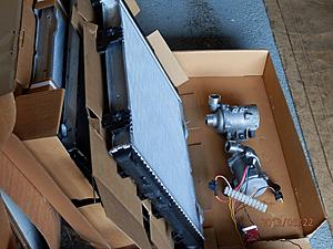
Here's a close-up of the pump controller - its only about two inches across. This is the first pump controller with customized firmware for charge cooling systems. The knob in the middle sets one of sixteen operating modes - essentially the target coolant temperature, plus a few test modes. There's a row of seven LEDs that can display either the coolant temp or the pump speed, depending on the advanced settings. In this picture its showing the ambient temp of my garage, which is about 20degC.

And here's the BMW radiator alongside the stock heat exchanger. All the radiators I short-listed for trial installation are about the same width as the stock HE, but about twice the thickness and twice the height. The old Bosch pump is sat alongside the Pierburg BMW pumps. The Tecomotive controller works with any Pierburg electric water pump - there are several variants. They're used on most current petrol engines, except the turbo-charged sixes and eights.
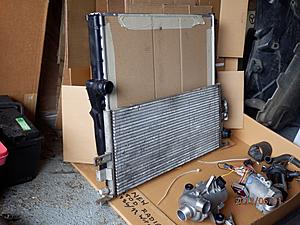
One of the advantages of the full-height HE is that all of the air going into the engine compartment has to go through the HE. In the stock configuration, the HE (and the ABC cooler) present the incoming air with a high-resistance, alternative flow paths to going through the condenser and the radiator alone. I had presumed that given the choice, the air will take the low-resistance path, and most of it will go round the HE instead. I think I got some proof of that - see what's behind the ABC cooler:
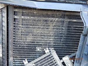
The condenser is quite choked up behind the cooler; its pretty obvious there's not much airflow there. Although the cooler is only 16mm thick, its still enough to persuade the air to go around it. I obviously cleaned it up with a vacuum and a brush.
This is one of the reasons why I've been keen to avoid the popular deep, shallow, coolers that many people use. These are typically around 200mm high and 50-75mm thick. I think that amounts to a lot of air resistance, and although the cores have large volume, I expect they won't get much air flowing through them. I think this picture is some proof of what had only been a conjecture till now
Obviously, I'm now working on getting all this gear fitted to my car.
Nick
Here are three engine radiators - two Mercedes and one BMW, plus two BMW engine coolant pumps and the Tecomotive electric pump controller.

Here's a close-up of the pump controller - its only about two inches across. This is the first pump controller with customized firmware for charge cooling systems. The knob in the middle sets one of sixteen operating modes - essentially the target coolant temperature, plus a few test modes. There's a row of seven LEDs that can display either the coolant temp or the pump speed, depending on the advanced settings. In this picture its showing the ambient temp of my garage, which is about 20degC.
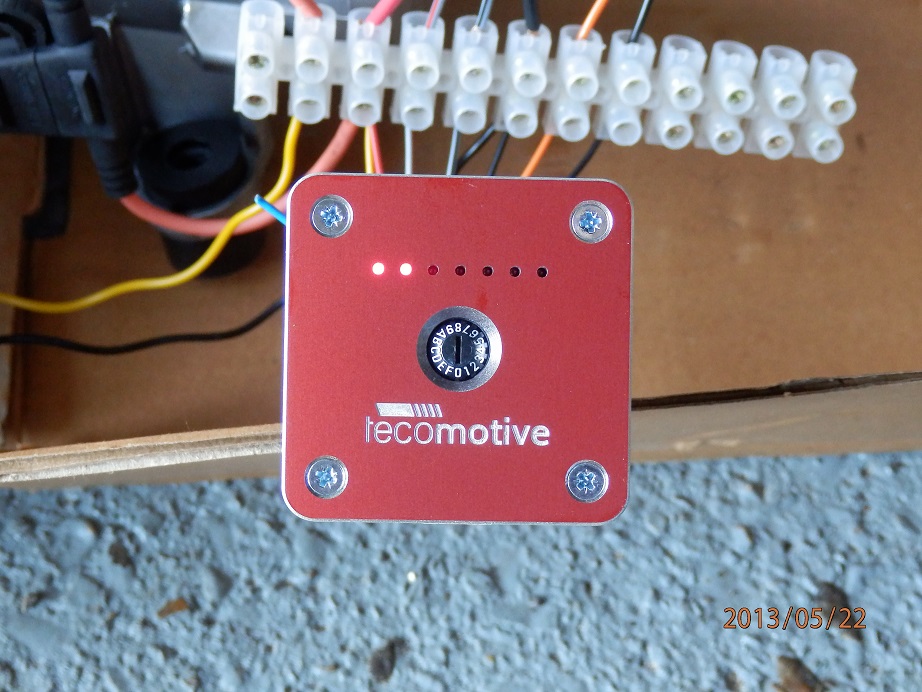
And here's the BMW radiator alongside the stock heat exchanger. All the radiators I short-listed for trial installation are about the same width as the stock HE, but about twice the thickness and twice the height. The old Bosch pump is sat alongside the Pierburg BMW pumps. The Tecomotive controller works with any Pierburg electric water pump - there are several variants. They're used on most current petrol engines, except the turbo-charged sixes and eights.

One of the advantages of the full-height HE is that all of the air going into the engine compartment has to go through the HE. In the stock configuration, the HE (and the ABC cooler) present the incoming air with a high-resistance, alternative flow paths to going through the condenser and the radiator alone. I had presumed that given the choice, the air will take the low-resistance path, and most of it will go round the HE instead. I think I got some proof of that - see what's behind the ABC cooler:
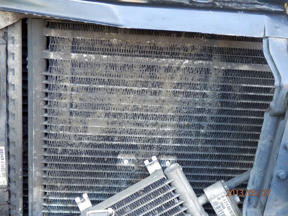
The condenser is quite choked up behind the cooler; its pretty obvious there's not much airflow there. Although the cooler is only 16mm thick, its still enough to persuade the air to go around it. I obviously cleaned it up with a vacuum and a brush.
This is one of the reasons why I've been keen to avoid the popular deep, shallow, coolers that many people use. These are typically around 200mm high and 50-75mm thick. I think that amounts to a lot of air resistance, and although the cores have large volume, I expect they won't get much air flowing through them. I think this picture is some proof of what had only been a conjecture till now
Obviously, I'm now working on getting all this gear fitted to my car.
Nick
Last edited by Welwynnick; Jun 10, 2013 at 03:52 PM.


