When you click on links to various merchants on this site and make a purchase, this can result in this site earning a commission. Affiliate programs and affiliations include, but are not limited to, the eBay Partner Network.
I would like to connect my CTEK to the under hood battery connections and have it be a permanent connection to the CTEK extension. The problem is that the positive �blade� connector doesn�t allow for a convenient connection point allowing for the hood to be closed. Has anyone found a connector that might work? I realize that I could do this directly to the battery in the trunk but I�d rather use the hood location if possible.
I�ve toyed with the idea of drilling the blade connector so I could bolt in an eyelet connector, but that would require a small angle drill that I don�t have in my tool chest. Maybe my dentist does. Any thoughts would be appreciated.
All Cars Lost To Hurricane Isaac (W124 E420 revived - added 88 Allante 14 S550, 17 S63
If you remove the ornamental paneling, there is a junction box (Prefuse box) with many live positive connections, including the positive jumper spade. They all have relatively small 3-6mm stud and nuts. You can connect it there as the M1 stud interface connects to the starter - same destination as the positive jumper spade
I can get you the wiring diagram if you don't have access, but stud posts M1, M2, MR3 all come directly from the battery (G1), and the spade ties into that circuit, but you do have choices in there as all are live just as the spade jumper post.
for a visual, search P/N A2225402350 (or without the "A"), it should show a pic of the prefuse module (F32)
***WARNING*** high amperage live circuits, disconnect the ground before any tinkering, and of course do this at your own risk...
what's a CTEK?
Originally Posted by Barry Hanna
I would like to connect my CTEK to the under hood battery connections and have it be a permanent connection to the CTEK extension. The problem is that the positive “blade” connector doesn’t allow for a convenient connection point allowing for the hood to be closed. Has anyone found a connector that might work? I realize that I could do this directly to the battery in the trunk but I’d rather use the hood location if possible.
I’ve toyed with the idea of drilling the blade connector so I could bolt in an eyelet connector, but that would require a small angle drill that I don’t have in my tool chest. Maybe my dentist does. Any thoughts would be appreciated.
All Cars Lost To Hurricane Isaac (W124 E420 revived - added 88 Allante 14 S550, 17 S63
Originally Posted by Barry Hanna
Thanks for the reply. A CTEK Is a maintenance battery charger. Like a Battery Tender.
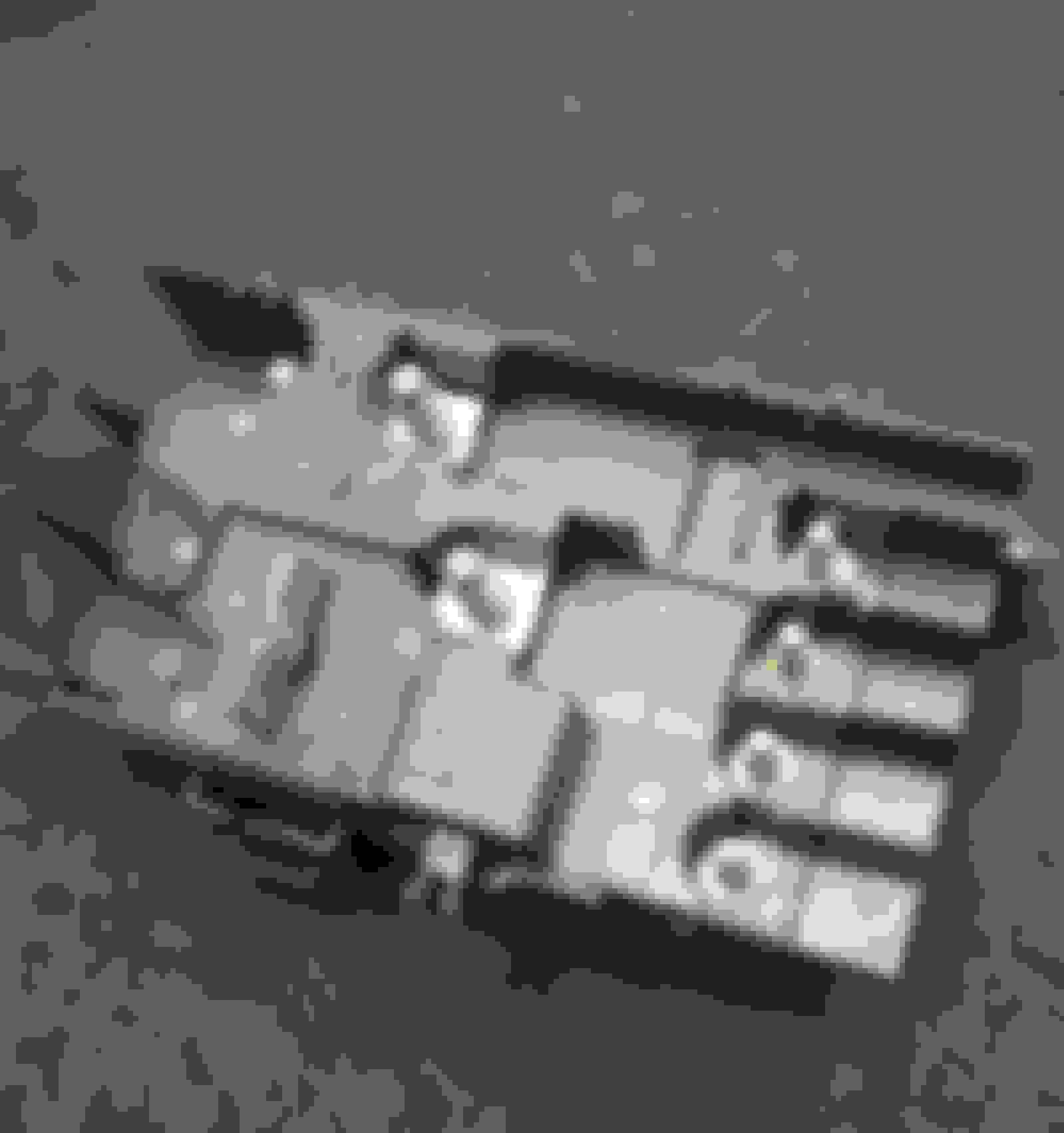
Hi just to close this out, here is a pic of the prefuse box showing the studs, all of these will charge the battery. A ring terminal for the CTEK and nut can be connected here.. The positive jumper spade is visible also.
It is a Great idea you have.
Prefuse box, connections removed, the terminal annotations shown Mx, etc.
Lou your CTEC toy will have a jumper that connects to a positive post and to ground. Be sure it is fused. The fuse is usually built into the leads you connect to the car.
I have been thinking of doing the same on my S550. I used a CTEK for years on my SL500. On the SL I did it in the trunk and the car did not mind having the trunk slightly open for the power cord. Just got the S550 so I will do the same for it under hood as the trunk would probably not be happy left open slightly due to power closure.
Thanks for power block info.
Originally Posted by kafklatsch
Hi just to close this out, here is a pic of the prefuse box showing the studs, all of these will charge the battery. A ring terminal for the CTEK and nut can be connected here.. The positive jumper spade is visible also.
It is a Great idea you have.
Prefuse box, connections removed, the terminal annotations shown Mx, etc.
***WARNING*** high amperage live circuits, disconnect the ground before any tinkering, and of course do this at your own risk..
Does this mean that I should disconnect the negative terminal on the main battery before doing this? If so, I’d rather do the “trunk diving” to access the battery than deal with electrical gremlins later, but ‘geeseh!
All Cars Lost To Hurricane Isaac (W124 E420 revived - added 88 Allante 14 S550, 17 S63
There is always a chance of contacting an exposed point on the negative ground of the car body and cause arcing.
Even the hole through the blade could allow a short to ground during the process
Personally i'd do "without" disconnecting the battery by placing a heavy blanket around the area im working to eliminate the possible short. I've done that a dozen or more times in my DIY life.. a thick plastic sheet/tarp will work also
But as a forum, we have to place cautionary notes if the possibility looms
Originally Posted by Barry Hanna
***WARNING*** high amperage live circuits, disconnect the ground before any tinkering, and of course do this at your own risk..
Does this mean that I should disconnect the negative terminal on the main battery before doing this? If so, I�d rather do the �trunk diving� to access the battery than deal with electrical gremlins later, but �geeseh!
All Cars Lost To Hurricane Isaac (W124 E420 revived - added 88 Allante 14 S550, 17 S63
I like your idea, and if you notice the engine seal strip..., it goes inside the jumper and panel. So the charger cord could route through at the windshield... I am now considering doing this with my "battery tender" brand.... no fancy CTEL for me...
Originally Posted by Barry Hanna
***WARNING*** high amperage live circuits, disconnect the ground before any tinkering, and of course do this at your own risk..
Does this mean that I should disconnect the negative terminal on the main battery before doing this? If so, I�d rather do the �trunk diving� to access the battery than deal with electrical gremlins later, but �geeseh!
Exactly, it looks like connecting to M1 (if it’s threaded) with my ring terminal should be a pretty straightforward install and the connection cord would have an easy exit to wherever the routing is preferred. And, yes, all of the extension leads I’ve seen are fused.
All Cars Lost To Hurricane Isaac (W124 E420 revived - added 88 Allante 14 S550, 17 S63
Yes
That is acceptable for a down and dirty charge...it's what I do now,
but i like the idea by the original poster... i likely will switch over to his suggestion
btw... that compartment is pristine...my own is a 10.... you're somewhere above that... nice
Cheers
Originally Posted by waterzap99
For mine, I wound a think piece of copper wire around the ground to clip onto something. Then rubber block to hold up the hood. No issues
If you remove the ornamental paneling, there is a junction box (Prefuse box) with many live positive connections, including the positive jumper spade. They all have relatively small 3-6mm stud and nuts. You can connect it there as the M1 stud interface connects to the starter - same destination as the positive jumper spade
I can get you the wiring diagram if you don't have access, but stud posts M1, M2, MR3 all come directly from the battery (G1), and the spade ties into that circuit, but you do have choices in there as all are live just as the spade jumper post.
for a visual, search P/N A2225402350 (or without the "A"), it should show a pic of the prefuse module (F32)
***WARNING*** high amperage live circuits, disconnect the ground before any tinkering, and of course do this at your own risk...
what's a CTEK?
Thank you for the info on the prefuse box. I am in the process of hardwiring a CTEK charging cable. The B1 terminal is the most convenient one for my wire routing notion. Just checking that it is direct to main battery. You mentioned M1, M2 and MR3. How about B1?
I will be clamping the negative CTEK lead to the negative charging post. I'll post photos here when complete.
Prefuse box before addition of positive charger cable:
prefuse box after addition of positive lead
Negative lead connection. Tinned wire clamped on
CTEK input connector. One has to open the hood for connection. I left enough cable to route it elsewhere if I chose to in the future
Do you know if this connection also charges the auxiliary battery in the trunk? I�m looking to do this to my S550 cabriolet. Also for the ground connection did you just unscrew the ground post and install with a ring connector? Thank for any help great DIY project
Thank you for the info on the prefuse box. I am in the process of hardwiring a CTEK charging cable. The B1 terminal is the most convenient one for my wire routing notion. Just checking that it is direct to main battery. You mentioned M1, M2 and MR3. How about B1?
I will be clamping the negative CTEK lead to the negative charging post. I'll post photos here when complete.
Thanks.
Originally Posted by Dave3359
Do you know if this connection also charges the auxiliary battery in the trunk? I�m looking to do this to my S550 cabriolet. Also for the ground connection did you just unscrew the ground post and install with a ring connector? Thank for any help great DIY project
I do not know the conditions that connect the aux battery to the charging system. I am pretty sure it is not connected when the car is not running. I am new to this machine, maybe a more experienced one can chime in. The negative lead is tinned with solder and firmly clamped to the ground stud..
I do not know the conditions that connect the aux battery to the charging system. I am pretty sure it is not connected when the car is not running. I am new to this machine, maybe a more experienced one can chime in. The negative lead is tinned with solder and firmly clamped to the ground stud..
So I just wired my CTEK in i think I took me longer to remove the top cover than the wiring part. I�m still hoping someone will jump in about it charging the auxiliary battery?
Mercedes SLR McLaren 722 S Is Extremely Rare Example Modified by McLaren
Slideshow: A one-of-one U.S.-spec Mercedes-Benz SLR McLaren Roadster became even rarer after a factory-backed transformation at McLaren's headquarters.