When you click on links to various merchants on this site and make a purchase, this can result in this site earning a commission. Affiliate programs and affiliations include, but are not limited to, the eBay Partner Network.
CDK, from a previous thread, we have explored possible ways to avoid burning the ECM since at this time we have no idea the root cause. Since I heard episodes of burning cars and even homes, I have been real concerned since my SL500 sleeps by the side of a big lawn mower with two plastic tanks of fuel 5 gallons each. If the car catches fire and reaches the lawn mower, my home will be in flames.
So, for my piece of mind I am implementing a fail-safe system that will disconnect the rear battery ground and will trigger an audible alarm. I am gathering the parts and soon I will not be thinking of fires...!
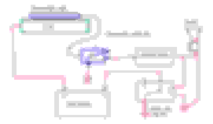
The system works as follows: A thermostatic switch (capillary type) is placed over the BCM and set to trigger to 160 F. While the temp is not reached, the thermostat switch will remain open. The heavy-duty relay will keep the battery connected to ground. If for any reason the BCM gets hot, the thermostatic valve will connect the + lead to a set of latching relays. These relays will stay on and will activate the heavy-duty NC relay to open the circuit and the rear battery gets disconnected. At the same time an audible alarm is activate. If nobody is around the battery will keep the alarm going till the battery dies!
Let me have your feedback!
These relays will stay on and will activate the heavy-duty NC relay to open the circuit and the rear battery gets disconnected. At the same time an audible alarm is activate. If nobody is around the battery will keep the alarm going till the battery dies!
Let me have your feedback!
From your drawing, you will need to re-think the connections.
Your circuit will isolate the -ve battery terminal, so when the heavy duty relay is activated, the battery is disconnected, so what will keep the relay energised, and sounder sounding?
As soon as the relay energizes it will cut the battery, and so de-energize, putting battery back in circuit, which would then re-energizing the relay. The relay will rapidly go ON-OFF-ON-OFF........
To solve, the heavy duty relay, and sounder, need connecting directly to battery -Ve terminal.
The latching relays are not necessary, as the heavy duty relay could be configured to be self latching by connecting the normally open contact to the relay coil, holding it on (An NC switch can then be used to easily reset the relay, look up DOL starter on google..)
You would also need to totally eliminate any way of a false trigger especially while driving.160degF (70degC) is close to normal operating temperature of power electronics.
What are you going to do about the front starter battery? Its connected to the BCM also!
I would also not recommend using a mechanical relay switching in this way, as the only time it will energize is in an emergency condition, so may not operate for years (hopefully). You then couldn't guarantee it would operate, as the contacts could weld (due to permanently carrying high current), or mechanical failure due to vibration. This switching system would fail industry safety standards (in the UK and EU at least). I am not saying it wouldn't work, but it has its potential issues.
gOrsq, thank you for your feedback.
Let me address your concerns.
1.-The relays will be connected to the battery negative before the disconnecting relay, which is at the end of the (-) cable, then to ground.
2.-The function of the latching relays is to keep the + pulse continuous when the temporary pulse of the thermal switch re-opens. The (-) is connected to the (-) battery pole.
3.-The heavy duty NC relay is connected between the ground and the battery (-) pole.
4.-I placed a thermocouple over the BCM to see how hot it gets and under a 110F outside temp, and didn't go over 120F. The thermal switch is adjustable and could increase the triggering temperature.
5.-You got a point with the front starter battery....! will it cause the BCM to fry? Do not know, but a parallel heavy duty relay could be use on its connection with the BCM, them as the BCM temp triggers, front (+) and Rear (-) will be disconnected!
6.-You may be right on the possibility of these heavy duty relays rated at 300 amps to stick due to continuous duty. They should be connected unless the BCM temperature triggers by the capillary tube/switch combination!
I wonder if anyone has the BCM electrical schematic so I can see how the interaction of the system is electronically manage.! I one of you have if, please share!
Last edited by elMacko; 09-06-2023 at 03:30 PM.
Reason: Adding text
1.-The relays will be connected to the battery negative before the disconnecting relay, which is at the end of the (-) cable, then to ground.
No problem, your original drawing was unclear regarding this.
2.-The function of the latching relays is to keep the + pulse continuous when the temporary pulse of the thermal switch re-opens. The (-) is connected to the (-) battery pole.
Yes I understand their function, but if you wire the NO contact of the main relay back to the coil +ve you will make a self latching relay (untill the battery volts die). Just saving complexity and component count
3.-The heavy duty NC relay is connected between the ground and the battery (-) pole.
4.-I placed a thermocouple over the BCM to see how hot it gets and under a 110F outside temp, and didn't go over 120F. The thermal switch is adjustable and could increase the triggering temperature.
5.-You got a point with the front starter battery....! will it cause the BCM to fry? Do not know, but a parallel heavy duty relay could be use on its connection with the BCM, them as the BCM temp triggers, front (+) and Rear (-) will be disconnected!
All OK.
6.-You may be right on the possibility of these heavy duty relays rated at 300 amps to stick due to continuous duty. They should be connected unless the BCM temperature triggers by the capillary tube/switch combination!
I wonder if anyone has the BCM electrical schematic so I can see how the interaction of the system is electronically manage.! I one of you have if, please share!
Saw a burnt BCM for sale. Seller wanted �500!
There are a few other issues to consider, but basically you have a good idea, so long as the heavy duty relay will actually energize when required, so don't I want to sound too negative.
My qualification is I am an electro-mechanical engineer, working on systems from 20mA instrumentation and PC based control systems to 200kW motors driving 4000 tonne Hydraulic presses, including all the switch gear and control systems.
gOrsq, great you found no issues with the proposed system. As you pointed out, these BCM's are almost extinct and the holders know it, so they want an arm and a leg for it...! My idea of cutting the power before the BCM completely burns is to have the option of preserving the integrity of the unit for having someone who could rebuild it!
My components cost under $50, which is well worth the investment!
I have been reading all the related post and a while back CaliBenzDriver posted what he thinks is the root cause of failure, attributing it to voltage spikes that occur in Miliseconds on the relays coils.
I am a Mechanical engineer with great experience in automotive systems mainly in the mechanical side. I have ventured in electromechanics and electronics, but not to the "high school" level.!
Attached is the "spikes" explanation
when I first bough tour r230 2006 the red battery light was on all the time unless I turned it off from the steering wheel. The previous owner said it happened after he jump started it. Probably incorrectly. I was able to scan for BNC codes and it had 1 code set. I cleared it and the red message has never come back. (touch wood). You'll need to scan it with a reader that is compatible with the BCM.. I use an icarsoft unit.
Wow this is a great thread, fantastic Electronic diagnostic work with data and bench design solutions, with Mathematical theory and Cost estimates. I am very impressed as well as happy to have avoided Red battery lights so far.
keep up the great work on this and thank you for sharing your knowledge and excellent posts.
Tom, I have just encountered a similar problem with my 2008 SL 55. Rear battery not charging when car is running but front is charging. Like you said the front battery does not always show its charging when running but when it does it�s around 14.2 volts. I have checked the fuses in the passenger footwell and they are good. Do you suspect the rear battery is bad? Even if it�s bad shouldn�t my meter read alternator output at the battery?
Tom, I have just encountered a similar problem with my 2008 SL 55. Rear battery not charging when car is running but front is charging. Like you said the front battery does not always show its charging when running but when it does it�s around 14.2 volts. I have checked the fuses in the passenger footwell and they are good. Do you suspect the rear battery is bad? Even if it�s bad shouldn�t my meter read alternator output at the battery?
There are at least two Toms on this thread...how old is the rear battery, sometimes a "well depleted" battery needs a higher amp "shock" (outside the car) to get it to start charging. It's a cheap fix (relatively) to follow the manual carefully and replace the rear battery with a new one to diagnose/isolate.
The problem is that when running voltmeter shows no charge going to rear battery.
You are right, that is a problem and I do not know if it is BCM or not. My independent did my BCM work so I I have not got any experience first hand, sorry
Did you pull the fuses to check them or leave them in place and check voltage on either side? I believe yiu need to pull them because they will read voltage on both sides if they are bad.
Tom, I have just encountered a similar problem with my 2008 SL 55. Rear battery not charging when car is running but front is charging. Like you said the front battery does not always show its charging when running but when it does it’s around 14.2 volts. I have checked the fuses in the passenger footwell and they are good. Do you suspect the rear battery is bad? Even if it’s bad shouldn’t my meter read alternator output at the battery?
If the front battery is charging, then the alternator and both pre-fuses in F52 must be OK.
The rear battery is connected directly to the alternator so it should be charging too, so it is likely that the rear battery is cactus and is not accepting charge. Then you should have had, or may have had the red battery light.
As previously mentioned, disconnect it and charge it up fully then measure the charging voltage again. If you're getting the 'convenience functions unavailable' message after a day or two that indicates a weak rear battery. Many here swear by original MB batteries.
Last edited by Tom Manning; 03-03-2024 at 05:42 PM.
You are right, that is a problem and I do not know if it is BCM or not. My independent did my BCM work so I I have not got any experience first hand, sorry
The BCM has absolutely nothing to do with the rear battery charging. Rear battery charges as with a conventional system.
So either pre-fuse is blown, Alternator is bad, battery is bad, or there is a wiring fault.
Probably just the regulator. There was a recall on early cars. You can buy the regulator separately, but I think the update has regulation done in the main ECU, not in the alternator as in early cars. Check your year.
 09-05-2023, 01:20 PM